EP0832495B1 - Dispositif de reglage de positionnement d'un siege motorise - Google Patents
Dispositif de reglage de positionnement d'un siege motorise Download PDFInfo
- Publication number
- EP0832495B1 EP0832495B1 EP96922105A EP96922105A EP0832495B1 EP 0832495 B1 EP0832495 B1 EP 0832495B1 EP 96922105 A EP96922105 A EP 96922105A EP 96922105 A EP96922105 A EP 96922105A EP 0832495 B1 EP0832495 B1 EP 0832495B1
- Authority
- EP
- European Patent Office
- Prior art keywords
- yoke
- microswitches
- actuating
- housing
- leaf spring
- Prior art date
- Legal status (The legal status is an assumption and is not a legal conclusion. Google has not performed a legal analysis and makes no representation as to the accuracy of the status listed.)
- Expired - Lifetime
Links
- 230000001413 cellular effect Effects 0.000 claims description 6
- 229920001296 polysiloxane Polymers 0.000 claims description 2
- 239000012528 membrane Substances 0.000 claims 2
- 238000006243 chemical reaction Methods 0.000 claims 1
- 210000002445 nipple Anatomy 0.000 description 5
- OKTJSMMVPCPJKN-UHFFFAOYSA-N Carbon Chemical compound [C] OKTJSMMVPCPJKN-UHFFFAOYSA-N 0.000 description 1
- 229910000831 Steel Inorganic materials 0.000 description 1
- 230000006978 adaptation Effects 0.000 description 1
- 238000005452 bending Methods 0.000 description 1
- 229910052799 carbon Inorganic materials 0.000 description 1
- 229910003460 diamond Inorganic materials 0.000 description 1
- 239000010432 diamond Substances 0.000 description 1
- 238000006073 displacement reaction Methods 0.000 description 1
- 238000005530 etching Methods 0.000 description 1
- 230000010354 integration Effects 0.000 description 1
- 239000000463 material Substances 0.000 description 1
- 239000002184 metal Substances 0.000 description 1
- 238000000465 moulding Methods 0.000 description 1
- 210000000056 organ Anatomy 0.000 description 1
- 239000010959 steel Substances 0.000 description 1
- 238000004381 surface treatment Methods 0.000 description 1
Images




Classifications
-
- H—ELECTRICITY
- H01—ELECTRIC ELEMENTS
- H01H—ELECTRIC SWITCHES; RELAYS; SELECTORS; EMERGENCY PROTECTIVE DEVICES
- H01H25/00—Switches with compound movement of handle or other operating part
-
- B—PERFORMING OPERATIONS; TRANSPORTING
- B60—VEHICLES IN GENERAL
- B60N—SEATS SPECIALLY ADAPTED FOR VEHICLES; VEHICLE PASSENGER ACCOMMODATION NOT OTHERWISE PROVIDED FOR
- B60N2/00—Seats specially adapted for vehicles; Arrangement or mounting of seats in vehicles
- B60N2/02—Seats specially adapted for vehicles; Arrangement or mounting of seats in vehicles the seat or part thereof being movable, e.g. adjustable
- B60N2/0224—Non-manual adjustments, e.g. with electrical operation
- B60N2/0226—User interfaces specially adapted for seat adjustment
- B60N2/0228—Hand-activated mechanical switches
-
- B—PERFORMING OPERATIONS; TRANSPORTING
- B60—VEHICLES IN GENERAL
- B60N—SEATS SPECIALLY ADAPTED FOR VEHICLES; VEHICLE PASSENGER ACCOMMODATION NOT OTHERWISE PROVIDED FOR
- B60N2/00—Seats specially adapted for vehicles; Arrangement or mounting of seats in vehicles
- B60N2/02—Seats specially adapted for vehicles; Arrangement or mounting of seats in vehicles the seat or part thereof being movable, e.g. adjustable
- B60N2/0224—Non-manual adjustments, e.g. with electrical operation
- B60N2/0226—User interfaces specially adapted for seat adjustment
- B60N2/0235—Joysticks
Definitions
- the present invention relates to a device for adjusting positioning of motorized seats, in particular vehicle seats automobiles.
- the front seats of a motor vehicle are adjustable in several directions. By vehicle seat, we must understand as well the seat or seat proper on which the driver or operator sits passenger than the record.
- the object of the present invention is to propose a device for adjustable seat positioning that is flexible depending on the use to be made of it by the car manufacturer.
- the present invention relates to a device for adjusting positioning of a seat, of the type in which switches are mounted, at the at least one actuator of said switch and at least one touch of control of the actuating member, characterized in that it comprises in addition to a honeycomb housing in which is housed at least one of the breakers and in that the actuating member is constituted by a portable device provided with minus an actuation ramp.
- An advantage of the present invention lies in the fact that the breakers used are independent of each other thanks to the fact that they are mounted in a honeycomb case. In addition, it is possible to inhibit one or several seat positions, for example double switching in vertical.
- the device shown in Figure 1 is intended for adjusting position of the seat and back of a seat of a motor vehicle, the seat position control being independent of that relating to the folder; therefore, separate position commands could be provided if it turns out to be necessary.
- the device comprises a lower cover 1 and a plastron upper 2 forming a cover for the cover and on which a control button 3 for adjusting the seat cushion position and a control button 4 for adjusting the seat back position.
- the control keys 3 and 4 are shown in top view and in view of below in the center and on the right side of the board of figure 1 respectively.
- the control assembly for adjusting the position of the seat comprises a honeycomb case 6 comprising as many cells 7 as there are switches, for example six in number and referenced 8 1 to 8 6 , necessary for positioning said seat, not shown, said switches 8 1 to 8 6 being mounted on a printed circuit 9 and each comprising a movable contact of the piston type, the contacts being referenced 10 1 to 10 6 .
- the honeycomb housing 6 is mounted from above so as to allow the breakers 8 to be housed in the corresponding cells, elastic tabs 11 being inserted in holes 12 of which only one is visible in Figure 1, and formed in the printed circuit 9, to ensure the connection between said cellular housing 6 and printed circuit 9.
- the cellular housing 6 comprises, at its center, a stud 18 whose function will be described later.
- the actuator blade 13 In a metal plate called the actuator blade 13 are cut and folded partly upwards of the flexible arms 14, the horizontal parts 15 of which are in constant abutment on the contacts 10 1 to 10 6 of the breakers 8, so as to allow cooperation with said contacts.
- the flexible arms 14, by their deformation, take up any play between said actuating blade 13 and said contacts 10 1 to 10 6 and also make it possible to transform the transverse forces of the actuating blade 13 into vertical forces on the contacts 10 1 to 10 6 of the switches 8, in order not to damage the switching module.
- a player 16 constituting an actuating member is mounted above the actuating blade 13 and comprises on the underside actuating ramps 17 cooperating with the flexible arms 14 (FIGS. 2 and 3).
- Each ramp 17 preferably comprises a part of the type hemispherical in contact with the corresponding arm 14 of the blade actuation 13, said arm 14 having an inclination which depends on the characteristics of the maneuvering and actuating strokes as well that possibly efforts to transmit.
- the inclination of the arm 14 is between 20 and 45 °.
- the player 16 includes an operating member or rod 19 which is housed in a space 20 provided for this purpose in the control button 3, as well as mechanical stops 21 formed at the four corners of the base 22 of the player 16.
- a recess 17b for example in the form of a diamond, is formed on the internal face of the base 22 and receives the stud 18 of the honeycomb housing 6. The dimensions of the recess 17b can be chosen so that a direction of movement of the player is inhibited . If you do not want to allow the seat to go up or down, we will choose, in the case of the diamond-shaped recess, a length S of the small diagonal such that S / 2 is less than the switching stroke of the player 16.
- Flexible arms 26 are produced in the blade 23 by cut-out and slight upward folding.
- a passage 27 is formed in the blade 23 for the passage of the operating rod 19 of the portable player 16.
- a cover 28 provided with a passage 29 for the rod 19 has ramps 30 on the internal faces 28a of the four lateral sides 31 of the cover, two of the four ramps 30 being shown in FIG. 1. The ramps 30 cooperate by sliding with the flexible arms 24 of the return blade 23 to bring back the mobile assembly in the initial position, while the flexible arms 26 are intended to compensate for the mechanical play between the player 16 and the cover 28.
- the shape, for example in H, and the dimensions of passage 29 are chosen so that the player 16 can move in the directions A to D of the control button 3.
- the internal walls 28a of the lateral sides 31 constitute stops mechanical for the stops 21 of the portable player 16.
- An important feature of the present invention lies in the fact that whatever the force exerted on the control button 3, the force transmitted vertically on each of the contacts 10 1 to 10 6 remains intact and equal to a predetermined value, for example of the order of 6N. Indeed, thanks to the mechanical stop of the player 16 on the internal walls 28a of the cover 28, only part of the force exerted on the control button is transmitted by the player 16 to the flexible arms 14 of the actuating blade 13
- the dimensioning of said flexible arms as well as its mechanical properties such as bending, modulus and other moment of inertia are chosen so that for a force F exerted vertically at the end of a flexible arm 14, the total force exerted on each of the breakers remains constant by application of the laws and formulas of resistance of the materials, not described because well known to specialists in the field.
- a movable assembly for controlling the position adjustment of a seat back is also provided in the device according to the invention but it is limited to a two-axis module because, in the majority of cases, it is necessary to tilt the backrest back or bring it forward.
- the assembly includes a honeycomb case 35 comprising two cells 36 for housing two breakers 37 identical to the breakers 8 and mounted on the printed circuit 9.
- the actuating member is constituted not by the player described above but by an actuator 38 comprising a vertical rod 39 and a base 40 in which are formed an oblong hole 41 and a cam 42, the lower part 43 of the rod vertical 39 being housed in a housing 44 formed in the housing alveolar 35.
- a lifting beam 45 is also mounted in the housing 35, as this is shown in Figures 4 and 4a and has the same function as the actuator blade 13 previously described.
- the lifter 45 includes a ball joint 46 which is disposed in the oblong orifice 41 of the actuator 38 and two pairs of arms 47 and 48, the two arms 47a and 47b or 48a and 48b of each pair being separated by a slot 49.
- the arms 47a and 48a are capable of approach the respective arms 47b and 48b depending on the position of the spreader 45, as shown in FIGS. 4 and 4a in which the spreader tilted around a pivot axis 70 to activate the piston 37a of the switch 37 on the right ( Figure 4) or it is in the rest position ( Figure 4a), none of the switches 37 being actuated in this position.
- a return blade 50 of the actuator 38 of shape corresponding to cam 42 is housed therein and it is mounted fixed in the cover 51 which is provided with a passage 52 for the rod 39 and which fits on the housing 35 to protect the various parts of the mobile assembly.
- the rod 39 is received and blocked by means suitable in a housing 53 of the control button 4.
- the front plate 2 forming a cover for the device according to the invention is provided with two suitable orifices 54 and 55 for the passage rods 19 and 39 respectively.
- the faceplate 2 may also include nipples 56, 57 or orifices such as for example orifice 58, cooperating with holes or pins provided in control button 3, like the nipple 59 which is housed in the orifice 58 while the nipple 57 is housed in recess 60. Obviously, we can reverse these organs and provide pins on the control button 3 and holes on the faceplate 2.
- FIGs 5 to 5b there is shown schematically three of the possible seat movements.
- pressure is exerted on one end of the control button 3, in the direction of the arrow A ', the pivot center being located on the axis P and approximately near the point P 1 .
- the switch 10 1 is switched. Thanks to the mechanical stop produced by the contact of the corresponding stop 21 on the internal wall 28a opposite the cover 28, no opposing torque is created at the other end of said control button 3 and it is thus ensured that the switch 10 6 is not switched.
- the rear ascent (FIG. 5a) of the seat is carried out by pressing on the other end of the control button 3 along the arrow B ′, the pivot center being approximately around the point P 2 on the axis P.
- Efforts exerted according to arrows A and B produce reverse movements, that is to say an ascent from the front of the seat or a descent from the rear of the seat, the switched breakers then being 8 3 or 8 4 .
- a raising or lowering of the seat, parallel to the floor or to any anterior position is ensured by the displacement of the control button 3 in the direction of the double arrow C, a direction being reserved for the rise, for example by switching the switches 8 3 and 8 4 , the other being reserved for the descent by switching of the switches 8 1 and 8 6 .
- the switches remain switched until the desired height positioning. In any position of the seat, it is possible, as described above, to correctly position the front and / or rear of the seat.
- nipple 59 on the command 3 prohibits or authorizes certain seat positions. Therefore the stud 59 disposed in the orifice 58 prohibits the movements of the button command 3 following the arrows A and A 'and the double arrows C and D then that the movements according to arrows B and B 'are authorized.
- the position of the seat backrest is adjusted by the control key 4 which pivots about a pivot axis, so to authorize the inclination of said file between two predetermined limits.
- This adjustment is carried out by switching one or other of the switches 37, the simultaneous switching of the two switches is not possible.
- the honeycomb housing 6 is replaced by another honeycomb housing 6 'in the cells of which the blisters 70 1 to 70 6 are arranged.
- an intermediate actuating member 71 is produced which comprises as many pairs of actuating pins as there are blisters.
- Each pair of pins comprises an upper pin 72 which cooperates with a flexible arm 14 of the actuator blade 13 and a lower pin 73 which cooperates with the associated blister.
- the blisters 70 1 to 70 8 are mounted on the conductive tracks of the printed circuit etching type.
- the blisters are interesting when you want to go from weak currents and they can be in the form of cups metallic, steel with or without surface treatment, or silicone with conductive pads, for example carbon.
Landscapes
- Engineering & Computer Science (AREA)
- Human Computer Interaction (AREA)
- Aviation & Aerospace Engineering (AREA)
- Transportation (AREA)
- Mechanical Engineering (AREA)
- Seats For Vehicles (AREA)
- Chairs For Special Purposes, Such As Reclining Chairs (AREA)
- Switches With Compound Operations (AREA)
Description
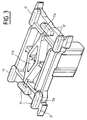
- la figure 1 est une vue éclatée du dispositif selon l'invention, avec certaines parties représentées également en vue de dessous et en perspective,
- la figure 2 est une coupe verticale du baladeur représenté,
- la figure 3 est une vue de dessous en perspective du baladeur de la figure 2,
- les figures 4 et 4a sont des vues en coupe du palonnier représenté sur la figure 1, dans une position de contact et au repos respectivement,
- les figures 5, 5a et 5b sont des représentations schématiques de divers mouvements autorisés dans un module 3 axes,
- la figure 6 est une vue de dessus d'un autre mode de réalisation de l'invention,
- la figure 7 est une vue en coupe selon VII-VII de la figure 6.
Longueur (L) = 10 mm ; largeur (l) = 2 mm ; épaisseur (e) = 0,25 mm ; flèche (f) = 1 mm ; module d'élasticité (Y) = 190 000 N/mm2 ; force (Ftk) à exercer sur un contact = 5N du rupteur considéré ; la force totale à l'extrémité du bras est TT = FR + F≈6N où FR est la force ramenée au bout du bras et F la force ayant produit la flèche f.
Claims (15)
- Dispositif de réglage de positionnement d'un siège du type comprenant un corps de boítier constitué par une partie formant couvercle (28, 51) et une partie de fond (1), un circuit imprimé (9) disposé dans ledit corps et sur lequel sont montés des rupteurs (8, 37), au moins un organe d'actionnement (16, 38) desdits rupteurs et au moins une touche (3, 4) de commande de l'organe d'actionnement, caractérisé en ce qu'il comprend en outre un boítier alvéolaire (6, 35) dans lequel est logé au moins un des rupteurs (8, 37) et en ce que l'organe d'actionnement est constitué par un baladeur (16, 38) muni d'au moins une rampe d'actionnement (17).
- Dispositif selon la revendication 1, caractérisé en ce que le baladeur (16) comprend autant de rampes (17) d'actionnement que de rupteurs (8) disposés dans le boítier alvéolaire (6) et en ce qu'une lame souple de rappel (23) est interposée entre le couvercle (28) et le baladeur (16), ladite lame souple (23) coopérant avec des rampes de positionnement (30) prévues dans ledit couvercle pour ramener le baladeur dans une position initiale de repos.
- Dispositif selon la revendication 2, caractérisé en ce que la lame souple (23) comprend, en partie supérieure, des pattes élastiques (26) pour compenser des jeux mécaniques entre le baladeur (16) et le couvercle 28).
- Dispositif selon la revendication 1 ou 2, caractérisé en ce qu'une lame (13) de transmission d'efforts est interposée entre le baladeur (16) et le boítier alvéolaire (6), ladite lame (13) comportant des bras souples inclinés (14) coopérant avec les rampes (17) du baladeur et les rupteurs (8), pour transformer les efforts transversaux du baladeur en efforts verticaux sur les rupteurs.
- Dispositif selon la revendication 4, caractérisé en ce que les rampes (17) présentent au moins une partie hémisphérique (17a).
- Dispositif selon la revendication 1, caractérisé en ce que le baladeur (16) est constitué par un actionneur (38) et un palonnier (45), ledit actionneur (38) étant pourvu, d'une part, d'un axe de transformation (39) de mouvements de la touche de commande (4) et, d'autre part, d'un orifice oblong (41) dans lequel est logé une rotule (46) du palonnier (45) qui comprend également un axe de pivotement (49) et deux leviers d'actionnement (47, 48).
- Dispositif selon la revendication 6, caractérisé en ce que le palonnier (45) comprend en outre des ailettes souples de rattrapage de jeu qui sont interposées entre un rupteur et les leviers d'actionnement.
- Dispositif selon la revendication 6, caractérisé en ce que l'actionneur comprend une came (42) de positionnement au repos et dans laquelle est logée une lame élastique de rappel (50).
- Dispositif selon l'une des revendications précédentes, caractérisé en ce qu'il comprend des moyens d'inhibition (18, 56, 57, 58) d'un ou plusieurs réglages de positionnement du siège.
- Dispositif selon la revendication 9, caractérisé en ce que les moyens d'inhibition sont constitués par un téton (18) monté sur le boítier (6) et qui se loge dans un évidement (17b) ménagé dans la face inférieure du baladeur (16).
- Dispositif selon la revendication 9, caractérisé en ce que les moyens d'inhibition sont constitués par un téton (59) prévu dans la touche de commande (3) et s'insérant dans un orifice (58) ménagé dans un plastron (2) formant couvercle général pour le dispositif.
- Dispositif selon l'une des revendications précédentes, caractérisé en ce que l'effort transmis verticalement à chacun des rupteurs (81 à 86) est constant et de valeur prédéterminée, d'environ 6N.
- Dispositif selon la revendication 1 ou 4, caractérisé en ce que le boítier alvéolaire (6') comprend un organe d'actionnement intermédiaire (71) comprenant des pions d'actionnement (72, 73) qui coopèrent avec les bras souples (14) de la lame d'actionnement (13) et les rupteurs.
- Dispositif selon la revendication 1 ou 13, caractérisé en ce que les rupteurs sont constitués par des cloquants (701 à 706) montés sur des pistes conductrices du circuit imprimé (9).
- Dispositif selon la revendication 14, caractérisé en ce que les cloquants (701 à 706) sont en silicone avec pastilles conductrices.
Applications Claiming Priority (3)
| Application Number | Priority Date | Filing Date | Title |
|---|---|---|---|
| FR9507074 | 1995-06-14 | ||
| FR9507074A FR2735610B1 (fr) | 1995-06-14 | 1995-06-14 | Dispositif de reglage de positionnement d'un siege motorise |
| PCT/FR1996/000892 WO1997000529A1 (fr) | 1995-06-14 | 1996-06-12 | Dispositif de reglage de positionnement d'un siege motorise |
Publications (2)
| Publication Number | Publication Date |
|---|---|
| EP0832495A1 EP0832495A1 (fr) | 1998-04-01 |
| EP0832495B1 true EP0832495B1 (fr) | 1999-01-20 |
Family
ID=9479979
Family Applications (1)
| Application Number | Title | Priority Date | Filing Date |
|---|---|---|---|
| EP96922105A Expired - Lifetime EP0832495B1 (fr) | 1995-06-14 | 1996-06-12 | Dispositif de reglage de positionnement d'un siege motorise |
Country Status (6)
| Country | Link |
|---|---|
| EP (1) | EP0832495B1 (fr) |
| JP (1) | JPH11507759A (fr) |
| DE (1) | DE69601427T2 (fr) |
| ES (1) | ES2129269T3 (fr) |
| FR (1) | FR2735610B1 (fr) |
| WO (1) | WO1997000529A1 (fr) |
Cited By (1)
| Publication number | Priority date | Publication date | Assignee | Title |
|---|---|---|---|---|
| DE10162764A1 (de) * | 2001-12-20 | 2003-07-03 | Valeo Schalter & Sensoren Gmbh | Schaltereinheit und Schalthebel mit Schaltereinheit |
Families Citing this family (4)
| Publication number | Priority date | Publication date | Assignee | Title |
|---|---|---|---|---|
| DE29823007U1 (de) | 1998-12-24 | 1999-04-01 | Abb Patent Gmbh, 68309 Mannheim | Schiebetaster |
| DE10002493C1 (de) * | 2000-01-21 | 2001-06-13 | Faure Bertrand Sitztech Gmbh | Kraftfahrzeugsitz-Verstellschalter |
| DE20300599U1 (de) | 2003-01-15 | 2003-03-20 | Metabowerke GmbH, 72622 Nürtingen | Elektrohandwerkzeuggerät mit Drehrichtungsumschaltung |
| FR2919751B1 (fr) | 2007-07-31 | 2012-03-16 | Sc2N Sa | Dispositif de commande electrique |
Family Cites Families (4)
| Publication number | Priority date | Publication date | Assignee | Title |
|---|---|---|---|---|
| FR2193241B1 (fr) * | 1972-07-21 | 1976-01-16 | Telemecanique Electrique | |
| DE3238048A1 (de) * | 1982-10-14 | 1984-04-19 | W. Gessmann GmbH, 7105 Leingarten | Verbundantrieb fuer schalt- oder stellglieder |
| DE3904771C1 (en) * | 1989-02-17 | 1990-06-07 | Leopold Kostal Gmbh & Co Kg, 5880 Luedenscheid, De | Switch arrangement for the actuators of vehicle seat parts |
| DE69211626T2 (de) * | 1991-07-31 | 1997-02-20 | Omron Tateisi Electronics Co | Schalteinrichtung |
-
1995
- 1995-06-14 FR FR9507074A patent/FR2735610B1/fr not_active Expired - Fee Related
-
1996
- 1996-06-12 EP EP96922105A patent/EP0832495B1/fr not_active Expired - Lifetime
- 1996-06-12 ES ES96922105T patent/ES2129269T3/es not_active Expired - Lifetime
- 1996-06-12 WO PCT/FR1996/000892 patent/WO1997000529A1/fr not_active Ceased
- 1996-06-12 JP JP9502709A patent/JPH11507759A/ja active Pending
- 1996-06-12 DE DE69601427T patent/DE69601427T2/de not_active Expired - Lifetime
Cited By (1)
| Publication number | Priority date | Publication date | Assignee | Title |
|---|---|---|---|---|
| DE10162764A1 (de) * | 2001-12-20 | 2003-07-03 | Valeo Schalter & Sensoren Gmbh | Schaltereinheit und Schalthebel mit Schaltereinheit |
Also Published As
| Publication number | Publication date |
|---|---|
| JPH11507759A (ja) | 1999-07-06 |
| WO1997000529A1 (fr) | 1997-01-03 |
| DE69601427D1 (de) | 1999-03-04 |
| DE69601427T2 (de) | 1999-08-19 |
| FR2735610A1 (fr) | 1996-12-20 |
| FR2735610B1 (fr) | 1997-08-22 |
| EP0832495A1 (fr) | 1998-04-01 |
| ES2129269T3 (es) | 1999-06-01 |
Similar Documents
| Publication | Publication Date | Title |
|---|---|---|
| FR2917230A1 (fr) | Dispositif pour la commande d'un appareil electronique | |
| EP2216201B1 (fr) | Unité de commande de siège électrique | |
| FR2677167A1 (fr) | Commutateur electrique, notamment pour la commande d'equipements et accessoires automobiles. | |
| EP2141718B1 (fr) | Dispositif de commande à molette semi-rotative | |
| WO2006010841A1 (fr) | Dispositif de commande a distance de gouvernes d'un aeronef | |
| WO1997000529A1 (fr) | Dispositif de reglage de positionnement d'un siege motorise | |
| FR2899719A1 (fr) | Commutateur electrique a voies de commutation multiples | |
| EP2412333B1 (fr) | Dispositif de commande sans fil pour commander un appareil chirurgical | |
| EP1197981B1 (fr) | Dispositif de commande d'un contacteur comprenant un transmetteur et transmetteur pour ce dispositif | |
| WO2006010842A1 (fr) | Dispositif de restitution artificielle d'effort antagoniste pour un dispositif de commande a distance de gouvernes d'un aeronef | |
| FR3089658A1 (fr) | Dispositif de commande d’un appareil électronique, procédés de réglage du dispositif et rétroviseur de véhicule automobile intégrant un tel dispositif. | |
| FR2737686A1 (fr) | Dispositif de commande pour siege de vehicule | |
| EP0844134B1 (fr) | Dispositif d'actionnement d'un organe de commande d'un mécanisme de siège de véhicule automobile et siège muni d'un tel dispositif | |
| FR2796201A1 (fr) | Commutateur a elements electriques de montage aise | |
| EP3602597B1 (fr) | Ensemble d'éléments de transmission de force pour commutateur | |
| EP1732096B1 (fr) | Dispositif de commande à levier basculant, de débattement angulaire réduit | |
| FR2733085A1 (fr) | Commutateur electrique comportant un organe commun d'actionnement de deux contacts electriques mobiles | |
| EP2020663A1 (fr) | Dispositif de commande électrique | |
| EP3975216A1 (fr) | Ensemble de pièces permettant la réalisation d'un interrupteur | |
| EP4297057A1 (fr) | Dispositif de commande à bascule à double actionnement dans un même sens avec retour haptique à double détente | |
| FR2932130A1 (fr) | Dispositif de commande pour la commande de reglage d'un siege de vehicule | |
| FR2680431A1 (fr) | Systeme de commande d'inversion d'un moteur electrique. | |
| EP4388569B1 (fr) | Dispositif de commande manuelle dont le rappel du bouton de commande se fait par un élément torique | |
| EP0384790B1 (fr) | Appareil interrupteur à commande électromagnétique ou forcée | |
| FR2792486A1 (fr) | Commutateur electrique multiple a tambour unique d'actionnement |
Legal Events
| Date | Code | Title | Description |
|---|---|---|---|
| PUAI | Public reference made under article 153(3) epc to a published international application that has entered the european phase |
Free format text: ORIGINAL CODE: 0009012 |
|
| 17P | Request for examination filed |
Effective date: 19971204 |
|
| AK | Designated contracting states |
Kind code of ref document: A1 Designated state(s): DE ES FR GB IT SE |
|
| GRAG | Despatch of communication of intention to grant |
Free format text: ORIGINAL CODE: EPIDOS AGRA |
|
| 17Q | First examination report despatched |
Effective date: 19980529 |
|
| GRAG | Despatch of communication of intention to grant |
Free format text: ORIGINAL CODE: EPIDOS AGRA |
|
| GRAH | Despatch of communication of intention to grant a patent |
Free format text: ORIGINAL CODE: EPIDOS IGRA |
|
| GRAH | Despatch of communication of intention to grant a patent |
Free format text: ORIGINAL CODE: EPIDOS IGRA |
|
| GRAA | (expected) grant |
Free format text: ORIGINAL CODE: 0009210 |
|
| AK | Designated contracting states |
Kind code of ref document: B1 Designated state(s): DE ES FR GB IT SE |
|
| REF | Corresponds to: |
Ref document number: 69601427 Country of ref document: DE Date of ref document: 19990304 |
|
| GBT | Gb: translation of ep patent filed (gb section 77(6)(a)/1977) |
Effective date: 19990311 |
|
| ITF | It: translation for a ep patent filed | ||
| PG25 | Lapsed in a contracting state [announced via postgrant information from national office to epo] |
Ref country code: DE Free format text: LAPSE BECAUSE OF FAILURE TO SUBMIT A TRANSLATION OF THE DESCRIPTION OR TO PAY THE FEE WITHIN THE PRESCRIBED TIME-LIMIT Effective date: 19990421 |
|
| REG | Reference to a national code |
Ref country code: ES Ref legal event code: FG2A Ref document number: 2129269 Country of ref document: ES Kind code of ref document: T3 |
|
| PGFP | Annual fee paid to national office [announced via postgrant information from national office to epo] |
Ref country code: ES Payment date: 19990611 Year of fee payment: 4 |
|
| PGFP | Annual fee paid to national office [announced via postgrant information from national office to epo] |
Ref country code: SE Payment date: 19990623 Year of fee payment: 4 |
|
| PLBE | No opposition filed within time limit |
Free format text: ORIGINAL CODE: 0009261 |
|
| STAA | Information on the status of an ep patent application or granted ep patent |
Free format text: STATUS: NO OPPOSITION FILED WITHIN TIME LIMIT |
|
| 26N | No opposition filed | ||
| PG25 | Lapsed in a contracting state [announced via postgrant information from national office to epo] |
Ref country code: GB Free format text: LAPSE BECAUSE OF NON-PAYMENT OF DUE FEES Effective date: 20000612 |
|
| PG25 | Lapsed in a contracting state [announced via postgrant information from national office to epo] |
Ref country code: SE Free format text: LAPSE BECAUSE OF NON-PAYMENT OF DUE FEES Effective date: 20000613 Ref country code: ES Free format text: THE PATENT HAS BEEN ANNULLED BY A DECISION OF A NATIONAL AUTHORITY Effective date: 20000613 |
|
| GBPC | Gb: european patent ceased through non-payment of renewal fee |
Effective date: 20000612 |
|
| EUG | Se: european patent has lapsed |
Ref document number: 96922105.0 |
|
| REG | Reference to a national code |
Ref country code: ES Ref legal event code: FD2A Effective date: 20020204 |
|
| REG | Reference to a national code |
Ref country code: FR Ref legal event code: PLFP Year of fee payment: 20 |
|
| PGFP | Annual fee paid to national office [announced via postgrant information from national office to epo] |
Ref country code: DE Payment date: 20150612 Year of fee payment: 20 |
|
| PGFP | Annual fee paid to national office [announced via postgrant information from national office to epo] |
Ref country code: IT Payment date: 20150612 Year of fee payment: 20 |
|
| PGFP | Annual fee paid to national office [announced via postgrant information from national office to epo] |
Ref country code: FR Payment date: 20150630 Year of fee payment: 20 |
|
| REG | Reference to a national code |
Ref country code: DE Ref legal event code: R071 Ref document number: 69601427 Country of ref document: DE |