EP0831757B1 - Joint prosthesis - Google Patents
Joint prosthesis Download PDFInfo
- Publication number
- EP0831757B1 EP0831757B1 EP96918708A EP96918708A EP0831757B1 EP 0831757 B1 EP0831757 B1 EP 0831757B1 EP 96918708 A EP96918708 A EP 96918708A EP 96918708 A EP96918708 A EP 96918708A EP 0831757 B1 EP0831757 B1 EP 0831757B1
- Authority
- EP
- European Patent Office
- Prior art keywords
- joint
- spacer part
- joint prosthesis
- polymer
- set forth
- Prior art date
- Legal status (The legal status is an assumption and is not a legal conclusion. Google has not performed a legal analysis and makes no representation as to the accuracy of the status listed.)
- Expired - Lifetime
Links
- 125000006850 spacer group Chemical group 0.000 claims abstract description 114
- 210000000988 bone and bone Anatomy 0.000 claims abstract description 57
- 210000001519 tissue Anatomy 0.000 claims abstract description 25
- 229920002988 biodegradable polymer Polymers 0.000 claims abstract description 15
- 239000004621 biodegradable polymer Substances 0.000 claims abstract description 15
- 229920001577 copolymer Polymers 0.000 claims abstract description 15
- 229920002959 polymer blend Polymers 0.000 claims abstract description 11
- 239000000463 material Substances 0.000 claims abstract description 8
- 239000002131 composite material Substances 0.000 claims abstract description 6
- 229920000642 polymer Polymers 0.000 claims description 17
- 239000000835 fiber Substances 0.000 claims description 15
- 239000000203 mixture Substances 0.000 claims description 10
- 239000004744 fabric Substances 0.000 claims description 9
- 238000010276 construction Methods 0.000 claims description 5
- 210000003041 ligament Anatomy 0.000 claims description 5
- 238000009954 braiding Methods 0.000 claims description 4
- 239000011248 coating agent Substances 0.000 claims description 2
- 238000000576 coating method Methods 0.000 claims description 2
- 150000001875 compounds Chemical class 0.000 claims 1
- 230000000593 degrading effect Effects 0.000 claims 1
- 238000009940 knitting Methods 0.000 description 13
- 238000004519 manufacturing process Methods 0.000 description 10
- 238000000034 method Methods 0.000 description 10
- 210000000281 joint capsule Anatomy 0.000 description 9
- 239000011148 porous material Substances 0.000 description 8
- 239000007943 implant Substances 0.000 description 7
- 238000005452 bending Methods 0.000 description 5
- 210000004439 collateral ligament Anatomy 0.000 description 5
- 238000005516 engineering process Methods 0.000 description 5
- 230000033001 locomotion Effects 0.000 description 5
- 239000011159 matrix material Substances 0.000 description 5
- 238000005259 measurement Methods 0.000 description 5
- 239000000126 substance Substances 0.000 description 5
- 238000005266 casting Methods 0.000 description 4
- 210000002683 foot Anatomy 0.000 description 4
- 239000002245 particle Substances 0.000 description 4
- 101710148592 PTS system fructose-like EIIA component Proteins 0.000 description 3
- 239000000654 additive Substances 0.000 description 3
- 238000006243 chemical reaction Methods 0.000 description 3
- 238000001125 extrusion Methods 0.000 description 3
- 210000003811 finger Anatomy 0.000 description 3
- 210000001037 metacarpus Anatomy 0.000 description 3
- 230000003387 muscular Effects 0.000 description 3
- 239000004033 plastic Substances 0.000 description 3
- 229920003023 plastic Polymers 0.000 description 3
- 239000000843 powder Substances 0.000 description 3
- 239000002994 raw material Substances 0.000 description 3
- 238000001356 surgical procedure Methods 0.000 description 3
- 230000008467 tissue growth Effects 0.000 description 3
- LCSKNASZPVZHEG-UHFFFAOYSA-N 3,6-dimethyl-1,4-dioxane-2,5-dione;1,4-dioxane-2,5-dione Chemical compound O=C1COC(=O)CO1.CC1OC(=O)C(C)OC1=O LCSKNASZPVZHEG-UHFFFAOYSA-N 0.000 description 2
- 239000004604 Blowing Agent Substances 0.000 description 2
- CURLTUGMZLYLDI-UHFFFAOYSA-N Carbon dioxide Chemical compound O=C=O CURLTUGMZLYLDI-UHFFFAOYSA-N 0.000 description 2
- 206010019909 Hernia Diseases 0.000 description 2
- 206010023204 Joint dislocation Diseases 0.000 description 2
- 238000003723 Smelting Methods 0.000 description 2
- 239000004902 Softening Agent Substances 0.000 description 2
- 241001062472 Stokellia anisodon Species 0.000 description 2
- 241001227561 Valgus Species 0.000 description 2
- 230000000996 additive effect Effects 0.000 description 2
- 239000012867 bioactive agent Substances 0.000 description 2
- 239000000919 ceramic Substances 0.000 description 2
- 239000003795 chemical substances by application Substances 0.000 description 2
- 230000001684 chronic effect Effects 0.000 description 2
- 238000003780 insertion Methods 0.000 description 2
- 230000037431 insertion Effects 0.000 description 2
- 210000003789 metatarsus Anatomy 0.000 description 2
- 229920001610 polycaprolactone Polymers 0.000 description 2
- 229920000728 polyester Polymers 0.000 description 2
- 230000003014 reinforcing effect Effects 0.000 description 2
- 238000011160 research Methods 0.000 description 2
- 238000009958 sewing Methods 0.000 description 2
- 229920000260 silastic Polymers 0.000 description 2
- 239000000243 solution Substances 0.000 description 2
- 238000009941 weaving Methods 0.000 description 2
- 210000000707 wrist Anatomy 0.000 description 2
- PAPBSGBWRJIAAV-UHFFFAOYSA-N ε-Caprolactone Chemical compound O=C1CCCCCO1 PAPBSGBWRJIAAV-UHFFFAOYSA-N 0.000 description 2
- 206010006585 Bunion Diseases 0.000 description 1
- IWDANOJGJIFBEL-UHFFFAOYSA-N C(C1)CC11CCCC1 Chemical compound C(C1)CC11CCCC1 IWDANOJGJIFBEL-UHFFFAOYSA-N 0.000 description 1
- OKTJSMMVPCPJKN-UHFFFAOYSA-N Carbon Chemical compound [C] OKTJSMMVPCPJKN-UHFFFAOYSA-N 0.000 description 1
- 102000008186 Collagen Human genes 0.000 description 1
- 108010035532 Collagen Proteins 0.000 description 1
- 239000004150 EU approved colour Substances 0.000 description 1
- 101000617478 Escherichia coli (strain K12) PTS system fructose-like EIIA component Proteins 0.000 description 1
- IAYPIBMASNFSPL-UHFFFAOYSA-N Ethylene oxide Chemical compound C1CO1 IAYPIBMASNFSPL-UHFFFAOYSA-N 0.000 description 1
- HTTJABKRGRZYRN-UHFFFAOYSA-N Heparin Chemical compound OC1C(NC(=O)C)C(O)OC(COS(O)(=O)=O)C1OC1C(OS(O)(=O)=O)C(O)C(OC2C(C(OS(O)(=O)=O)C(OC3C(C(O)C(O)C(O3)C(O)=O)OS(O)(=O)=O)C(CO)O2)NS(O)(=O)=O)C(C(O)=O)O1 HTTJABKRGRZYRN-UHFFFAOYSA-N 0.000 description 1
- 206010061218 Inflammation Diseases 0.000 description 1
- 229920001710 Polyorthoester Polymers 0.000 description 1
- 241000411545 Punargentus Species 0.000 description 1
- CZMRCDWAGMRECN-UGDNZRGBSA-N Sucrose Chemical compound O[C@H]1[C@H](O)[C@@H](CO)O[C@@]1(CO)O[C@@H]1[C@H](O)[C@@H](O)[C@H](O)[C@@H](CO)O1 CZMRCDWAGMRECN-UGDNZRGBSA-N 0.000 description 1
- 229930006000 Sucrose Natural products 0.000 description 1
- 230000002745 absorbent Effects 0.000 description 1
- 239000002250 absorbent Substances 0.000 description 1
- 239000003242 anti bacterial agent Substances 0.000 description 1
- 229940088710 antibiotic agent Drugs 0.000 description 1
- 239000003146 anticoagulant agent Substances 0.000 description 1
- 229940127219 anticoagulant drug Drugs 0.000 description 1
- 239000002246 antineoplastic agent Substances 0.000 description 1
- 239000003963 antioxidant agent Substances 0.000 description 1
- 210000003050 axon Anatomy 0.000 description 1
- 230000000975 bioactive effect Effects 0.000 description 1
- 229920000704 biodegradable plastic Polymers 0.000 description 1
- 239000012620 biological material Substances 0.000 description 1
- 230000015572 biosynthetic process Effects 0.000 description 1
- 239000001506 calcium phosphate Substances 0.000 description 1
- 229910000389 calcium phosphate Inorganic materials 0.000 description 1
- 235000011010 calcium phosphates Nutrition 0.000 description 1
- 229910052799 carbon Inorganic materials 0.000 description 1
- 239000001569 carbon dioxide Substances 0.000 description 1
- 229910002092 carbon dioxide Inorganic materials 0.000 description 1
- 210000003010 carpal bone Anatomy 0.000 description 1
- 210000000845 cartilage Anatomy 0.000 description 1
- 210000004027 cell Anatomy 0.000 description 1
- 208000037976 chronic inflammation Diseases 0.000 description 1
- 230000006020 chronic inflammation Effects 0.000 description 1
- 229920001436 collagen Polymers 0.000 description 1
- 238000000748 compression moulding Methods 0.000 description 1
- 238000001816 cooling Methods 0.000 description 1
- 230000007797 corrosion Effects 0.000 description 1
- 238000005260 corrosion Methods 0.000 description 1
- 229940127089 cytotoxic agent Drugs 0.000 description 1
- 238000006731 degradation reaction Methods 0.000 description 1
- 230000002542 deteriorative effect Effects 0.000 description 1
- 239000003814 drug Substances 0.000 description 1
- 230000000694 effects Effects 0.000 description 1
- 229920001971 elastomer Polymers 0.000 description 1
- 238000002474 experimental method Methods 0.000 description 1
- 210000003414 extremity Anatomy 0.000 description 1
- 210000003195 fascia Anatomy 0.000 description 1
- 210000000610 foot bone Anatomy 0.000 description 1
- 239000008187 granular material Substances 0.000 description 1
- 230000012010 growth Effects 0.000 description 1
- 239000000122 growth hormone Substances 0.000 description 1
- 210000002411 hand bone Anatomy 0.000 description 1
- 229960002897 heparin Drugs 0.000 description 1
- 229920000669 heparin Polymers 0.000 description 1
- 230000001939 inductive effect Effects 0.000 description 1
- 230000004054 inflammatory process Effects 0.000 description 1
- 238000001746 injection moulding Methods 0.000 description 1
- 230000007794 irritation Effects 0.000 description 1
- 230000007721 medicinal effect Effects 0.000 description 1
- 238000002844 melting Methods 0.000 description 1
- 230000008018 melting Effects 0.000 description 1
- 238000002156 mixing Methods 0.000 description 1
- 239000000178 monomer Substances 0.000 description 1
- 229940006093 opthalmologic coloring agent diagnostic Drugs 0.000 description 1
- 201000008482 osteoarthritis Diseases 0.000 description 1
- 230000001151 other effect Effects 0.000 description 1
- 230000000149 penetrating effect Effects 0.000 description 1
- 229920000747 poly(lactic acid) Polymers 0.000 description 1
- 238000003825 pressing Methods 0.000 description 1
- 238000004080 punching Methods 0.000 description 1
- 210000002321 radial artery Anatomy 0.000 description 1
- 210000002979 radial nerve Anatomy 0.000 description 1
- 239000012744 reinforcing agent Substances 0.000 description 1
- 238000002271 resection Methods 0.000 description 1
- 206010039073 rheumatoid arthritis Diseases 0.000 description 1
- 150000003839 salts Chemical class 0.000 description 1
- 229920002379 silicone rubber Polymers 0.000 description 1
- 239000007787 solid Substances 0.000 description 1
- 239000003381 stabilizer Substances 0.000 description 1
- 230000001954 sterilising effect Effects 0.000 description 1
- 238000004659 sterilization and disinfection Methods 0.000 description 1
- 229960004793 sucrose Drugs 0.000 description 1
- 201000004595 synovitis Diseases 0.000 description 1
- 238000012360 testing method Methods 0.000 description 1
- 239000004753 textile Substances 0.000 description 1
- 210000003813 thumb Anatomy 0.000 description 1
- 238000012549 training Methods 0.000 description 1
- QORWJWZARLRLPR-UHFFFAOYSA-H tricalcium bis(phosphate) Chemical compound [Ca+2].[Ca+2].[Ca+2].[O-]P([O-])([O-])=O.[O-]P([O-])([O-])=O QORWJWZARLRLPR-UHFFFAOYSA-H 0.000 description 1
- XLYOFNOQVPJJNP-UHFFFAOYSA-N water Substances O XLYOFNOQVPJJNP-UHFFFAOYSA-N 0.000 description 1
- 238000004804 winding Methods 0.000 description 1
- 230000029663 wound healing Effects 0.000 description 1
Images



Classifications
-
- A—HUMAN NECESSITIES
- A61—MEDICAL OR VETERINARY SCIENCE; HYGIENE
- A61F—FILTERS IMPLANTABLE INTO BLOOD VESSELS; PROSTHESES; DEVICES PROVIDING PATENCY TO, OR PREVENTING COLLAPSING OF, TUBULAR STRUCTURES OF THE BODY, e.g. STENTS; ORTHOPAEDIC, NURSING OR CONTRACEPTIVE DEVICES; FOMENTATION; TREATMENT OR PROTECTION OF EYES OR EARS; BANDAGES, DRESSINGS OR ABSORBENT PADS; FIRST-AID KITS
- A61F2/00—Filters implantable into blood vessels; Prostheses, i.e. artificial substitutes or replacements for parts of the body; Appliances for connecting them with the body; Devices providing patency to, or preventing collapsing of, tubular structures of the body, e.g. stents
- A61F2/02—Prostheses implantable into the body
- A61F2/30—Joints
- A61F2/42—Joints for wrists or ankles; for hands, e.g. fingers; for feet, e.g. toes
- A61F2/4225—Joints for wrists or ankles; for hands, e.g. fingers; for feet, e.g. toes for feet, e.g. toes
-
- A—HUMAN NECESSITIES
- A61—MEDICAL OR VETERINARY SCIENCE; HYGIENE
- A61F—FILTERS IMPLANTABLE INTO BLOOD VESSELS; PROSTHESES; DEVICES PROVIDING PATENCY TO, OR PREVENTING COLLAPSING OF, TUBULAR STRUCTURES OF THE BODY, e.g. STENTS; ORTHOPAEDIC, NURSING OR CONTRACEPTIVE DEVICES; FOMENTATION; TREATMENT OR PROTECTION OF EYES OR EARS; BANDAGES, DRESSINGS OR ABSORBENT PADS; FIRST-AID KITS
- A61F2/00—Filters implantable into blood vessels; Prostheses, i.e. artificial substitutes or replacements for parts of the body; Appliances for connecting them with the body; Devices providing patency to, or preventing collapsing of, tubular structures of the body, e.g. stents
- A61F2/02—Prostheses implantable into the body
- A61F2/30—Joints
- A61F2/30721—Accessories
-
- A—HUMAN NECESSITIES
- A61—MEDICAL OR VETERINARY SCIENCE; HYGIENE
- A61F—FILTERS IMPLANTABLE INTO BLOOD VESSELS; PROSTHESES; DEVICES PROVIDING PATENCY TO, OR PREVENTING COLLAPSING OF, TUBULAR STRUCTURES OF THE BODY, e.g. STENTS; ORTHOPAEDIC, NURSING OR CONTRACEPTIVE DEVICES; FOMENTATION; TREATMENT OR PROTECTION OF EYES OR EARS; BANDAGES, DRESSINGS OR ABSORBENT PADS; FIRST-AID KITS
- A61F2/00—Filters implantable into blood vessels; Prostheses, i.e. artificial substitutes or replacements for parts of the body; Appliances for connecting them with the body; Devices providing patency to, or preventing collapsing of, tubular structures of the body, e.g. stents
- A61F2/02—Prostheses implantable into the body
- A61F2/30—Joints
- A61F2/42—Joints for wrists or ankles; for hands, e.g. fingers; for feet, e.g. toes
- A61F2/4241—Joints for wrists or ankles; for hands, e.g. fingers; for feet, e.g. toes for hands, e.g. fingers
-
- A—HUMAN NECESSITIES
- A61—MEDICAL OR VETERINARY SCIENCE; HYGIENE
- A61B—DIAGNOSIS; SURGERY; IDENTIFICATION
- A61B17/00—Surgical instruments, devices or methods
- A61B17/04—Surgical instruments, devices or methods for suturing wounds; Holders or packages for needles or suture materials
- A61B17/06—Needles ; Sutures; Needle-suture combinations; Holders or packages for needles or suture materials
- A61B17/06166—Sutures
-
- A—HUMAN NECESSITIES
- A61—MEDICAL OR VETERINARY SCIENCE; HYGIENE
- A61B—DIAGNOSIS; SURGERY; IDENTIFICATION
- A61B17/00—Surgical instruments, devices or methods
- A61B17/56—Surgical instruments or methods for treatment of bones or joints; Devices specially adapted therefor
- A61B17/58—Surgical instruments or methods for treatment of bones or joints; Devices specially adapted therefor for osteosynthesis, e.g. bone plates, screws or setting implements
- A61B17/68—Internal fixation devices, including fasteners and spinal fixators, even if a part thereof projects from the skin
-
- A—HUMAN NECESSITIES
- A61—MEDICAL OR VETERINARY SCIENCE; HYGIENE
- A61F—FILTERS IMPLANTABLE INTO BLOOD VESSELS; PROSTHESES; DEVICES PROVIDING PATENCY TO, OR PREVENTING COLLAPSING OF, TUBULAR STRUCTURES OF THE BODY, e.g. STENTS; ORTHOPAEDIC, NURSING OR CONTRACEPTIVE DEVICES; FOMENTATION; TREATMENT OR PROTECTION OF EYES OR EARS; BANDAGES, DRESSINGS OR ABSORBENT PADS; FIRST-AID KITS
- A61F2/00—Filters implantable into blood vessels; Prostheses, i.e. artificial substitutes or replacements for parts of the body; Appliances for connecting them with the body; Devices providing patency to, or preventing collapsing of, tubular structures of the body, e.g. stents
- A61F2/02—Prostheses implantable into the body
- A61F2/08—Muscles; Tendons; Ligaments
-
- A—HUMAN NECESSITIES
- A61—MEDICAL OR VETERINARY SCIENCE; HYGIENE
- A61F—FILTERS IMPLANTABLE INTO BLOOD VESSELS; PROSTHESES; DEVICES PROVIDING PATENCY TO, OR PREVENTING COLLAPSING OF, TUBULAR STRUCTURES OF THE BODY, e.g. STENTS; ORTHOPAEDIC, NURSING OR CONTRACEPTIVE DEVICES; FOMENTATION; TREATMENT OR PROTECTION OF EYES OR EARS; BANDAGES, DRESSINGS OR ABSORBENT PADS; FIRST-AID KITS
- A61F2/00—Filters implantable into blood vessels; Prostheses, i.e. artificial substitutes or replacements for parts of the body; Appliances for connecting them with the body; Devices providing patency to, or preventing collapsing of, tubular structures of the body, e.g. stents
- A61F2/02—Prostheses implantable into the body
- A61F2/30—Joints
- A61F2/30721—Accessories
- A61F2/30724—Spacers for centering an implant in a bone cavity, e.g. in a cement-receiving cavity
-
- A—HUMAN NECESSITIES
- A61—MEDICAL OR VETERINARY SCIENCE; HYGIENE
- A61F—FILTERS IMPLANTABLE INTO BLOOD VESSELS; PROSTHESES; DEVICES PROVIDING PATENCY TO, OR PREVENTING COLLAPSING OF, TUBULAR STRUCTURES OF THE BODY, e.g. STENTS; ORTHOPAEDIC, NURSING OR CONTRACEPTIVE DEVICES; FOMENTATION; TREATMENT OR PROTECTION OF EYES OR EARS; BANDAGES, DRESSINGS OR ABSORBENT PADS; FIRST-AID KITS
- A61F2/00—Filters implantable into blood vessels; Prostheses, i.e. artificial substitutes or replacements for parts of the body; Appliances for connecting them with the body; Devices providing patency to, or preventing collapsing of, tubular structures of the body, e.g. stents
- A61F2/02—Prostheses implantable into the body
- A61F2/30—Joints
- A61F2/30767—Special external or bone-contacting surface, e.g. coating for improving bone ingrowth
-
- A—HUMAN NECESSITIES
- A61—MEDICAL OR VETERINARY SCIENCE; HYGIENE
- A61F—FILTERS IMPLANTABLE INTO BLOOD VESSELS; PROSTHESES; DEVICES PROVIDING PATENCY TO, OR PREVENTING COLLAPSING OF, TUBULAR STRUCTURES OF THE BODY, e.g. STENTS; ORTHOPAEDIC, NURSING OR CONTRACEPTIVE DEVICES; FOMENTATION; TREATMENT OR PROTECTION OF EYES OR EARS; BANDAGES, DRESSINGS OR ABSORBENT PADS; FIRST-AID KITS
- A61F2/00—Filters implantable into blood vessels; Prostheses, i.e. artificial substitutes or replacements for parts of the body; Appliances for connecting them with the body; Devices providing patency to, or preventing collapsing of, tubular structures of the body, e.g. stents
- A61F2/02—Prostheses implantable into the body
- A61F2/30—Joints
- A61F2/3094—Designing or manufacturing processes
- A61F2/30965—Reinforcing the prosthesis by embedding particles or fibres during moulding or dipping
-
- A—HUMAN NECESSITIES
- A61—MEDICAL OR VETERINARY SCIENCE; HYGIENE
- A61F—FILTERS IMPLANTABLE INTO BLOOD VESSELS; PROSTHESES; DEVICES PROVIDING PATENCY TO, OR PREVENTING COLLAPSING OF, TUBULAR STRUCTURES OF THE BODY, e.g. STENTS; ORTHOPAEDIC, NURSING OR CONTRACEPTIVE DEVICES; FOMENTATION; TREATMENT OR PROTECTION OF EYES OR EARS; BANDAGES, DRESSINGS OR ABSORBENT PADS; FIRST-AID KITS
- A61F2/00—Filters implantable into blood vessels; Prostheses, i.e. artificial substitutes or replacements for parts of the body; Appliances for connecting them with the body; Devices providing patency to, or preventing collapsing of, tubular structures of the body, e.g. stents
- A61F2/02—Prostheses implantable into the body
- A61F2/30—Joints
- A61F2002/30001—Additional features of subject-matter classified in A61F2/28, A61F2/30 and subgroups thereof
- A61F2002/30003—Material related properties of the prosthesis or of a coating on the prosthesis
- A61F2002/30004—Material related properties of the prosthesis or of a coating on the prosthesis the prosthesis being made from materials having different values of a given property at different locations within the same prosthesis
- A61F2002/30032—Material related properties of the prosthesis or of a coating on the prosthesis the prosthesis being made from materials having different values of a given property at different locations within the same prosthesis differing in absorbability or resorbability, i.e. in absorption or resorption time
-
- A—HUMAN NECESSITIES
- A61—MEDICAL OR VETERINARY SCIENCE; HYGIENE
- A61F—FILTERS IMPLANTABLE INTO BLOOD VESSELS; PROSTHESES; DEVICES PROVIDING PATENCY TO, OR PREVENTING COLLAPSING OF, TUBULAR STRUCTURES OF THE BODY, e.g. STENTS; ORTHOPAEDIC, NURSING OR CONTRACEPTIVE DEVICES; FOMENTATION; TREATMENT OR PROTECTION OF EYES OR EARS; BANDAGES, DRESSINGS OR ABSORBENT PADS; FIRST-AID KITS
- A61F2/00—Filters implantable into blood vessels; Prostheses, i.e. artificial substitutes or replacements for parts of the body; Appliances for connecting them with the body; Devices providing patency to, or preventing collapsing of, tubular structures of the body, e.g. stents
- A61F2/02—Prostheses implantable into the body
- A61F2/30—Joints
- A61F2002/30001—Additional features of subject-matter classified in A61F2/28, A61F2/30 and subgroups thereof
- A61F2002/30003—Material related properties of the prosthesis or of a coating on the prosthesis
- A61F2002/3006—Properties of materials and coating materials
- A61F2002/30062—(bio)absorbable, biodegradable, bioerodable, (bio)resorbable, resorptive
-
- A—HUMAN NECESSITIES
- A61—MEDICAL OR VETERINARY SCIENCE; HYGIENE
- A61F—FILTERS IMPLANTABLE INTO BLOOD VESSELS; PROSTHESES; DEVICES PROVIDING PATENCY TO, OR PREVENTING COLLAPSING OF, TUBULAR STRUCTURES OF THE BODY, e.g. STENTS; ORTHOPAEDIC, NURSING OR CONTRACEPTIVE DEVICES; FOMENTATION; TREATMENT OR PROTECTION OF EYES OR EARS; BANDAGES, DRESSINGS OR ABSORBENT PADS; FIRST-AID KITS
- A61F2/00—Filters implantable into blood vessels; Prostheses, i.e. artificial substitutes or replacements for parts of the body; Appliances for connecting them with the body; Devices providing patency to, or preventing collapsing of, tubular structures of the body, e.g. stents
- A61F2/02—Prostheses implantable into the body
- A61F2/30—Joints
- A61F2002/30001—Additional features of subject-matter classified in A61F2/28, A61F2/30 and subgroups thereof
- A61F2002/30003—Material related properties of the prosthesis or of a coating on the prosthesis
- A61F2002/3006—Properties of materials and coating materials
- A61F2002/30062—(bio)absorbable, biodegradable, bioerodable, (bio)resorbable, resorptive
- A61F2002/30064—Coating or prosthesis-covering structure made of biodegradable material
-
- A—HUMAN NECESSITIES
- A61—MEDICAL OR VETERINARY SCIENCE; HYGIENE
- A61F—FILTERS IMPLANTABLE INTO BLOOD VESSELS; PROSTHESES; DEVICES PROVIDING PATENCY TO, OR PREVENTING COLLAPSING OF, TUBULAR STRUCTURES OF THE BODY, e.g. STENTS; ORTHOPAEDIC, NURSING OR CONTRACEPTIVE DEVICES; FOMENTATION; TREATMENT OR PROTECTION OF EYES OR EARS; BANDAGES, DRESSINGS OR ABSORBENT PADS; FIRST-AID KITS
- A61F2/00—Filters implantable into blood vessels; Prostheses, i.e. artificial substitutes or replacements for parts of the body; Appliances for connecting them with the body; Devices providing patency to, or preventing collapsing of, tubular structures of the body, e.g. stents
- A61F2/02—Prostheses implantable into the body
- A61F2/30—Joints
- A61F2002/30001—Additional features of subject-matter classified in A61F2/28, A61F2/30 and subgroups thereof
- A61F2002/30108—Shapes
- A61F2002/3011—Cross-sections or two-dimensional shapes
- A61F2002/30112—Rounded shapes, e.g. with rounded corners
- A61F2002/30136—Rounded shapes, e.g. with rounded corners undulated or wavy, e.g. serpentine-shaped or zigzag-shaped
-
- A—HUMAN NECESSITIES
- A61—MEDICAL OR VETERINARY SCIENCE; HYGIENE
- A61F—FILTERS IMPLANTABLE INTO BLOOD VESSELS; PROSTHESES; DEVICES PROVIDING PATENCY TO, OR PREVENTING COLLAPSING OF, TUBULAR STRUCTURES OF THE BODY, e.g. STENTS; ORTHOPAEDIC, NURSING OR CONTRACEPTIVE DEVICES; FOMENTATION; TREATMENT OR PROTECTION OF EYES OR EARS; BANDAGES, DRESSINGS OR ABSORBENT PADS; FIRST-AID KITS
- A61F2/00—Filters implantable into blood vessels; Prostheses, i.e. artificial substitutes or replacements for parts of the body; Appliances for connecting them with the body; Devices providing patency to, or preventing collapsing of, tubular structures of the body, e.g. stents
- A61F2/02—Prostheses implantable into the body
- A61F2/30—Joints
- A61F2002/30001—Additional features of subject-matter classified in A61F2/28, A61F2/30 and subgroups thereof
- A61F2002/30316—The prosthesis having different structural features at different locations within the same prosthesis; Connections between prosthetic parts; Special structural features of bone or joint prostheses not otherwise provided for
- A61F2002/30329—Connections or couplings between prosthetic parts, e.g. between modular parts; Connecting elements
- A61F2002/30461—Connections or couplings between prosthetic parts, e.g. between modular parts; Connecting elements sutured, ligatured or stitched
-
- A—HUMAN NECESSITIES
- A61—MEDICAL OR VETERINARY SCIENCE; HYGIENE
- A61F—FILTERS IMPLANTABLE INTO BLOOD VESSELS; PROSTHESES; DEVICES PROVIDING PATENCY TO, OR PREVENTING COLLAPSING OF, TUBULAR STRUCTURES OF THE BODY, e.g. STENTS; ORTHOPAEDIC, NURSING OR CONTRACEPTIVE DEVICES; FOMENTATION; TREATMENT OR PROTECTION OF EYES OR EARS; BANDAGES, DRESSINGS OR ABSORBENT PADS; FIRST-AID KITS
- A61F2/00—Filters implantable into blood vessels; Prostheses, i.e. artificial substitutes or replacements for parts of the body; Appliances for connecting them with the body; Devices providing patency to, or preventing collapsing of, tubular structures of the body, e.g. stents
- A61F2/02—Prostheses implantable into the body
- A61F2/30—Joints
- A61F2002/30001—Additional features of subject-matter classified in A61F2/28, A61F2/30 and subgroups thereof
- A61F2002/30316—The prosthesis having different structural features at different locations within the same prosthesis; Connections between prosthetic parts; Special structural features of bone or joint prostheses not otherwise provided for
- A61F2002/30329—Connections or couplings between prosthetic parts, e.g. between modular parts; Connecting elements
- A61F2002/30462—Connections or couplings between prosthetic parts, e.g. between modular parts; Connecting elements retained or tied with a rope, string, thread, wire or cable
-
- A—HUMAN NECESSITIES
- A61—MEDICAL OR VETERINARY SCIENCE; HYGIENE
- A61F—FILTERS IMPLANTABLE INTO BLOOD VESSELS; PROSTHESES; DEVICES PROVIDING PATENCY TO, OR PREVENTING COLLAPSING OF, TUBULAR STRUCTURES OF THE BODY, e.g. STENTS; ORTHOPAEDIC, NURSING OR CONTRACEPTIVE DEVICES; FOMENTATION; TREATMENT OR PROTECTION OF EYES OR EARS; BANDAGES, DRESSINGS OR ABSORBENT PADS; FIRST-AID KITS
- A61F2/00—Filters implantable into blood vessels; Prostheses, i.e. artificial substitutes or replacements for parts of the body; Appliances for connecting them with the body; Devices providing patency to, or preventing collapsing of, tubular structures of the body, e.g. stents
- A61F2/02—Prostheses implantable into the body
- A61F2/30—Joints
- A61F2002/30001—Additional features of subject-matter classified in A61F2/28, A61F2/30 and subgroups thereof
- A61F2002/30316—The prosthesis having different structural features at different locations within the same prosthesis; Connections between prosthetic parts; Special structural features of bone or joint prostheses not otherwise provided for
- A61F2002/30535—Special structural features of bone or joint prostheses not otherwise provided for
- A61F2002/30563—Special structural features of bone or joint prostheses not otherwise provided for having elastic means or damping means, different from springs, e.g. including an elastomeric core or shock absorbers
-
- A—HUMAN NECESSITIES
- A61—MEDICAL OR VETERINARY SCIENCE; HYGIENE
- A61F—FILTERS IMPLANTABLE INTO BLOOD VESSELS; PROSTHESES; DEVICES PROVIDING PATENCY TO, OR PREVENTING COLLAPSING OF, TUBULAR STRUCTURES OF THE BODY, e.g. STENTS; ORTHOPAEDIC, NURSING OR CONTRACEPTIVE DEVICES; FOMENTATION; TREATMENT OR PROTECTION OF EYES OR EARS; BANDAGES, DRESSINGS OR ABSORBENT PADS; FIRST-AID KITS
- A61F2/00—Filters implantable into blood vessels; Prostheses, i.e. artificial substitutes or replacements for parts of the body; Appliances for connecting them with the body; Devices providing patency to, or preventing collapsing of, tubular structures of the body, e.g. stents
- A61F2/02—Prostheses implantable into the body
- A61F2/30—Joints
- A61F2/30767—Special external or bone-contacting surface, e.g. coating for improving bone ingrowth
- A61F2/30771—Special external or bone-contacting surface, e.g. coating for improving bone ingrowth applied in original prostheses, e.g. holes or grooves
- A61F2002/30841—Sharp anchoring protrusions for impaction into the bone, e.g. sharp pins, spikes
-
- A—HUMAN NECESSITIES
- A61—MEDICAL OR VETERINARY SCIENCE; HYGIENE
- A61F—FILTERS IMPLANTABLE INTO BLOOD VESSELS; PROSTHESES; DEVICES PROVIDING PATENCY TO, OR PREVENTING COLLAPSING OF, TUBULAR STRUCTURES OF THE BODY, e.g. STENTS; ORTHOPAEDIC, NURSING OR CONTRACEPTIVE DEVICES; FOMENTATION; TREATMENT OR PROTECTION OF EYES OR EARS; BANDAGES, DRESSINGS OR ABSORBENT PADS; FIRST-AID KITS
- A61F2/00—Filters implantable into blood vessels; Prostheses, i.e. artificial substitutes or replacements for parts of the body; Appliances for connecting them with the body; Devices providing patency to, or preventing collapsing of, tubular structures of the body, e.g. stents
- A61F2/02—Prostheses implantable into the body
- A61F2/30—Joints
- A61F2/42—Joints for wrists or ankles; for hands, e.g. fingers; for feet, e.g. toes
- A61F2/4225—Joints for wrists or ankles; for hands, e.g. fingers; for feet, e.g. toes for feet, e.g. toes
- A61F2002/4233—Joints for wrists or ankles; for hands, e.g. fingers; for feet, e.g. toes for feet, e.g. toes for metatarso-phalangeal joints, i.e. MTP joints
-
- A—HUMAN NECESSITIES
- A61—MEDICAL OR VETERINARY SCIENCE; HYGIENE
- A61F—FILTERS IMPLANTABLE INTO BLOOD VESSELS; PROSTHESES; DEVICES PROVIDING PATENCY TO, OR PREVENTING COLLAPSING OF, TUBULAR STRUCTURES OF THE BODY, e.g. STENTS; ORTHOPAEDIC, NURSING OR CONTRACEPTIVE DEVICES; FOMENTATION; TREATMENT OR PROTECTION OF EYES OR EARS; BANDAGES, DRESSINGS OR ABSORBENT PADS; FIRST-AID KITS
- A61F2/00—Filters implantable into blood vessels; Prostheses, i.e. artificial substitutes or replacements for parts of the body; Appliances for connecting them with the body; Devices providing patency to, or preventing collapsing of, tubular structures of the body, e.g. stents
- A61F2/02—Prostheses implantable into the body
- A61F2/30—Joints
- A61F2/42—Joints for wrists or ankles; for hands, e.g. fingers; for feet, e.g. toes
- A61F2/4241—Joints for wrists or ankles; for hands, e.g. fingers; for feet, e.g. toes for hands, e.g. fingers
- A61F2002/4251—Joints for wrists or ankles; for hands, e.g. fingers; for feet, e.g. toes for hands, e.g. fingers for metacarpo-phalangeal joints, i.e. MCP or MP joints, e.g. knuckle joints
-
- A—HUMAN NECESSITIES
- A61—MEDICAL OR VETERINARY SCIENCE; HYGIENE
- A61F—FILTERS IMPLANTABLE INTO BLOOD VESSELS; PROSTHESES; DEVICES PROVIDING PATENCY TO, OR PREVENTING COLLAPSING OF, TUBULAR STRUCTURES OF THE BODY, e.g. STENTS; ORTHOPAEDIC, NURSING OR CONTRACEPTIVE DEVICES; FOMENTATION; TREATMENT OR PROTECTION OF EYES OR EARS; BANDAGES, DRESSINGS OR ABSORBENT PADS; FIRST-AID KITS
- A61F2/00—Filters implantable into blood vessels; Prostheses, i.e. artificial substitutes or replacements for parts of the body; Appliances for connecting them with the body; Devices providing patency to, or preventing collapsing of, tubular structures of the body, e.g. stents
- A61F2/02—Prostheses implantable into the body
- A61F2/30—Joints
- A61F2/42—Joints for wrists or ankles; for hands, e.g. fingers; for feet, e.g. toes
- A61F2/4241—Joints for wrists or ankles; for hands, e.g. fingers; for feet, e.g. toes for hands, e.g. fingers
- A61F2002/4256—Joints for wrists or ankles; for hands, e.g. fingers; for feet, e.g. toes for hands, e.g. fingers for carpo-metacarpal joints, i.e. CMC joints
-
- A—HUMAN NECESSITIES
- A61—MEDICAL OR VETERINARY SCIENCE; HYGIENE
- A61F—FILTERS IMPLANTABLE INTO BLOOD VESSELS; PROSTHESES; DEVICES PROVIDING PATENCY TO, OR PREVENTING COLLAPSING OF, TUBULAR STRUCTURES OF THE BODY, e.g. STENTS; ORTHOPAEDIC, NURSING OR CONTRACEPTIVE DEVICES; FOMENTATION; TREATMENT OR PROTECTION OF EYES OR EARS; BANDAGES, DRESSINGS OR ABSORBENT PADS; FIRST-AID KITS
- A61F2210/00—Particular material properties of prostheses classified in groups A61F2/00 - A61F2/26 or A61F2/82 or A61F9/00 or A61F11/00 or subgroups thereof
- A61F2210/0004—Particular material properties of prostheses classified in groups A61F2/00 - A61F2/26 or A61F2/82 or A61F9/00 or A61F11/00 or subgroups thereof bioabsorbable
-
- A—HUMAN NECESSITIES
- A61—MEDICAL OR VETERINARY SCIENCE; HYGIENE
- A61F—FILTERS IMPLANTABLE INTO BLOOD VESSELS; PROSTHESES; DEVICES PROVIDING PATENCY TO, OR PREVENTING COLLAPSING OF, TUBULAR STRUCTURES OF THE BODY, e.g. STENTS; ORTHOPAEDIC, NURSING OR CONTRACEPTIVE DEVICES; FOMENTATION; TREATMENT OR PROTECTION OF EYES OR EARS; BANDAGES, DRESSINGS OR ABSORBENT PADS; FIRST-AID KITS
- A61F2220/00—Fixations or connections for prostheses classified in groups A61F2/00 - A61F2/26 or A61F2/82 or A61F9/00 or A61F11/00 or subgroups thereof
- A61F2220/0025—Connections or couplings between prosthetic parts, e.g. between modular parts; Connecting elements
- A61F2220/0075—Connections or couplings between prosthetic parts, e.g. between modular parts; Connecting elements sutured, ligatured or stitched, retained or tied with a rope, string, thread, wire or cable
-
- A—HUMAN NECESSITIES
- A61—MEDICAL OR VETERINARY SCIENCE; HYGIENE
- A61F—FILTERS IMPLANTABLE INTO BLOOD VESSELS; PROSTHESES; DEVICES PROVIDING PATENCY TO, OR PREVENTING COLLAPSING OF, TUBULAR STRUCTURES OF THE BODY, e.g. STENTS; ORTHOPAEDIC, NURSING OR CONTRACEPTIVE DEVICES; FOMENTATION; TREATMENT OR PROTECTION OF EYES OR EARS; BANDAGES, DRESSINGS OR ABSORBENT PADS; FIRST-AID KITS
- A61F2230/00—Geometry of prostheses classified in groups A61F2/00 - A61F2/26 or A61F2/82 or A61F9/00 or A61F11/00 or subgroups thereof
- A61F2230/0002—Two-dimensional shapes, e.g. cross-sections
- A61F2230/0004—Rounded shapes, e.g. with rounded corners
-
- A—HUMAN NECESSITIES
- A61—MEDICAL OR VETERINARY SCIENCE; HYGIENE
- A61F—FILTERS IMPLANTABLE INTO BLOOD VESSELS; PROSTHESES; DEVICES PROVIDING PATENCY TO, OR PREVENTING COLLAPSING OF, TUBULAR STRUCTURES OF THE BODY, e.g. STENTS; ORTHOPAEDIC, NURSING OR CONTRACEPTIVE DEVICES; FOMENTATION; TREATMENT OR PROTECTION OF EYES OR EARS; BANDAGES, DRESSINGS OR ABSORBENT PADS; FIRST-AID KITS
- A61F2250/00—Special features of prostheses classified in groups A61F2/00 - A61F2/26 or A61F2/82 or A61F9/00 or A61F11/00 or subgroups thereof
- A61F2250/0014—Special features of prostheses classified in groups A61F2/00 - A61F2/26 or A61F2/82 or A61F9/00 or A61F11/00 or subgroups thereof having different values of a given property or geometrical feature, e.g. mechanical property or material property, at different locations within the same prosthesis
- A61F2250/003—Special features of prostheses classified in groups A61F2/00 - A61F2/26 or A61F2/82 or A61F9/00 or A61F11/00 or subgroups thereof having different values of a given property or geometrical feature, e.g. mechanical property or material property, at different locations within the same prosthesis differing in adsorbability or resorbability, i.e. in adsorption or resorption time
Definitions
- the present invention relates to a joint prosthesis as described in the preamble of claim 1.
- a typical biostable elastic joint prosthesis is composed of (a) a spacer part placed between the bones to be joint, and of (b) a proximal and distal elongated fixation part which are placed inside the bones to be joint.
- This type of artificial joint include for example Silastic® implants made of silicon elastomer (Manufacturer: Dow Coming S.A., Valbourne Cedex, France).
- joint prostheses manufactured of biostable polymers, polymer mixtures and elastomeres may cause problems to the patient.
- a permanent strain limit for the operated limb has to be set.
- Silastic® joint prostheses the operated hand may be strained only with a burden of 5 kg. Overstraining may lead to breaking or wearing of the implant which forms the joint prosthesis.
- wearing and/or corrosion may cause that particles come loose of the biostable implant operating as joint prosthesis, which particles effect a chronic inflammation reaction, i.e. a synovitis, and/or osteological changes in the bone. Further, the inflammation reaction may cause tumefaction and pain in the joint even to the degree that the joint prosthesis has to be removed.
- a chronic inflammation reaction i.e. a synovitis, and/or osteological changes in the bone.
- the inflammation reaction may cause tumefaction and pain in the joint even to the degree that the joint prosthesis has to be removed.
- joint prosthesis which joint prosthesis is manufactured of biodegradable polymer, co-polymer, polymer mixture or polymer composition in a manner that it is composed of (a) a porous interposition spacer part, and (b) a proximal fixation part fixed in the bones to be joint to each other, and (c) a distal fixation part.
- a joint prosthesis in accordance with the invention can be inserted in the hand, wrist or feet area to replace the damaged joint entirely or partially.
- the porous spacer part of the prosthesis keeps the bones to be joint at a desired distance from each other.
- the spacer part is fixed in the bones to be joint by using a proximal and distal fixation part.
- the strength and ductility values of the fixation parts have been chosen to allow the bending of the operated joint shortly after the insertion operation.
- a fibrous tissue induces to form on its surface and inside it.
- biodegradable polymer implants induce around and inside themselves formation of fibrous tissue (cf. for example Sasserath, C.; Van Reck, J. Gitani, J., Acta. Stomatologica Belgica 88, No 1, 1991, pp 5-11; and Ashammakhi, N., Gurkelä, E.A., Vihtonen, K., Rokkanen, P., Kuisma, H. and Törmälä, P., Biomaterials 16 (1995), pp. 135-138).
- a porous, biodegradable spacer part containing fibrous tissue continues to biodegrade (typically from 3 weeks to 12 months after the insertion operation, depending on its polymer construction), it is gradually replaced by elastic fibrous tissue which fills the space between the joint intermediate, filled originally by the spacer part, and is fixed in the bones to be joint.
- the proximal and distal fixation part go through a biodegrading process and are replaced by a fibrous tissue and/or bone tissue.
- a new, biological, elastic fibrous tissue joint i.e. "a bioprosthesis”
- a bioprosthesis is obtained, which allows moving motion of the joint bones by muscular powers.
- the new joint i.e.
- the "bioprosthesis” is formed after the degradation process and replacing process of the joint prosthesis entirely of the patient's own tissue, no foreign substance particles harmful to the person's system can come loose, as is the case with a so-called biostable joint prosthesis.
- the joint prosthesis in accordance with the invention entirely eliminates the risks to such chronic complications caused by foreign substance particles which are possible when using biostable joint prostheses.
- the joint prosthesis according to the invention can be manufactured of biodegradable polymer, co-polymer, polymer mixture or composition, i.e. composition material, or by combining various biodegradable polymer substances.
- biodegradable polymers cf. for example Vainionpää, S., Rokkanen, P., and Törmälä, P. in Progr. Polym. Sci., 14 (1989), pp.
- the porous spacer part of the joint prosthesis in accordance with the invention contains advantageously open porosity, with the pore size varying between 50 ⁇ m and 1000 ⁇ m.
- the pore size is substantially less than 50 ⁇ m, the fibrous tissue cells are not capable of growing inside the porosity.
- the spacer part may biodegrade from inside to the degree that it collapses at some stage, wherein the distance between the bones to be joint may become smaller than desired. If the spacer part pores have a larger diameter than 1000 ⁇ m, the fibrous tissue can of course grow to the pores, but the mechanic strength of the spacer part is not sufficient because of deteriorating strength due to large pore size.
- biodegradable fibres fiber thicknesses typically between 1 to 300 ⁇ m
- Manufacturing of structures of this type is known from mechanical textile technology.
- Biodegradable fibres can be used for weaving cloth or knitting tricot or for manufacturing non-woven cloth and folding or wrapping a three dimensional, pillow-like, porous spacer part of a construction of this type. It is also possible to use novel, three dimensional weaving, knitting or twisting techniques of fibre blank in order to manufacture a continuous fibre blank and to cut off suitable pieces for spacer part from such blank .
- biodegradable broken fibres by using biodegradable binding blank to form a three dimensional spacer structure. It is obvious that also other manufacturing techniques by which porous structures are obtained of broken or continuous fibres are possible when the spacer part is constructed.
- the spacer part manufactured of fibres can be made of a single fibre type, such as polyglycolid, polylactid or poly- ⁇ -caprolactone fibres.
- the spacer part can be manufactured to have a hybrid form by using rapidly degradable fibres and more slowly degradable fibres.
- a combination of this type is for example polyglycolid fibres + poly-L-lactid fibres (for example in relation 40/60).
- the polyglycolid fibres start to degrade rapidly and induce a strong fibrous tissue growth on the surface and inside the spacer part as soon as on the first week after the operation. More slowly absorbing poly-L-lactid fibres maintain the spacer part form for months and do not absorb until over a year, after the new fibrous tissue joint has been formed and healed to a significant degree.
- the spacer part can be manufactured of slowly absorbing fibres, which have been coated with a rapidly absorbing polymer.
- Poly-L-lactid fibres coated with poly-DL-lactid include in combinations of this type.
- a rapidly dissolving coating induces rapidly the forming of fibrous tissue around and inside the spacer part. More slowly dissolving poly-L-lactid fibres maintain the spacer part form for months and do not dissolve until over a year, after the new fibrous tissue joint has been formed and healed to a significant degree.
- the spacer part can also be manufactured of biodegradable, continuos-constructed polymer blank by producing porosity therein.
- Porous material of this type can be manufactured for example by mixing blowing agent to biodegradable polymer powder or granulate. The blowing agent degrades or evaporates in connection with the melting of the polymer and forms pores (bubbles).
- Porous biomaterial of this type can be manufactured by extrusion or feeder casting, and spacer pieces of desired size can be cut from the porous blank. Further, by feeder casting it is possible to make spacer pieces of directly the desired size.
- the spacer part can have typically the form of a pillow, cylinder, ellipsoid, (flattened) ball, cubic or rectangular prism, or other three dimensional structure which as well as possible fills the space constructed for the spacer part between the bones to be joint.
- the spacer part is advantageously elastic and it may not contain any sharp and/or hard edges or angles which could cause mechanic irritation in the tissue.
- the spacer part may have a rigid structure, wherein it does not to any significant extent change its form when the joint is bent.
- the fixation parts has to be flexible and elastic at least for those parts which are situated between the bones and the spacer part, so that the joint can be moved and, in case also the fixation parts are rigid, the spacer part and the fixation parts have to be fixed together by using a flexible joint, for example a hinge joint.
- both flexible and rigid fixation parts can be connected thereto.
- the spacer part and the proximal and distal fixation part can be composed of the same biodegradable material (thus, also the fixation parts can possibly contain open porosity, which may fasten the fixation of the fixation parts into the bone due to tissue growth, which is based on porosity) or they may be manufactured as separate parts and connected to each other either before the inserting operation or during the inserting operation to form a flexible and/or elastic entity.
- fixation parts of the joint prosthesis in accordance with the present invention are characterized in that they are joint to the spacer part to form a fixed and integrated entity in a manner that the fixation parts and the spacer part together form a flexible joint prosthesis.
- the fixation parts By means of the fixation parts, the spacer part is kept between the bones to be joint, wherein by means of muscular power it is possible to bend also the bones to be joint (bending movement of the joints) in relation to each other.
- the fixation part can be manufactured of biodegradable polymer, polymer mixture or composition by using a smelting treatment method, such as feeder casting or extrusion, or it can be treated mechanically of a polymer blank or of a piece to a desired form.
- a smelting treatment method such as feeder casting or extrusion
- biodegradable compositions are particularly advantageous compositions for raw materials of the fixation parts in accordance with the invention.
- Compositions of this type have been described in publications US-4-743257 and WO-88/05312.
- biodegradable compositions of a different type are possible when manufacturing fixation parts according to the invention.
- they can be made by reinforcing the biodegradable material by fibres, split fibres, filaments or structures constructed thereof, such as braidings, threads, strings, non-woven structures, cloths, knittings etc. made of biodegradable polymer, co-polymer or polymer mixture, by combining ready-made fibres with a suitable matrix of polymers.
- Fibres of this type can be manufactured for example of many polymers mentioned in the reference publications of this invention.
- Reinforced fibres of the fixation part can also be biodegradable ceramic fibres, such as biofibreglass or calcium phosphate fibres (cf. for example Vainionpää, S., Rokkanen P., and Törmälä P. in Prog. Polym. Sci., 14 (1989), pp. 679-716).
- Fixation parts in accordance with the invention which are reinforced by biodegradable organic and/or inorganic fibres or structures constructed thereof, can be manufactured by means of different methods in plastics technology by binding the reinforced structures, at least partially, to each other by absorbing polymer, co-polymer or polymer mixture (matrix) under conditions in which, normally when the matrix is in solution or smelt form, a sufficiently homogeneous composition is formed of the matrix and the reinforcing agent.
- Injection moulding, extrusion, pultrusion, winding, and compression moulding are some possible methods to be used when combining the reinforcing fibres or the like and the matrix, and when forming them into prefabricates and/or instruments.
- fixation parts can include open porosity in a similar manner as the spacer part, wherein tissue growth takes place in the open porosity of the fixation part from the surrounding tissue, and as a result of this the fixation part is rapidly locked in its place.
- the implants of the invention may also include various additives to facilitate the processability of the material (for example stabilizers, antioxidants, or softening agents) or to change its properties (for example softening agents or ceramic chemicals in powder form or biostable fibres, such as carbon fibres) or to facilitate its treating (for example colouring agents).
- various additives for example stabilizers, antioxidants, or softening agents
- to change its properties for example softening agents or ceramic chemicals in powder form or biostable fibres, such as carbon fibres
- treating for example colouring agents
- the fixation part can also be constructed of the patient's own fibrous tissue, such as cord or ligament tissue, by placing a sufficiently long part of a cord or ligament to extend from one bone to be joint to the other, in a manner that the spacer part is placed between the bones and the cord or ligament penetrates the spacer part.
- fibrous tissue such as cord or ligament tissue
- the spacer part and/or the fixation parts of the invention contain a bioactive agent or agents, such as antibiotics, chemotherapeutic agents, agents accelerating wound healing, agents inducing forming of cartilage collagen, growth hormones, anticoagulant (such as heparin), etc.
- a bioactive agent or agents such as antibiotics, chemotherapeutic agents, agents accelerating wound healing, agents inducing forming of cartilage collagen, growth hormones, anticoagulant (such as heparin), etc.
- Bioactive mediums of this type are particularly advantageous in clinical use, because, in addition to the mechanic affect, they have biochemical affects (for example accelerating the growth of fibrous tissue), medical and other effects in human tissues.
- the fixation parts can have a rigid or flexible structure.
- a rigid fixation part is typically a rod, bar, screw or pin, which is at its stem part connected to the spacer part and whose point is inside the bone to be joint.
- a profiling (such as a screw thread, various scales or steps) on the surface of a fixation part of this type facilitate the fixation part to lock into the hole made inside the bone.
- the elastic fixation part can be for example a cloth ("a veil") coming out of the spacer part and fixed with small absorbing pins or a suture on the surface of the bone to be joint.
- the elastic fixation part can also be composed of two or several loops of the absorbing suture which are used for fixing the spacer part to the bone to be joint.
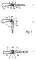
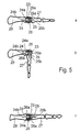
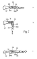
- Figures 1a-c to 7a-c illustrate in outlines the combinations of various rigid and elastic spacer parts and rigid and elastic fixation parts, of which combinations the joint prosthesis according to the invention can be composed of.
- the joint capsule connecting the bones to be joint together and surrounding the joint prosthesis is not included.
- the elastic spacer part is a cloth, string, or braiding 1 constructed of fibres and bent twice, and rigid fixation pins 2 and 3 function as fixation parts penetrating the hems of the spacer part 1, which hems are placed parallel with heads of bones 4 and 5 to be joint.
- the fixation pins 2 and 3 have stems 2a, 3a which are on the surface of the hems of the spacer part, and points 2b, 3b which are inside the bones 4 and 5 to be joint, longitudinally parallel with them.
- the elastic spacer part is a three dimensional form part 6 ("pillow") constructed of fibres
- the fixation parts are rigid fixation pins 7, 8 having stems 7a, 8a which are inside the spacer part, and points 7b, 8b which are inside bones 9 and 10 to be joint.
- the elastic spacer part is a three dimensional form part 11 ("pillow") according to Fig. 2.
- a first fixation part is a rigid pin 12 having a stem 12a which is inside the spacer part, and a point 12b which is inside a first bone 14 to be joint.
- a second fixation part is elastic and composed of three suture loops 13a, 13b and 13c, which are fixed in the spacer part 11 and a second bone 15 to be joint.
- the elastic spacer part is a three dimensional form part 16 ("pillow") according to Figs. 2 and 3.
- a first fixation part is a rigid pin 17 having a stem 17a which is inside the spacer part, and a point 17b which is inside a first bone 21 to be joint.
- a second fixation part is an elastic, elongated cloth 18 ("veil"), substantially of the same width as the spacer part 16, which cloth 18 is connected at its first hem to a spacer part 16, for example with sutures, and at its second hem to the second bone 22 to be joint, on its upper surface, with small dissolving pins 19, wherein the elastic cloth 18 is fixed, for example with stitches, on the lower surface of the spacer part 16, and directed with two foldings 20a and 20b to the second bone 22, in a corresponding manner as with the suture loops 13a, b, c of Fig. 3.
- the elastic spacer part is a three dimensional form part 23 ("pillow) according to Figs. 2 to 4.
- the fixation parts are rigid, elongated fixtures 24, 25, joint together by a hinge joint 26 or the like, and having points 24b, 25b which are inside bones 27 and 28 to be joint together.
- the stems 24a, 25b of the fixtures 24, 25 form hinge joint parts, which are inside the spacer part.
- the hinge joint has a biodegradable shaft 26a, which connects the stem parts 24a, 25a.
- the elastic, porous spacer part is a three dimensional form part 29 in accordance with Figs. 2 to 5.
- the form part 29 is penetrated by a fixation part 30, which forms a uniform bar or rod, which is elastic, at least where the spacer part 29 is situated, and having points 34a, 35a which are inside bones 36, 37 to be joint together.
- Fig. 7 illustrates an elastic, porous, blown spacer part 33, and elastic fixation parts 34, 35 formed in connection with and fixed to the spacer part 33, the fixation parts 34, 45 diverging from the spacer part 33 and having points 34a, 35a which are inside bones 36, 37 to be joint.
- Figs. 1 to 7 illustrate only some embodiments of the joint prosthesis according to the invention, in which a porous, elastic spacer part and rigid or elastic fixation parts are connected together to form the joint prosthesis of the invention.
- fixation parts to a bone, particularly of pin, screw, bolt or rod shaped fixation parts, it is possible to arrange a profiling on their surface.
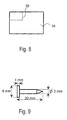
- a spacer part of about 10 x 15 x 5 mm was manufactured of a commercially available VICRYL-pillow [(use indication: to support Transversalis fascia in inguinal herniaplastics), measurements about 20 x 50 x 5 mm, manufacturer: ETHICON, Norderstedt, Germany] in the following manner: a seam 39 was sewn in the hernia pillow 38 with 3-0 bioabsorbing VICRYL thread, as illustrated in Fig. 8 (the pillow is illustrated as seen from above).
- co-polymer P( ⁇ -CUL-LA) of ⁇ -caprolactone and L-lactid As raw material for the spacer part there was used co-polymer P( ⁇ -CUL-LA) of ⁇ -caprolactone and L-lactid, the co-polymer having a monomer molar ratio of 25/75 and M ⁇ ⁇ 100 000 daltons.
- Tubular knitting was made of the fibre by a cylinder mould machine and a piece of a desired size was cut thereof.
- the knitting was folded to a multilayer, rectangular prism form in a manner that the shear edges were left inside the foldings. Subsequently, the foldings were fixed together by sewing them fixed at their edges, by using the same fibre the knitting had been made of. In this manner, a uniform spacer part constructed of fibres was obtained, having the measurements 10 x 16 x 5 mm.
- a biodegradable joint prosthesis according to Fig. 3 was manufactured in the following manner:
- a spacer part according to Example 2, provided with a pin of Example 3 and a veil of Fig. 4 was manufactured in the following manner:
- a two-folded piece of knitted veil was placed partially on top of the folded knitting and subsequently the both knittings were penetrated by a punching knife having the diameter of 3 mm.
- the pin was pressed through the hole in a manner that its stem remained on the surface of the knitting and its stalk was left outside the knitting.
- the knitting was folded in a manner that the veil part was at its one end outside the spacer part and at the other end inside the pillow.
- the edges of the foldings were sewn together by using the same fibre the knitting was made of.
- the final construction corresponds the Figure 4.
- a joint prosthesis according to Example 4 used as an artificial joint to replace a knuckle joint.
- a transverse skin opening was made at the knuckle joints.
- the starting point was the MCP II joint, where it was proceeded from an axial opening in the radial side of the extensor joints.
- synovectom of the joint was implemented.
- the damaged point part of metacarpus was resected from the distal size of the collateral ligaments (a piece of about half a centimetre in length corresponding the size of the final prosthesis). After this removal, synovectom was replenished.
- the ulnar collateral ligament and the joint capsule were released if necessary, at the side of the metacarpus, and the radial collateral ligament was tightened. If there, in addition to this, had been a volar subluxation in the joint, the joint capsule was mobilised also on the volar side in a manner that a good dynamic balance was obtained in the joint.
- Treating of the bone was started on the proximal phalanx side by making an aperture with a bone drill from the centre point of the joint surface to about 2 mm to the volar direction.
- the aperture was enlarged to correspond the size of the prosthesis by using a core rasp.
- a fit-joint stalk part which was of the right size was fitted in.
- the operation area was rinsed with care.
- the final prosthesis part was carried to its place by pushing the stalk of the pin tightly to the proximal phalanx in a manner that the spacer part which was to remain in the joint was in good contact with the joint surface of the proximal phalanx.
- the patient was allowed to start exercising the operated joint under the control of an occupational therapist as soon as on the second or third day after the operation; a so-called dynamic splint was manufactured to be used in day time and when performing the exercises.
- the object of the dynamic splint was also to maintain a good position in the fingers during the entire time it was to be used, that is a total of three months, during which time also a so-called rest splint was used during night time.
- Three months after the operation the patient was taken to the first re-control, wherein motion ranges of the joint, fault position of the fingers and pressing power was measured. Subsequently, the patient was given the permission to discard the splints and gradually to start using the hand in a normal manner.
- the fibrous joint functioned well, allowing flexion and extension of the knuckle joints and also giving the joints lateral stability together with the reconstructed lateral ligaments.
- a medial skin opening was made over the MTP I joint lengthways over the bunion.
- the joint capsule was opened lengthways, the proximal phalanx and the metatarsus 1 were prepared subperiostically.
- the bony prominence connected to the medial side of the MTP 1 was chiselled.
- a proximal part of about 5 mm was sawed from the proximal phalanx.
- a spacer part according to Example 2 was placed, the fixing of which was made with stitch material to the medial side of the proximal phalanx and metatarsus by means of stitches running through bone canals.
- the medial joint capsule was fixed through bone canals in order to avoid recidivum fault position (valgus).
- Supporting splints were manufactured for the patients, which splints were used 2 to 4 weeks by arthrosis patients, and about 6 weeks by rheumatism patients to maintain a good position. During this time, the patients were allowed to walk freely by using a partial shoe which was manufactured in a special manner so that the load is directed on the heel area, and not at all on the operated area.
- Six weeks after the operation the patients were taken to a re-control and they were given a permission to start taking normal exercises by using shoes with a more solid sole than in normal shoes.
- Six months after the operation the patients were taken to the final control, wherein an x-ray of the operated foot was taken, in which a fibrous interspace could be seen in the operated joint. In this context, the motion of the joint and the valgus angle of the remedied MTP I -joint were measured.
- Carpo-metacarpo 1 interposition arthoplasty
- the joint capsule was opened and it was detached subperiostically from the base of the CMC 1.
- On both joint surfaces a minimal resection was made in a manner that a proper pumiceous bone surface was shown.
- bone canals were made between the joint surfaces.
- the cut was continued in a manner that either extensor carpi radialis longus or palmaris longus joint was shown, from which 1/3 to 1/2 was taken, in as long a piece as possible, and this piece was transferred freely to the bone canal.
- the pillow formed spacer part made of PCL -copolymer fibre was used, having a permeable hole at its centre.
- the joint was taken through the hole at the centre of the spacer part, and tied dorsally extra-articulately fixed while the spacer part was fitted between the roughed joint surfaces.
- a longitudinal Kirschner spike was taken to carpal bones to the thumb radial abduction.
- the joint capsule was closed to the transplanted joint in order to obtain as good stability as possible.
- the Kirschner spike was removed after about four weeks and motion training is started.
Landscapes
- Health & Medical Sciences (AREA)
- Orthopedic Medicine & Surgery (AREA)
- Cardiology (AREA)
- Oral & Maxillofacial Surgery (AREA)
- Transplantation (AREA)
- Engineering & Computer Science (AREA)
- Biomedical Technology (AREA)
- Heart & Thoracic Surgery (AREA)
- Vascular Medicine (AREA)
- Life Sciences & Earth Sciences (AREA)
- Animal Behavior & Ethology (AREA)
- General Health & Medical Sciences (AREA)
- Public Health (AREA)
- Veterinary Medicine (AREA)
- Prostheses (AREA)
- Materials For Medical Uses (AREA)
Abstract
Description
- The present invention relates to a joint prosthesis as described in the preamble of
claim 1. - The document US-A-5 207 712, which can be considered as the closest prior art shows a device with all the features of the preamble of
claim 1. - In surgery, it is previously known to use synthetic, elastic joint implants made of non-biodegradable plastics to replace joints between small bones in hand and feet. A typical biostable elastic joint prosthesis is composed of (a) a spacer part placed between the bones to be joint, and of (b) a proximal and distal elongated fixation part which are placed inside the bones to be joint. This type of artificial joint include for example Silastic® implants made of silicon elastomer (Manufacturer: Dow Coming S.A., Valbourne Cedex, France).
- When inserting an artificial joint, one or both for example of rheumatism damaged joint surfaces are customarily removed partially or totally, and inside the joint capsule an elastic implant is placed to function as joint prosthesis for keeping the bones to be joint at a desired distance from each other, and allowing the joint to be bent by muscular powers. Artificial joint operations in hand, wrist and feet areas are described for example in the book "Surgery for Rheumatoid Arthritis," Eds. M. Clayton and C. Smyth, Churchill Livingstone, New York, 1992.
- However, the use of joint prostheses manufactured of biostable polymers, polymer mixtures and elastomeres may cause problems to the patient. A permanent strain limit for the operated limb has to be set. For example when Silastic® joint prostheses are used, the operated hand may be strained only with a burden of 5 kg. Overstraining may lead to breaking or wearing of the implant which forms the joint prosthesis.
- Furthermore, wearing and/or corrosion may cause that particles come loose of the biostable implant operating as joint prosthesis, which particles effect a chronic inflammation reaction, i.e. a synovitis, and/or osteological changes in the bone. Further, the inflammation reaction may cause tumefaction and pain in the joint even to the degree that the joint prosthesis has to be removed.
- It is the surprising discovery of the present invention that by manufacturing an elastic joint prosthesis, mainly according to the manner described in the characterizing part of the
claim 1, it is possible to eliminate the above described disadvantages related to prior art solutions and to substantially improve the level of technology applied in the field of surgically inserted joint prostheses, particularly the functionality and strength of the joint provided with a joint prosthesis, and to avoid harmful and chronic foreign substance reactions. It is possible to eliminate the above presented problems typical for biostable joint protheses by means of a joint prosthesis according to the invention, which joint prosthesis is manufactured of biodegradable polymer, co-polymer, polymer mixture or polymer composition in a manner that it is composed of (a) a porous interposition spacer part, and (b) a proximal fixation part fixed in the bones to be joint to each other, and (c) a distal fixation part. - A joint prosthesis in accordance with the invention can be inserted in the hand, wrist or feet area to replace the damaged joint entirely or partially. The porous spacer part of the prosthesis keeps the bones to be joint at a desired distance from each other. The spacer part is fixed in the bones to be joint by using a proximal and distal fixation part. The strength and ductility values of the fixation parts have been chosen to allow the bending of the operated joint shortly after the insertion operation.
- It is characteristic to the joint prosthesis of the present invention that, because the spacer part is porous and biodegradable, a fibrous tissue induces to form on its surface and inside it. Earlier research has discovered that biodegradable polymer implants induce around and inside themselves formation of fibrous tissue (cf. for example Sasserath, C.; Van Reck, J. Gitani, J., Acta. Stomatologica Belgica 88,
No 1, 1991, pp 5-11; and Ashammakhi, N., Mäkelä, E.A., Vihtonen, K., Rokkanen, P., Kuisma, H. and Törmälä, P., Biomaterials 16 (1995), pp. 135-138). - When a porous, biodegradable spacer part containing fibrous tissue continues to biodegrade (typically from 3 weeks to 12 months after the insertion operation, depending on its polymer construction), it is gradually replaced by elastic fibrous tissue which fills the space between the joint intermediate, filled originally by the spacer part, and is fixed in the bones to be joint. Simultaneously or partially after biodegrading of the spacer part also the proximal and distal fixation part go through a biodegrading process and are replaced by a fibrous tissue and/or bone tissue. As a result, a new, biological, elastic fibrous tissue joint , i.e. "a bioprosthesis," is obtained, which allows moving motion of the joint bones by muscular powers. As the new joint, i.e. the "bioprosthesis," is formed after the degradation process and replacing process of the joint prosthesis entirely of the patient's own tissue, no foreign substance particles harmful to the person's system can come loose, as is the case with a so-called biostable joint prosthesis. Thus, the joint prosthesis in accordance with the invention entirely eliminates the risks to such chronic complications caused by foreign substance particles which are possible when using biostable joint prostheses.
- The joint prosthesis according to the invention can be manufactured of biodegradable polymer, co-polymer, polymer mixture or composition, i.e. composition material, or by combining various biodegradable polymer substances. In medical, technical and patent literature a multitude of biodegradable polymers has been introduced which are suitable for raw materials of joint prostheses in accordance with the present invention. These include for example biodegradable alifatic polyesters (cf. for example Vainionpää, S., Rokkanen, P., and Törmälä, P. in Progr. Polym. Sci., 14 (1989), pp. 679-716; patent publications US-4-743 257; US-5-084 051; US-4-968 317; EPO 0423155, patent application PCT/F193/00014), polyester amids, polyorthoesters, polyanhybrids and polyphosphatsenes (cf. for example C.T. Laurensin et al., J. Biomed Mater. Res., 27 (1993), pp. 963-973).
- The porous spacer part of the joint prosthesis in accordance with the invention contains advantageously open porosity, with the pore size varying between 50 µm and 1000 µm. In case the pore size is substantially less than 50 µm, the fibrous tissue cells are not capable of growing inside the porosity. Thus, the spacer part may biodegrade from inside to the degree that it collapses at some stage, wherein the distance between the bones to be joint may become smaller than desired. If the spacer part pores have a larger diameter than 1000 µm, the fibrous tissue can of course grow to the pores, but the mechanic strength of the spacer part is not sufficient because of deteriorating strength due to large pore size.
- In order to obtain desired porosity (pore size typically between 50 µm and 1000 µm) in the spacer part, it can advantageously be constructed of biodegradable fibres (fibre thicknesses typically between 1 to 300 µ m), by manufacturing a fibre forming a three dimensional, partly porous structure. Manufacturing of structures of this type is known from mechanical textile technology. Biodegradable fibres can be used for weaving cloth or knitting tricot or for manufacturing non-woven cloth and folding or wrapping a three dimensional, pillow-like, porous spacer part of a construction of this type. It is also possible to use novel, three dimensional weaving, knitting or twisting techniques of fibre blank in order to manufacture a continuous fibre blank and to cut off suitable pieces for spacer part from such blank . Further, it is possible to bind together biodegradable broken fibres by using biodegradable binding blank to form a three dimensional spacer structure. It is obvious that also other manufacturing techniques by which porous structures are obtained of broken or continuous fibres are possible when the spacer part is constructed.
- The spacer part manufactured of fibres can be made of a single fibre type, such as polyglycolid, polylactid or poly-ε-caprolactone fibres. According to one advantageous embodiment, the spacer part can be manufactured to have a hybrid form by using rapidly degradable fibres and more slowly degradable fibres. A combination of this type is for example polyglycolid fibres + poly-L-lactid fibres (for example in relation 40/60). Thus, the polyglycolid fibres start to degrade rapidly and induce a strong fibrous tissue growth on the surface and inside the spacer part as soon as on the first week after the operation. More slowly absorbing poly-L-lactid fibres maintain the spacer part form for months and do not absorb until over a year, after the new fibrous tissue joint has been formed and healed to a significant degree.
- According to one embodiment, the spacer part can be manufactured of slowly absorbing fibres, which have been coated with a rapidly absorbing polymer. Poly-L-lactid fibres coated with poly-DL-lactid include in combinations of this type. A rapidly dissolving coating induces rapidly the forming of fibrous tissue around and inside the spacer part. More slowly dissolving poly-L-lactid fibres maintain the spacer part form for months and do not dissolve until over a year, after the new fibrous tissue joint has been formed and healed to a significant degree.
- The spacer part can also be manufactured of biodegradable, continuos-constructed polymer blank by producing porosity therein. Porous material of this type can be manufactured for example by mixing blowing agent to biodegradable polymer powder or granulate. The blowing agent degrades or evaporates in connection with the melting of the polymer and forms pores (bubbles). Porous biomaterial of this type can be manufactured by extrusion or feeder casting, and spacer pieces of desired size can be cut from the porous blank. Further, by feeder casting it is possible to make spacer pieces of directly the desired size.
- Moreover, in plastics technology, a plurality of other methods is known to obtain porosity in a polymer piece. It is possible for example during smelting treatment to mix to the biodegradable polymer some additive in powder form, such as some salt, cane sugar etc., which can be absorbed from the ready-made blank by using a suitable absorbent, such as water, and by using this method to provide open porosity in the blank. An other option is to leave the additive in the spacer part, wherein it under tissue conditions after the surgical operation, metabolises and in the spacer part develops porosity which is characteristic to it. Furthermore, supercritical carbon dioxide or other gas in over pressure can be absorbed in the biodegradable polymer blank and blow the blank by using this gas when the pressure is lowered. It is obvious that also other methods for obtaining open porosity to the biodegradable polymer blank are possible when manufacturing the spacer part.
- It is advantageous to the spacer part that its form corresponds to the space between the bones to be joint where the spacer part is positioned. Thus, the spacer part can have typically the form of a pillow, cylinder, ellipsoid, (flattened) ball, cubic or rectangular prism, or other three dimensional structure which as well as possible fills the space constructed for the spacer part between the bones to be joint. The spacer part is advantageously elastic and it may not contain any sharp and/or hard edges or angles which could cause mechanic irritation in the tissue.
- The spacer part may have a rigid structure, wherein it does not to any significant extent change its form when the joint is bent. In this situation, the fixation parts has to be flexible and elastic at least for those parts which are situated between the bones and the spacer part, so that the joint can be moved and, in case also the fixation parts are rigid, the spacer part and the fixation parts have to be fixed together by using a flexible joint, for example a hinge joint.
- If the spacer part is flexible, both flexible and rigid fixation parts can be connected thereto.
- The spacer part and the proximal and distal fixation part can be composed of the same biodegradable material (thus, also the fixation parts can possibly contain open porosity, which may fasten the fixation of the fixation parts into the bone due to tissue growth, which is based on porosity) or they may be manufactured as separate parts and connected to each other either before the inserting operation or during the inserting operation to form a flexible and/or elastic entity.
- The fixation parts of the joint prosthesis in accordance with the present invention are characterized in that they are joint to the spacer part to form a fixed and integrated entity in a manner that the fixation parts and the spacer part together form a flexible joint prosthesis. By means of the fixation parts, the spacer part is kept between the bones to be joint, wherein by means of muscular power it is possible to bend also the bones to be joint (bending movement of the joints) in relation to each other.
- The fixation part can be manufactured of biodegradable polymer, polymer mixture or composition by using a smelting treatment method, such as feeder casting or extrusion, or it can be treated mechanically of a polymer blank or of a piece to a desired form.
- Self-reinforced biodegradable compositions are particularly advantageous compositions for raw materials of the fixation parts in accordance with the invention. Compositions of this type have been described in publications US-4-743257 and WO-88/05312. Also biodegradable compositions of a different type are possible when manufacturing fixation parts according to the invention. Thus, they can be made by reinforcing the biodegradable material by fibres, split fibres, filaments or structures constructed thereof, such as braidings, threads, strings, non-woven structures, cloths, knittings etc. made of biodegradable polymer, co-polymer or polymer mixture, by combining ready-made fibres with a suitable matrix of polymers. Fibres of this type can be manufactured for example of many polymers mentioned in the reference publications of this invention.
- Reinforced fibres of the fixation part can also be biodegradable ceramic fibres, such as biofibreglass or calcium phosphate fibres (cf. for example Vainionpää, S., Rokkanen P., and Törmälä P. in Prog. Polym. Sci., 14 (1989), pp. 679-716).
- Fixation parts in accordance with the invention, which are reinforced by biodegradable organic and/or inorganic fibres or structures constructed thereof, can be manufactured by means of different methods in plastics technology by binding the reinforced structures, at least partially, to each other by absorbing polymer, co-polymer or polymer mixture (matrix) under conditions in which, normally when the matrix is in solution or smelt form, a sufficiently homogeneous composition is formed of the matrix and the reinforcing agent. Injection moulding, extrusion, pultrusion, winding, and compression moulding are some possible methods to be used when combining the reinforcing fibres or the like and the matrix, and when forming them into prefabricates and/or instruments.
- If desired, also the fixation parts can include open porosity in a similar manner as the spacer part, wherein tissue growth takes place in the open porosity of the fixation part from the surrounding tissue, and as a result of this the fixation part is rapidly locked in its place.
- It is obvious, that the implants of the invention may also include various additives to facilitate the processability of the material (for example stabilizers, antioxidants, or softening agents) or to change its properties (for example softening agents or ceramic chemicals in powder form or biostable fibres, such as carbon fibres) or to facilitate its treating (for example colouring agents).
- The fixation part can also be constructed of the patient's own fibrous tissue, such as cord or ligament tissue, by placing a sufficiently long part of a cord or ligament to extend from one bone to be joint to the other, in a manner that the spacer part is placed between the bones and the cord or ligament penetrates the spacer part.
- According to one advantageous embodiment, the spacer part and/or the fixation parts of the invention contain a bioactive agent or agents, such as antibiotics, chemotherapeutic agents, agents accelerating wound healing, agents inducing forming of cartilage collagen, growth hormones, anticoagulant (such as heparin), etc. Bioactive mediums of this type are particularly advantageous in clinical use, because, in addition to the mechanic affect, they have biochemical affects (for example accelerating the growth of fibrous tissue), medical and other effects in human tissues.
- The fixation parts can have a rigid or flexible structure. A rigid fixation part is typically a rod, bar, screw or pin, which is at its stem part connected to the spacer part and whose point is inside the bone to be joint. A profiling (such as a screw thread, various scales or steps) on the surface of a fixation part of this type facilitate the fixation part to lock into the hole made inside the bone. The elastic fixation part can be for example a cloth ("a veil") coming out of the spacer part and fixed with small absorbing pins or a suture on the surface of the bone to be joint. The elastic fixation part can also be composed of two or several loops of the absorbing suture which are used for fixing the spacer part to the bone to be joint.
- The invention is described in the following description with reference to the examples illustrated in accompanying drawings, in which
- Figs. 1 to 7
- 'illustrate in a schematic longitudinal chart some applications
of the joint prosthesis according to the invention to be used
for jointing together small bones (such as hand and feet
bones), wherein each Figure 1 to 7 comprises partial Figures
a, b, c in a manner that the partial Figure
- a) is a schematic chart parallel with the longitudinal axis of the bones, as seen from the side, i.e. from the perpendicular direction against the bending level of the joint, the joint provided with a joint prosthesis being straight,
- b) is a schematic chart parallel with the longitudinal axis of the bones, as seen from the side, i.e. from the perpendicular direction against the bending level of the joint, the joint provided with a joint prosthesis being bent, and
- c) is a schematic chart parallel with the longitudinal axis of the bones, as seen from above, i.e. from the direction of the bending level of the joint, the joint provided with a joint prosthesis being straight,
- Fig. 8
- illustrates a spacer part application according to Example 1, and
- Fig. 9
- illustrates a fixation part according to Example 3, as seen from the side.
- Figures 1a-c to 7a-c illustrate in outlines the combinations of various rigid and elastic spacer parts and rigid and elastic fixation parts, of which combinations the joint prosthesis according to the invention can be composed of. In order to simplify the schematic charts, the joint capsule connecting the bones to be joint together and surrounding the joint prosthesis is not included.
- In Fig. 1 the elastic spacer part is a cloth, string, or
braiding 1 constructed of fibres and bent twice, andrigid fixation pins spacer part 1, which hems are placed parallel with heads ofbones points bones - In Fig. 2 the elastic spacer part is a three dimensional form part 6 ("pillow") constructed of fibres, and the fixation parts are
rigid fixation pins points bones - In Fig. 3 the elastic spacer part is a three dimensional form part 11 ("pillow") according to Fig. 2. A first fixation part is a
rigid pin 12 having astem 12a which is inside the spacer part, and apoint 12b which is inside afirst bone 14 to be joint. A second fixation part is elastic and composed of threesuture loops 13a, 13b and 13c, which are fixed in thespacer part 11 and asecond bone 15 to be joint. - In Fig. 4 the elastic spacer part is a three dimensional form part 16 ("pillow") according to Figs. 2 and 3. A first fixation part is a
rigid pin 17 having astem 17a which is inside the spacer part, and apoint 17b which is inside afirst bone 21 to be joint. A second fixation part is an elastic, elongated cloth 18 ("veil"), substantially of the same width as thespacer part 16, whichcloth 18 is connected at its first hem to aspacer part 16, for example with sutures, and at its second hem to thesecond bone 22 to be joint, on its upper surface, with small dissolving pins 19, wherein theelastic cloth 18 is fixed, for example with stitches, on the lower surface of thespacer part 16, and directed with twofoldings second bone 22, in a corresponding manner as with thesuture loops 13a, b, c of Fig. 3. - In Fig. 5 the elastic spacer part is a three dimensional form part 23 ("pillow) according to Figs. 2 to 4. The fixation parts are rigid,
elongated fixtures points bones fixtures biodegradable shaft 26a, which connects thestem parts - In Fig. 6 the elastic, porous spacer part is a three
dimensional form part 29 in accordance with Figs. 2 to 5. Theform part 29 is penetrated by afixation part 30, which forms a uniform bar or rod, which is elastic, at least where thespacer part 29 is situated, and havingpoints bones - Fig. 7 illustrates an elastic, porous,
blown spacer part 33, andelastic fixation parts spacer part 33, thefixation parts 34, 45 diverging from thespacer part 33 and havingpoints bones - It is obvious, that Figs. 1 to 7 illustrate only some embodiments of the joint prosthesis according to the invention, in which a porous, elastic spacer part and rigid or elastic fixation parts are connected together to form the joint prosthesis of the invention.
- To improve the fixing of fixation parts to a bone, particularly of pin, screw, bolt or rod shaped fixation parts, it is possible to arrange a profiling on their surface.
- The functionality of the invention has been described by means of the following non-restrictive examples.
- Manufacturing of the spacer part (pillow) of a commercially available, biodegradable VICRYL hernia pillow:
- A spacer part of about 10 x 15 x 5 mm was manufactured of a commercially available VICRYL-pillow [(use indication: to support Transversalis fascia in inguinal herniaplastics), measurements about 20 x 50 x 5 mm, manufacturer: ETHICON, Norderstedt, Germany] in the following manner: a
seam 39 was sewn in thehernia pillow 38 with 3-0 bioabsorbing VICRYL thread, as illustrated in Fig. 8 (the pillow is illustrated as seen from above). - Subsequently, the area restricted by the
seam 39 was cut off from the original VICRYL-pillow outside the seam, wherein there was obtained a new smaller pillow (measurements about 10 x 15 x 5 mm), suitable for the spacer part of the invention. - Manufacturing of the spacer part of biodegradable co-polymer of L-lactid and ε-caprolactone:
- As raw material for the spacer part there was used co-polymer P(ε-CUL-LA) of ε-caprolactone and L-lactid, the co-polymer having a monomer molar ratio of 25/75 and Mν ∼ 100 000 daltons.
- Fibre of co-polymer was manufactured by using a single-screw extruder (Axon, Sweden), in which the polymer smelt (T = 140 to 170°C) was extruded through a single-hole (
diameter 1 mm) nozzle. After the cooling phase, the obtained monofilament was oriented freely in two phases at a raised temperature. The draw ratio in orientation was 8 to 10. The final fibre diameter was 150 µm. - Tubular knitting was made of the fibre by a cylinder mould machine and a piece of a desired size was cut thereof. The knitting was folded to a multilayer, rectangular prism form in a manner that the shear edges were left inside the foldings. Subsequently, the foldings were fixed together by sewing them fixed at their edges, by using the same fibre the knitting had been made of. In this manner, a uniform spacer part constructed of fibres was obtained, having the measurements 10 x 16 x 5 mm.
- A biodegradable joint prosthesis according to Fig. 3 was manufactured in the following manner:
- (A) A fixation part of Fig. 9 was manufactured of P(ε-CL/L-LA) co-polymer
50/50 (Mν ∼ 100 00 daltons) by feeder casting, the fixation part
having the following measurements: diameter of the stalk of the
fixation part 3 mm, total length of thefixation part 20 mm, diameter of thestem 6 mm, and thickness of thestem 1 mm. - (B) A spacer part (measurements 10 x 15 x 5 mm) was used, which had been manufactured in accordance with Example 1. A 10 mm long cut, parallel with the long sides of the spacer part was made in the surface knitting in the other side of the spacer part, and the fixation pin in accordance with the paragraph (A) was pressed from the cut inside the spacer part in a manner that the point and stalk of the fixation pin penetrated the spacer part and came out through the other surface of the spacer part. The fixation pin was pressed deep enough inside the spacer part for the broad stem to penetrate inside the spacer part to mix with the broken fibre therein. The cut was closed with 3-0 VICRYL-thread. The combination of the spacer part and fixation part was closed in a porous sterilization bag and it was sterilised with ethene oxide.
- (C) In an operation situation, in the other edge of the spacer part it was fixed by sewing 3 pieces of 3-0 VICRYL-threads to function as a second fixation part in accordance with Fig. 3. These threads were further fixed to the bone to be joint, as illustrated in Fig. 3.
-
- A spacer part according to Example 2, provided with a pin of Example 3 and a veil of Fig. 4 was manufactured in the following manner:
- A two-folded piece of knitted veil was placed partially on top of the folded knitting and subsequently the both knittings were penetrated by a punching knife having the diameter of 3 mm. The pin was pressed through the hole in a manner that its stem remained on the surface of the knitting and its stalk was left outside the knitting. Subsequently, the knitting was folded in a manner that the veil part was at its one end outside the spacer part and at the other end inside the pillow. The edges of the foldings were sewn together by using the same fibre the knitting was made of. The final construction corresponds the Figure 4.
- A joint prosthesis according to Example 4 used as an artificial joint to replace a knuckle joint.
- A transverse skin opening was made at the knuckle joints. The starting point was the MCP II joint, where it was proceeded from an axial opening in the radial side of the extensor joints. At first, synovectom of the joint was implemented. Subsequently, by means of a saw the damaged point part of metacarpus was resected from the distal size of the collateral ligaments (a piece of about half a centimetre in length corresponding the size of the final prosthesis). After this removal, synovectom was replenished. In case there had been an ulnar deviate position of the fingers, the ulnar collateral ligament and the joint capsule were released if necessary, at the side of the metacarpus, and the radial collateral ligament was tightened. If there, in addition to this, had been a volar subluxation in the joint, the joint capsule was mobilised also on the volar side in a manner that a good dynamic balance was obtained in the joint.
- Treating of the bone was started on the proximal phalanx side by making an aperture with a bone drill from the centre point of the joint surface to about 2 mm to the volar direction. The aperture was enlarged to correspond the size of the prosthesis by using a core rasp. A fit-joint stalk part which was of the right size was fitted in. Subsequently, the operation area was rinsed with care. The final prosthesis part was carried to its place by pushing the stalk of the pin tightly to the proximal phalanx in a manner that the spacer part which was to remain in the joint was in good contact with the joint surface of the proximal phalanx. Subsequently, in the dorsal side of the distal part of the metacarpus, there was drilled two or three holes having the diameter of 1 mm. The veil like part of the artificial joint was fixed with resorbing pins (Biofix® Mini-tack, manufacturer Biocon Oy, Tampere, Finland) at its place in the bone, after the joint had been reduced from the volar subluxation position to the normal position. Before the pins were fixed, also the ulnar collateral ligament was fixed in order to gain ligament balance of the joint which was more distal than the original one. Finally, centralisation of the extensor joints was implemented at the centre of the joint by closing the extended radial retinaculum by duplicating. The resulted situation is shown in Fig. 4.
- The patient was allowed to start exercising the operated joint under the control of an occupational therapist as soon as on the second or third day after the operation; a so-called dynamic splint was manufactured to be used in day time and when performing the exercises. The object of the dynamic splint was also to maintain a good position in the fingers during the entire time it was to be used, that is a total of three months, during which time also a so-called rest splint was used during night time. Three months after the operation the patient was taken to the first re-control, wherein motion ranges of the joint, fault position of the fingers and pressing power was measured. Subsequently, the patient was given the permission to discard the splints and gradually to start using the hand in a normal manner. In a re-control, 12 months after the operation, the fibrous joint functioned well, allowing flexion and extension of the knuckle joints and also giving the joints lateral stability together with the reconstructed lateral ligaments.
- The interposition arthoplasty of the MTP I joint by means of joint prosthesis according to Example 2:
- A medial skin opening was made over the MTP I joint lengthways over the bunion. The joint capsule was opened lengthways, the proximal phalanx and the
metatarsus 1 were prepared subperiostically. The bony prominence connected to the medial side of theMTP 1 was chiselled. Subsequently, a proximal part of about 5 mm was sawed from the proximal phalanx. In the created space, a spacer part according to Example 2 was placed, the fixing of which was made with stitch material to the medial side of the proximal phalanx and metatarsus by means of stitches running through bone canals. Also the medial joint capsule was fixed through bone canals in order to avoid recidivum fault position (valgus). - Supporting splints were manufactured for the patients, which splints were used 2 to 4 weeks by arthrosis patients, and about 6 weeks by rheumatism patients to maintain a good position. During this time, the patients were allowed to walk freely by using a partial shoe which was manufactured in a special manner so that the load is directed on the heel area, and not at all on the operated area. Six weeks after the operation the patients were taken to a re-control and they were given a permission to start taking normal exercises by using shoes with a more solid sole than in normal shoes. Six months after the operation the patients were taken to the final control, wherein an x-ray of the operated foot was taken, in which a fibrous interspace could be seen in the operated joint. In this context, the motion of the joint and the valgus angle of the remedied MTP I -joint were measured.
- A longitudinal cut was made on
CMC 1 and the joint capsule was revealed between the joints by taking care of the ramifications of the radial artery and nerve. The joint capsule was opened and it was detached subperiostically from the base of theCMC 1. On both joint surfaces a minimal resection was made in a manner that a proper pumiceous bone surface was shown. Subsequently, bone canals were made between the joint surfaces. The cut was continued in a manner that either extensor carpi radialis longus or palmaris longus joint was shown, from which 1/3 to 1/2 was taken, in as long a piece as possible, and this piece was transferred freely to the bone canal. The pillow formed spacer part made of PCL -copolymer fibre was used, having a permeable hole at its centre. The joint was taken through the hole at the centre of the spacer part, and tied dorsally extra-articulately fixed while the spacer part was fitted between the roughed joint surfaces. Subsequently, through the base of the CMC 1 a longitudinal Kirschner spike was taken to carpal bones to the thumb radial abduction. The joint capsule was closed to the transplanted joint in order to obtain as good stability as possible. The Kirschner spike was removed after about four weeks and motion training is started. - It is to be noted that the above mentioned literary sources present a multitude of materials which are suitable for materials in the joint prosthesis in accordance of the invention, in respect of both strength and biodegradable properties. According to these literal and research references, by using the above presented example series as an analog basis, a man skilled in the art can, by applying his or her knowledge in polymers, plastic technology, medicine and surgery, perform the corresponding experiments and testings and prove the functionality of the invention also for other applicable polymers, co-polymers, polymer mixtures and/or compositions known to a man skilled in the art.
Claims (13)
- A joint prosthesis intended to be mounted between two bones to be joint together, wherein the joint prosthesis comprisescharacterized in that the spacer part (1, 6, 11, 16, 23, 29) and the fixation part (2, 3; 7, 8; 13a,b,c, 12; 17, 18; 24, 25; 30) is manufactured in separate pieces of one or several biodegradable polymers, co-polymers, polymer mixtures and/or composites and fixed together in order to form a joint prosthesis, and that the spacer part (1, 6, 11, 16, 23, 29) is a three-dimensional, uniform form piece which is formed, at least under tissue conditions, to be porous in a manner that the construction comprises continuos and/or broken fibres.a spacer part (1, 6, 11, 16, 23, 29,)intended to be placed between the joint surfaces of the bones to be joint, and whichis manufactured of biodegradable polymer, co-polymer, polymer mixture and/or composite, andfixation parts (2, 3; 7, 8; 13a,b,c, 12; 17, 18; 24, 25; 30) whichare arranged to fix the spacer part (1, 6, 11, 16, 23, 29) to the bones to be joint,
- A joint prosthesis as set forth in claim 1, characterized in that the spacer part (6,11,16, 23, 29, 33) is a form piece having the form of a pillow, cylinder, ellipsoid, (flattened) ball, cubic or rectangular prism.
- A joint prosthesis as set forth in claim 1, characterized in that the spacer part (1) is a string, braiding, cloth, pillow, or non-woven felt.
- A joint prosthesis as set forth in any of the claims 1 to 3, characterized in that at least one of the fixation parts (13a,b,c; 18) is composed, at least partially, of at least one thread, braiding or cloth constructed of fibre.
- A joint prosthesis as set forth in claims 1 to 4, characterized in that at least one of fixation parts (2, 3; 7, 8; 12; 17, 18; 24, 25; 30; 34, 35) is formed at least partially of one rigid pin, screw, bolt or rod, wherein the stem of the fixation part (2, 3; 7, 8; 12; 17, 18; 24, 25; 30; 34, 35) is preferably situated inside or on the outer surface of the spacer part (1, 6, 11, 16, 23, 29, 33).
- A joint prosthesis as set forth in claims 1 to 5, characterized in that fixation parts (24, 25) are joint (24a, 24b) together preferably inside the spacer part (23).
- A joint prosthesis as set forth in claims 1 to 6, characterized in that fixation parts (30) form at least one uniform, at least partially elastic bar or string which is preferably directed through the spacer part to extend to the bones to be joint.
- A joint prosthesis as set forth in any of the claims 4 to 7, characterized in that at least one fixation part is at least partially profiled on its surface.
- A joint prosthesis as set forth in any of the claims 4 to 8, characterized in that at least one of the fixation parts is constructed of the patient's own fibrous tissue, such as cord or ligament.
- A joint prosthesis as set forth in claim 1, characterized in that the fixation parts (2, 3; 7, 8; 12, 17, 18; 24, 25; 30; 34, 35) are manufactured of biodegradable polymer, co-polymer, polymer mixture and/or composite.
- A joint prosthesis as set forth in claim 1, characterized in that the porosity of the spacer part (1, 6, 11, 16, 23, 29, 33) is between 50 µm and 1000 µm.
- A joint prosthesis as set forth in any of the claims 1 to 3, characterized in that the spacer part is a composite structure comprising at least two compounds, the structure comprising materials with different degrading times under tissue conditions, wherein the construction of the spacer part is formed by coating a polymer or the like which degrades slower under tissue conditions with a polymer which degrades faster under tissue conditions, and/or by forming the spacer part of polymers or the like having the above mentioned properties in mixture, for example in fibre form.
- A joint prosthesis as set forth in any of the claims 1 to 3, characterized in that the spacer part (1, 6, 11, 16, 23, 29, 33) is formed of biodegradable fibres having a typical fibre thickness of 1 to 300 µm.
Applications Claiming Priority (3)
| Application Number | Priority Date | Filing Date | Title |
|---|---|---|---|
| FI952884 | 1995-06-13 | ||
| FI952884A FI101933B (en) | 1995-06-13 | 1995-06-13 | Joint prosthesis |
| PCT/FI1996/000351 WO1996041596A1 (en) | 1995-06-13 | 1996-06-13 | Joint prosthesis |
Publications (2)
| Publication Number | Publication Date |
|---|---|
| EP0831757A1 EP0831757A1 (en) | 1998-04-01 |
| EP0831757B1 true EP0831757B1 (en) | 2001-11-28 |
Family
ID=8543589
Family Applications (1)
| Application Number | Title | Priority Date | Filing Date |
|---|---|---|---|
| EP96918708A Expired - Lifetime EP0831757B1 (en) | 1995-06-13 | 1996-06-13 | Joint prosthesis |
Country Status (8)
| Country | Link |
|---|---|
| US (1) | US6007580A (en) |
| EP (1) | EP0831757B1 (en) |
| JP (1) | JP2000515772A (en) |
| AU (1) | AU708260B2 (en) |
| CA (1) | CA2217291C (en) |
| DE (1) | DE69617423T2 (en) |
| FI (1) | FI101933B (en) |
| WO (1) | WO1996041596A1 (en) |
Cited By (4)
| Publication number | Priority date | Publication date | Assignee | Title |
|---|---|---|---|---|
| US8715325B2 (en) | 2009-02-19 | 2014-05-06 | Nextremity Solutions, Inc. | Bone joining apparatus and method |
| US9072562B2 (en) | 2009-02-19 | 2015-07-07 | Nextremity Solutions, Inc. | Bone joining device, kit and method |
| US9468465B2 (en) | 2009-02-19 | 2016-10-18 | Nextremity Solutions, Inc. | Reversible bone coupling device and method |
| US11660133B2 (en) | 2018-10-26 | 2023-05-30 | Zimmer, Inc. | Bone coupling device and method |
Families Citing this family (147)
| Publication number | Priority date | Publication date | Assignee | Title |
|---|---|---|---|---|
| US6371985B1 (en) * | 1995-03-09 | 2002-04-16 | Robert S. Goldberg | Prostheses restrained by immediate attachment while ingrowth proceeds naturally over time |
| US5718717A (en) | 1996-08-19 | 1998-02-17 | Bonutti; Peter M. | Suture anchor |
| US20050143734A1 (en) * | 1996-11-12 | 2005-06-30 | Cachia Victor V. | Bone fixation system with radially extendable anchor |
| US6632224B2 (en) | 1996-11-12 | 2003-10-14 | Triage Medical, Inc. | Bone fixation system |
| US5893850A (en) | 1996-11-12 | 1999-04-13 | Cachia; Victor V. | Bone fixation device |
| US6648890B2 (en) | 1996-11-12 | 2003-11-18 | Triage Medical, Inc. | Bone fixation system with radially extendable anchor |
| US6017366A (en) * | 1997-04-18 | 2000-01-25 | W. L. Gore & Associates, Inc. | Resorbable interposition arthroplasty implant |
| US6113640A (en) | 1997-06-11 | 2000-09-05 | Bionx Implants Oy | Reconstructive bioabsorbable joint prosthesis |
| AU7635198A (en) * | 1997-06-18 | 1999-01-04 | Andre Bahler | Endoprosthesis for a joint, in particular a finger, toe or wrist joint |
| US6692499B2 (en) | 1997-07-02 | 2004-02-17 | Linvatec Biomaterials Oy | Surgical fastener for tissue treatment |
| US6306426B1 (en) | 1997-08-11 | 2001-10-23 | Allergan Sales, Inc. | Implant device with a retinoid for improved biocompatibility |
| US6001100A (en) * | 1997-08-19 | 1999-12-14 | Bionx Implants Oy | Bone block fixation implant |
| US7541049B1 (en) | 1997-09-02 | 2009-06-02 | Linvatec Biomaterials Oy | Bioactive and biodegradable composites of polymers and ceramics or glasses and method to manufacture such composites |
| US6045551A (en) | 1998-02-06 | 2000-04-04 | Bonutti; Peter M. | Bone suture |
| US5984966A (en) * | 1998-03-02 | 1999-11-16 | Bionx Implants Oy | Bioabsorbable bone block fixation implant |
| US6221075B1 (en) | 1998-03-06 | 2001-04-24 | Bionx Implants Oy | Bioabsorbable, deformable fixation plate |
| US6319264B1 (en) | 1998-04-03 | 2001-11-20 | Bionx Implants Oy | Hernia mesh |
| US6086593A (en) | 1998-06-30 | 2000-07-11 | Bonutti; Peter M. | Method and apparatus for use in operating on a bone |
| US6099531A (en) | 1998-08-20 | 2000-08-08 | Bonutti; Peter M. | Changing relationship between bones |
| US6406498B1 (en) | 1998-09-04 | 2002-06-18 | Bionx Implants Oy | Bioactive, bioabsorbable surgical composite material |
| US6398814B1 (en) | 1998-09-14 | 2002-06-04 | Bionx Implants Oy | Bioabsorbable two-dimensional multi-layer composite device and a method of manufacturing same |
| US6350284B1 (en) | 1998-09-14 | 2002-02-26 | Bionx Implants, Oy | Bioabsorbable, layered composite material for guided bone tissue regeneration |
| US6520996B1 (en) * | 1999-06-04 | 2003-02-18 | Depuy Acromed, Incorporated | Orthopedic implant |
| US6447516B1 (en) | 1999-08-09 | 2002-09-10 | Peter M. Bonutti | Method of securing tissue |
| US6368343B1 (en) | 2000-03-13 | 2002-04-09 | Peter M. Bonutti | Method of using ultrasonic vibration to secure body tissue |
| US6533454B1 (en) | 1999-09-30 | 2003-03-18 | Bionx Implants Oy | Surgical system for tissue fixation |
| US6635073B2 (en) | 2000-05-03 | 2003-10-21 | Peter M. Bonutti | Method of securing body tissue |
| US9138222B2 (en) | 2000-03-13 | 2015-09-22 | P Tech, Llc | Method and device for securing body tissue |
| US7094251B2 (en) | 2002-08-27 | 2006-08-22 | Marctec, Llc. | Apparatus and method for securing a suture |
| ITVI20000025U1 (en) * | 2000-04-07 | 2001-10-07 | Tecres Spa | TEMPORARY SPACER DEVICE FOR SURGICAL TREATMENT OF THE KNEE |
| DE10046119A1 (en) * | 2000-09-15 | 2002-03-28 | Inst Textil & Faserforschung | Medical bioresorbable implant, method of manufacture and use |
| SE525131C2 (en) * | 2001-01-15 | 2004-12-07 | Artimplant Ab | Implants for reconstruction of joints |
| US7497874B1 (en) | 2001-02-23 | 2009-03-03 | Biomet Manufacturing Corp. | Knee joint prosthesis |
| US20020120340A1 (en) | 2001-02-23 | 2002-08-29 | Metzger Robert G. | Knee joint prosthesis |
| US6511481B2 (en) | 2001-03-30 | 2003-01-28 | Triage Medical, Inc. | Method and apparatus for fixation of proximal femoral fractures |
| US6887243B2 (en) | 2001-03-30 | 2005-05-03 | Triage Medical, Inc. | Method and apparatus for bone fixation with secondary compression |
| US6685706B2 (en) | 2001-11-19 | 2004-02-03 | Triage Medical, Inc. | Proximal anchors for bone fixation system |
| US20030097180A1 (en) * | 2001-11-20 | 2003-05-22 | Pertti Tormala | Joint prosthesis |
| US6719765B2 (en) | 2001-12-03 | 2004-04-13 | Bonutti 2003 Trust-A | Magnetic suturing system and method |
| US9155544B2 (en) | 2002-03-20 | 2015-10-13 | P Tech, Llc | Robotic systems and methods |
| EP1369094B1 (en) * | 2002-05-31 | 2014-11-26 | Zimmer GmbH | Implant and method of manufacturing a sterile packaged implant |
| US6793678B2 (en) | 2002-06-27 | 2004-09-21 | Depuy Acromed, Inc. | Prosthetic intervertebral motion disc having dampening |
| US20040006146A1 (en) * | 2002-07-06 | 2004-01-08 | Evans Douglas G. | Resorbable structure for treating and healing of tissue defects |
| US7049348B2 (en) * | 2002-07-06 | 2006-05-23 | Kensey Nash Corporation | Resorbable structure for treating and healing of tissue defects |
| WO2004008949A2 (en) | 2002-07-19 | 2004-01-29 | Triage Medical, Inc. | Method and apparatus for spinal fixation |
| US20040068262A1 (en) * | 2002-10-02 | 2004-04-08 | Mark Lemos | Soft tissue fixation implant |
| US20040138683A1 (en) | 2003-01-09 | 2004-07-15 | Walter Shelton | Suture arrow device and method of using |
| US7070601B2 (en) | 2003-01-16 | 2006-07-04 | Triage Medical, Inc. | Locking plate for bone anchors |
| US9445901B2 (en) * | 2003-03-12 | 2016-09-20 | Deger C. Tunc | Prosthesis with sustained release analgesic |
| US7497864B2 (en) | 2003-04-30 | 2009-03-03 | Marctec, Llc. | Tissue fastener and methods for using same |
| WO2004098453A2 (en) | 2003-05-06 | 2004-11-18 | Triage Medical, Inc. | Proximal anchors for bone fixation system |
| FR2863867B1 (en) * | 2003-12-22 | 2007-05-04 | Memometal Technologies | INTERPHALANGIAN AND / OR METACARPOPHALANGIAN PROSTHESIS |
| US8328876B2 (en) | 2003-12-31 | 2012-12-11 | Warsaw Orthopedic, Inc. | Bone matrix compositions and methods |
| US9504583B2 (en) * | 2004-06-10 | 2016-11-29 | Spinal Elements, Inc. | Implant and method for facet immobilization |
| US9463012B2 (en) | 2004-10-26 | 2016-10-11 | P Tech, Llc | Apparatus for guiding and positioning an implant |
| US9173647B2 (en) | 2004-10-26 | 2015-11-03 | P Tech, Llc | Tissue fixation system |
| US9271766B2 (en) | 2004-10-26 | 2016-03-01 | P Tech, Llc | Devices and methods for stabilizing tissue and implants |
| US20060089646A1 (en) | 2004-10-26 | 2006-04-27 | Bonutti Peter M | Devices and methods for stabilizing tissue and implants |
| US9089323B2 (en) | 2005-02-22 | 2015-07-28 | P Tech, Llc | Device and method for securing body tissue |
| FR2884406B1 (en) | 2005-04-14 | 2008-10-17 | Memometal Technologies Soc Par | INTRAMEDULAR OSTEOSYNTHESIS DEVICE OF TWO BONE PARTS, IN PARTICULAR HAND AND / OR FOOT |
| FI20055304L (en) * | 2005-06-13 | 2007-02-20 | Bioretec Oy | A bioabsorbable implant with variable properties |
| US20070021839A1 (en) * | 2005-07-21 | 2007-01-25 | William Lowe | Trapezium prosthesis and method |
| CN101365499A (en) | 2005-11-01 | 2009-02-11 | 骨骼技术股份有限公司 | Bone matrix compositions and methods |
| US11253296B2 (en) | 2006-02-07 | 2022-02-22 | P Tech, Llc | Methods and devices for intracorporeal bonding of implants with thermal energy |
| US11278331B2 (en) | 2006-02-07 | 2022-03-22 | P Tech Llc | Method and devices for intracorporeal bonding of implants with thermal energy |
| US8496657B2 (en) | 2006-02-07 | 2013-07-30 | P Tech, Llc. | Methods for utilizing vibratory energy to weld, stake and/or remove implants |
| US7967820B2 (en) | 2006-02-07 | 2011-06-28 | P Tech, Llc. | Methods and devices for trauma welding |
| US11246638B2 (en) | 2006-05-03 | 2022-02-15 | P Tech, Llc | Methods and devices for utilizing bondable materials |
| US8105382B2 (en) | 2006-12-07 | 2012-01-31 | Interventional Spine, Inc. | Intervertebral implant |
| US20080161833A1 (en) * | 2007-01-02 | 2008-07-03 | Ray Charles D | Joint prosthesis |
| US8157869B2 (en) | 2007-01-10 | 2012-04-17 | Biomet Manufacturing Corp. | Knee joint prosthesis system and method for implantation |
| US8163028B2 (en) | 2007-01-10 | 2012-04-24 | Biomet Manufacturing Corp. | Knee joint prosthesis system and method for implantation |
| US8328873B2 (en) | 2007-01-10 | 2012-12-11 | Biomet Manufacturing Corp. | Knee joint prosthesis system and method for implantation |
| US8187280B2 (en) | 2007-10-10 | 2012-05-29 | Biomet Manufacturing Corp. | Knee joint prosthesis system and method for implantation |
| US8562616B2 (en) | 2007-10-10 | 2013-10-22 | Biomet Manufacturing, Llc | Knee joint prosthesis system and method for implantation |
| US8617185B2 (en) | 2007-02-13 | 2013-12-31 | P Tech, Llc. | Fixation device |
| FR2913876B1 (en) | 2007-03-20 | 2009-06-05 | Memometal Technologies Soc Par | OSTEOSYNTHESIS DEVICE |
| US20080255664A1 (en) * | 2007-04-10 | 2008-10-16 | Mdesign International | Percutaneously deliverable orthopedic joint device |
| EP2162095A4 (en) * | 2007-04-10 | 2013-08-07 | Articulinx Inc | Percutaneous delivery and retrieval systems for shape-changing orthopedic joint devices |
| US7998176B2 (en) | 2007-06-08 | 2011-08-16 | Interventional Spine, Inc. | Method and apparatus for spinal stabilization |
| US9554920B2 (en) | 2007-06-15 | 2017-01-31 | Warsaw Orthopedic, Inc. | Bone matrix compositions having nanoscale textured surfaces |
| WO2008157492A2 (en) | 2007-06-15 | 2008-12-24 | Osteotech, Inc. | Osteoinductive demineralized cancellous bone |
| CA2945295C (en) | 2007-06-15 | 2020-01-14 | Warsaw Orthopedic, Inc. | Method of treating tissue |
| CA2690457C (en) | 2007-06-15 | 2018-02-20 | Osteotech, Inc. | Bone matrix compositions and methods |
| US8900307B2 (en) | 2007-06-26 | 2014-12-02 | DePuy Synthes Products, LLC | Highly lordosed fusion cage |
| US9492278B2 (en) | 2007-07-10 | 2016-11-15 | Warsaw Orthopedic, Inc. | Delivery system |
| CA2702499A1 (en) | 2007-10-19 | 2009-04-23 | Osteotech, Inc. | Demineralized bone matrix compositions and methods |
| AU2009205896A1 (en) | 2008-01-17 | 2009-07-23 | Synthes Gmbh | An expandable intervertebral implant and associated method of manufacturing the same |
| FR2927529B1 (en) * | 2008-02-14 | 2011-02-11 | Pfaifer Patrick | JOINT PROSTHESIS FOR INTER-PHALANGEAL OR PHALANGO-METACARPIAN OR PHALANGO-METATARSIAN JOINTS |
| BRPI0910325A8 (en) | 2008-04-05 | 2019-01-29 | Synthes Gmbh | expandable intervertebral implant |
| FR2935601B1 (en) | 2008-09-09 | 2010-10-01 | Memometal Technologies | INTRAMEDULLARY IMPLANT RESORBABLE BETWEEN TWO BONE OR TWO BONE FRAGMENTS |
| AU2009291581A1 (en) | 2008-09-12 | 2010-03-18 | Articulinx, Inc. | Tether-based orthopedic joint device delivery methods |
| WO2010093959A2 (en) | 2009-02-12 | 2010-08-19 | Osteotech, Inc. | Delivery systems, tools, and methods of use |
| EP2400899A4 (en) | 2009-02-24 | 2015-03-18 | P Tech Llc | Methods and devices for utilizing bondable materials |
| US9526620B2 (en) | 2009-03-30 | 2016-12-27 | DePuy Synthes Products, Inc. | Zero profile spinal fusion cage |
| WO2010151589A1 (en) * | 2009-06-23 | 2010-12-29 | Replication Medical, Inc. | Trapezium prosthesis |
| JP2013504389A (en) | 2009-09-11 | 2013-02-07 | アーティキュリンクス, インコーポレイテッド | Disc-shaped orthopedic device |
| US9393129B2 (en) | 2009-12-10 | 2016-07-19 | DePuy Synthes Products, Inc. | Bellows-like expandable interbody fusion cage |
| US8834568B2 (en) | 2010-02-04 | 2014-09-16 | Paul S. Shapiro | Surgical technique using a contoured allograft cartilage as a spacer of the carpo-metacarpal joint of the thumb or tarso-metatarsal joint of the toe |
| US9724140B2 (en) | 2010-06-02 | 2017-08-08 | Wright Medical Technology, Inc. | Tapered, cylindrical cruciform hammer toe implant and method |
| US8608785B2 (en) | 2010-06-02 | 2013-12-17 | Wright Medical Technology, Inc. | Hammer toe implant with expansion portion for retrograde approach |
| US9498273B2 (en) | 2010-06-02 | 2016-11-22 | Wright Medical Technology, Inc. | Orthopedic implant kit |
| US9763678B2 (en) | 2010-06-24 | 2017-09-19 | DePuy Synthes Products, Inc. | Multi-segment lateral cage adapted to flex substantially in the coronal plane |
| US8979860B2 (en) | 2010-06-24 | 2015-03-17 | DePuy Synthes Products. LLC | Enhanced cage insertion device |
| AU2011271465B2 (en) | 2010-06-29 | 2015-03-19 | Synthes Gmbh | Distractible intervertebral implant |
| US9402732B2 (en) | 2010-10-11 | 2016-08-02 | DePuy Synthes Products, Inc. | Expandable interspinous process spacer implant |
| FI125678B (en) | 2011-08-26 | 2016-01-15 | Bioretec Oy | BIOABSORABLE, ORIENTED, DEFORMABLE FIXATION MATERIAL AND DISC |
| WO2014018098A1 (en) | 2012-07-26 | 2014-01-30 | DePuy Synthes Products, LLC | Expandable implant |
| US20140067069A1 (en) | 2012-08-30 | 2014-03-06 | Interventional Spine, Inc. | Artificial disc |
| US8945232B2 (en) * | 2012-12-31 | 2015-02-03 | Wright Medical Technology, Inc. | Ball and socket implants for correction of hammer toes and claw toes |
| US10076377B2 (en) | 2013-01-05 | 2018-09-18 | P Tech, Llc | Fixation systems and methods |
| US12599700B2 (en) | 2013-02-01 | 2026-04-14 | The Children's Medical Center Corporation | System and methods for connective tissue repair using scaffolds |
| US9757495B2 (en) | 2013-02-01 | 2017-09-12 | Children's Medical Center Corporation | Collagen scaffolds |
| US9717601B2 (en) | 2013-02-28 | 2017-08-01 | DePuy Synthes Products, Inc. | Expandable intervertebral implant, system, kit and method |
| US9522070B2 (en) | 2013-03-07 | 2016-12-20 | Interventional Spine, Inc. | Intervertebral implant |
| US9522028B2 (en) | 2013-07-03 | 2016-12-20 | Interventional Spine, Inc. | Method and apparatus for sacroiliac joint fixation |
| US9474561B2 (en) | 2013-11-19 | 2016-10-25 | Wright Medical Technology, Inc. | Two-wire technique for installing hammertoe implant |
| US20150202045A1 (en) * | 2014-01-23 | 2015-07-23 | Bespa, Inc | Bone Implant Apparatus and Method |
| US9498266B2 (en) | 2014-02-12 | 2016-11-22 | Wright Medical Technology, Inc. | Intramedullary implant, system, and method for inserting an implant into a bone |
| US9545274B2 (en) | 2014-02-12 | 2017-01-17 | Wright Medical Technology, Inc. | Intramedullary implant, system, and method for inserting an implant into a bone |
| US9554916B2 (en) | 2014-06-04 | 2017-01-31 | Sarah Miller | Apparatus and method for replacement of a metatarsophalangeal joint with interphalangeal fusion |
| WO2016043751A1 (en) | 2014-09-18 | 2016-03-24 | Wright Medical Technology, Inc. | Hammertoe implant and instrument |
| CA2889595C (en) | 2014-12-19 | 2018-01-16 | Wright Medical Technology, Inc. | Intramedullary anchor for interphalangeal arthrodesis |
| US10485664B2 (en) * | 2015-01-09 | 2019-11-26 | Formae, Inc. | Rigid segmented flexible anchors |
| US9757168B2 (en) | 2015-03-03 | 2017-09-12 | Howmedica Osteonics Corp. | Orthopedic implant and methods of implanting and removing same |
| US11426290B2 (en) | 2015-03-06 | 2022-08-30 | DePuy Synthes Products, Inc. | Expandable intervertebral implant, system, kit and method |
| US9913727B2 (en) | 2015-07-02 | 2018-03-13 | Medos International Sarl | Expandable implant |
| US10682237B2 (en) * | 2015-09-03 | 2020-06-16 | Cmc Sert Ltd. | Prosthesis for replacing joint in a human hand or foot |
| US10058393B2 (en) | 2015-10-21 | 2018-08-28 | P Tech, Llc | Systems and methods for navigation and visualization |
| US10470807B2 (en) | 2016-06-03 | 2019-11-12 | Stryker European Holdings I, Llc | Intramedullary implant and method of use |
| CN109640889B (en) | 2016-06-28 | 2021-07-30 | Eit 新兴移植技术股份有限公司 | Expandable Angle Adjustable Articulation Intervertebral Cage |
| JP6995789B2 (en) | 2016-06-28 | 2022-01-17 | イーアイティー・エマージング・インプラント・テクノロジーズ・ゲーエムベーハー | Expandable and angle adjustable intervertebral cage |
| US12377193B2 (en) * | 2016-07-06 | 2025-08-05 | The Children's Medical Center Corporation | Indirect method of articular tissue repair |
| US10537436B2 (en) | 2016-11-01 | 2020-01-21 | DePuy Synthes Products, Inc. | Curved expandable cage |
| US10888433B2 (en) | 2016-12-14 | 2021-01-12 | DePuy Synthes Products, Inc. | Intervertebral implant inserter and related methods |
| US10398563B2 (en) | 2017-05-08 | 2019-09-03 | Medos International Sarl | Expandable cage |
| US11344424B2 (en) | 2017-06-14 | 2022-05-31 | Medos International Sarl | Expandable intervertebral implant and related methods |
| US10940016B2 (en) | 2017-07-05 | 2021-03-09 | Medos International Sarl | Expandable intervertebral fusion cage |
| US11559407B2 (en) | 2018-03-30 | 2023-01-24 | The Penn State Research Foundation | Wrist implants |
| US10646263B2 (en) * | 2018-07-11 | 2020-05-12 | Crossroads Extremity Systems, Llc | Bunion correction system and method |
| US11076964B2 (en) | 2018-08-29 | 2021-08-03 | Zimmer, Inc. | Metarsophalangeal joint replacement device and methods |
| US11446156B2 (en) | 2018-10-25 | 2022-09-20 | Medos International Sarl | Expandable intervertebral implant, inserter instrument, and related methods |
| US11426286B2 (en) | 2020-03-06 | 2022-08-30 | Eit Emerging Implant Technologies Gmbh | Expandable intervertebral implant |
| US11850160B2 (en) | 2021-03-26 | 2023-12-26 | Medos International Sarl | Expandable lordotic intervertebral fusion cage |
| US11752009B2 (en) | 2021-04-06 | 2023-09-12 | Medos International Sarl | Expandable intervertebral fusion cage |
| EP4447826A2 (en) | 2021-12-18 | 2024-10-23 | Richard Marks | Metatarsal arthroplasty devices and systems |
| US12090064B2 (en) | 2022-03-01 | 2024-09-17 | Medos International Sarl | Stabilization members for expandable intervertebral implants, and related systems and methods |
Family Cites Families (17)
| Publication number | Priority date | Publication date | Assignee | Title |
|---|---|---|---|---|
| US3593342A (en) * | 1969-01-27 | 1971-07-20 | Cutter Lab | Prosthetic joint |
| US4313232A (en) * | 1979-01-10 | 1982-02-02 | Habal Mutaz B | An elastomeric mesh hinge primarily for replacement of the finger joints |
| DE3264348D1 (en) * | 1981-01-30 | 1985-08-01 | Oec Europ Ltd | A joint prosthesis |
| US4655777A (en) * | 1983-12-19 | 1987-04-07 | Southern Research Institute | Method of producing biodegradable prosthesis and products therefrom |
| US4873976A (en) * | 1984-02-28 | 1989-10-17 | Schreiber Saul N | Surgical fasteners and method |
| US5201766A (en) * | 1985-09-11 | 1993-04-13 | Smith & Nephew Richards Inc. | Prosthetic device with porous matrix and method of manufacture |
| SE466732B (en) * | 1987-10-29 | 1992-03-30 | Atos Medical Ab | LED PROTES, INCLUDING A LED BODY BETWEEN ONE COUPLE OF TAPS FOR INSTALLATION |
| US5108443A (en) * | 1989-04-25 | 1992-04-28 | Medevelop Ab | Anchoring element for supporting a joint mechanism of a finger or other reconstructed joint |
| SE9001430D0 (en) * | 1990-04-23 | 1990-04-23 | Braanemark Per Ingvar | ARTIFICIAL LED MECHANISM |
| US5269783A (en) * | 1991-05-13 | 1993-12-14 | United States Surgical Corporation | Device and method for repairing torn tissue |
| US5425776A (en) * | 1992-05-07 | 1995-06-20 | Cohen; Michael | Method of using absorbable joint implants for the lesser digits and metatarsal phalangeal joints in the surgical correction of the foot |
| US5207712A (en) * | 1992-05-07 | 1993-05-04 | Michael Cohen | Absorbable joint implants for the lesser digits and metatarsal phalangeal joints in the surgical correction of the foot |
| WO1994013228A1 (en) * | 1992-12-15 | 1994-06-23 | International Polymer Engineering, Inc. | Joint implant |
| US5702472A (en) * | 1996-12-26 | 1997-12-30 | Huebner; Randall J. | Phalangeal finger joint prosthesis and method |
| US5491882A (en) * | 1993-12-28 | 1996-02-20 | Walston; D. Kenneth | Method of making joint prosthesis having PTFE cushion |
| US5534033A (en) * | 1995-06-05 | 1996-07-09 | Carbomedics, Inc. | Orthopedic prosthetic implants with pyrolytic carbon or ceramic articulating surfaces |
| US5683466A (en) * | 1996-03-26 | 1997-11-04 | Vitale; Glenn C. | Joint surface replacement system |
-
1995
- 1995-06-13 FI FI952884A patent/FI101933B/en active
-
1996
- 1996-06-13 DE DE69617423T patent/DE69617423T2/en not_active Expired - Fee Related
- 1996-06-13 JP JP09502672A patent/JP2000515772A/en not_active Ceased
- 1996-06-13 CA CA002217291A patent/CA2217291C/en not_active Expired - Fee Related
- 1996-06-13 AU AU61279/96A patent/AU708260B2/en not_active Ceased
- 1996-06-13 WO PCT/FI1996/000351 patent/WO1996041596A1/en not_active Ceased
- 1996-06-13 US US08/973,361 patent/US6007580A/en not_active Expired - Fee Related
- 1996-06-13 EP EP96918708A patent/EP0831757B1/en not_active Expired - Lifetime
Cited By (9)
| Publication number | Priority date | Publication date | Assignee | Title |
|---|---|---|---|---|
| US8715325B2 (en) | 2009-02-19 | 2014-05-06 | Nextremity Solutions, Inc. | Bone joining apparatus and method |
| US9072562B2 (en) | 2009-02-19 | 2015-07-07 | Nextremity Solutions, Inc. | Bone joining device, kit and method |
| EP3037067A1 (en) | 2009-02-19 | 2016-06-29 | Nextremity Solutions, LLC | Bone joining apparatus and method |
| US9468465B2 (en) | 2009-02-19 | 2016-10-18 | Nextremity Solutions, Inc. | Reversible bone coupling device and method |
| US9615873B2 (en) | 2009-02-19 | 2017-04-11 | Nextremity Solutions, Inc. | Bone joining apparatus and method |
| US9687286B2 (en) | 2009-02-19 | 2017-06-27 | Nextremity Solutions, Inc. | Bone joining apparatus and method |
| US10357299B2 (en) | 2009-02-19 | 2019-07-23 | Nextremity Solutions, Inc. | Bone joining apparatus and method |
| US10639083B2 (en) | 2009-02-19 | 2020-05-05 | Nextremity Solutions, Inc. | Reversible bone coupling device and method |
| US11660133B2 (en) | 2018-10-26 | 2023-05-30 | Zimmer, Inc. | Bone coupling device and method |
Also Published As
| Publication number | Publication date |
|---|---|
| DE69617423D1 (en) | 2002-01-10 |
| AU708260B2 (en) | 1999-07-29 |
| DE69617423T2 (en) | 2002-07-18 |
| US6007580A (en) | 1999-12-28 |
| AU6127996A (en) | 1997-01-09 |
| CA2217291A1 (en) | 1996-12-27 |
| FI101933B1 (en) | 1998-09-30 |
| EP0831757A1 (en) | 1998-04-01 |
| FI952884L (en) | 1996-12-14 |
| CA2217291C (en) | 2002-04-09 |
| FI952884A0 (en) | 1995-06-13 |
| WO1996041596A1 (en) | 1996-12-27 |
| FI101933B (en) | 1998-09-30 |
| JP2000515772A (en) | 2000-11-28 |
Similar Documents
| Publication | Publication Date | Title |
|---|---|---|
| AU708260B2 (en) | Joint prosthesis | |
| EP0988001B1 (en) | Joint prosthesis | |
| JP2740531B2 (en) | Prestressed surgical mesh | |
| JP4156924B2 (en) | Implants for joint reconstruction | |
| US6629997B2 (en) | Meniscus-type implant with hydrogel surface reinforced by three-dimensional mesh | |
| Törmälä | Biodegradable self-reinforced composite materials; manufacturing structure and mechanical properties | |
| US6773459B2 (en) | Medical, bioresorbable implant, process for its production and the use thereof | |
| Rokkanen | Absorbable materials in orthopaedic surgery | |
| US20090024147A1 (en) | Implantable mesh for musculoskeletal trauma, orthopedic reconstruction and soft tissue repair | |
| AU2002217737A1 (en) | Implant for reconstruction of joints | |
| JP2003500162A (en) | Connective tissue reconstruction implant | |
| JP2001522273A (en) | Resorbable interposition arthroplasty graft | |
| JP2002518129A (en) | Open knit for iso-elastic prosthesis | |
| CN118924951A (en) | Tissue repair implants and compositions and methods of implantation | |
| US20030097180A1 (en) | Joint prosthesis | |
| US20120203341A1 (en) | Biologic Diarthrodial Joint | |
| JP2002532156A (en) | Implant for implantation into a human or animal containing a flexible thread-like element | |
| RU2025101C1 (en) | Method for restoring ligaments | |
| CN115590567A (en) | Double suture fixing device for acromioclavicular joint reconstruction | |
| Quinaz | Viscoelastic Behaviour of Polyvinyl Alcohol Fibres Reinforced with Hydroxyapatite Crystals for Biomedical Applications: A Study of the Effect of Fibres Architecture on the Mechanical Response | |
| Lipka et al. | The role of carbon fibers in orthopedic implants: a review | |
| Laurencin et al. | Biodegradable materials for use in the knee: biologic response considerations | |
| HUANG | S. RAMAKRISHNA | |
| Ambassador et al. | JssH AMBAssADoR |
Legal Events
| Date | Code | Title | Description |
|---|---|---|---|
| PUAI | Public reference made under article 153(3) epc to a published international application that has entered the european phase |
Free format text: ORIGINAL CODE: 0009012 |
|
| 17P | Request for examination filed |
Effective date: 19971024 |
|
| AK | Designated contracting states |
Kind code of ref document: A1 Designated state(s): DE FR GB IT NL |
|
| RAP1 | Party data changed (applicant data changed or rights of an application transferred) |
Owner name: BIONX IMPLANTS OY |
|
| GRAG | Despatch of communication of intention to grant |
Free format text: ORIGINAL CODE: EPIDOS AGRA |
|
| 17Q | First examination report despatched |
Effective date: 20010223 |
|
| GRAG | Despatch of communication of intention to grant |
Free format text: ORIGINAL CODE: EPIDOS AGRA |
|
| GRAH | Despatch of communication of intention to grant a patent |
Free format text: ORIGINAL CODE: EPIDOS IGRA |
|
| GRAH | Despatch of communication of intention to grant a patent |
Free format text: ORIGINAL CODE: EPIDOS IGRA |
|
| GRAA | (expected) grant |
Free format text: ORIGINAL CODE: 0009210 |
|
| AK | Designated contracting states |
Kind code of ref document: B1 Designated state(s): DE FR GB IT NL |
|
| PG25 | Lapsed in a contracting state [announced via postgrant information from national office to epo] |
Ref country code: NL Free format text: LAPSE BECAUSE OF FAILURE TO SUBMIT A TRANSLATION OF THE DESCRIPTION OR TO PAY THE FEE WITHIN THE PRESCRIBED TIME-LIMIT Effective date: 20011128 |
|
| REG | Reference to a national code |
Ref country code: GB Ref legal event code: IF02 |
|
| REF | Corresponds to: |
Ref document number: 69617423 Country of ref document: DE Date of ref document: 20020110 |
|
| ET | Fr: translation filed | ||
| NLV1 | Nl: lapsed or annulled due to failure to fulfill the requirements of art. 29p and 29m of the patents act | ||
| PLBE | No opposition filed within time limit |
Free format text: ORIGINAL CODE: 0009261 |
|
| STAA | Information on the status of an ep patent application or granted ep patent |
Free format text: STATUS: NO OPPOSITION FILED WITHIN TIME LIMIT |
|
| 26N | No opposition filed | ||
| PGFP | Annual fee paid to national office [announced via postgrant information from national office to epo] |
Ref country code: GB Payment date: 20060505 Year of fee payment: 11 |
|
| PGFP | Annual fee paid to national office [announced via postgrant information from national office to epo] |
Ref country code: DE Payment date: 20060531 Year of fee payment: 11 |
|
| PGFP | Annual fee paid to national office [announced via postgrant information from national office to epo] |
Ref country code: FR Payment date: 20060608 Year of fee payment: 11 |
|
| PGFP | Annual fee paid to national office [announced via postgrant information from national office to epo] |
Ref country code: IT Payment date: 20060630 Year of fee payment: 11 |
|
| GBPC | Gb: european patent ceased through non-payment of renewal fee |
Effective date: 20070613 |
|
| REG | Reference to a national code |
Ref country code: FR Ref legal event code: ST Effective date: 20080229 |
|
| PG25 | Lapsed in a contracting state [announced via postgrant information from national office to epo] |
Ref country code: DE Free format text: LAPSE BECAUSE OF NON-PAYMENT OF DUE FEES Effective date: 20080101 |
|
| PG25 | Lapsed in a contracting state [announced via postgrant information from national office to epo] |
Ref country code: GB Free format text: LAPSE BECAUSE OF NON-PAYMENT OF DUE FEES Effective date: 20070613 |
|
| PG25 | Lapsed in a contracting state [announced via postgrant information from national office to epo] |
Ref country code: FR Free format text: LAPSE BECAUSE OF NON-PAYMENT OF DUE FEES Effective date: 20070702 |
|
| PG25 | Lapsed in a contracting state [announced via postgrant information from national office to epo] |
Ref country code: IT Free format text: LAPSE BECAUSE OF NON-PAYMENT OF DUE FEES Effective date: 20070613 |