EP0831485A1 - Information recording and reproducing apparatus - Google Patents
Information recording and reproducing apparatus Download PDFInfo
- Publication number
- EP0831485A1 EP0831485A1 EP97119881A EP97119881A EP0831485A1 EP 0831485 A1 EP0831485 A1 EP 0831485A1 EP 97119881 A EP97119881 A EP 97119881A EP 97119881 A EP97119881 A EP 97119881A EP 0831485 A1 EP0831485 A1 EP 0831485A1
- Authority
- EP
- European Patent Office
- Prior art keywords
- card
- receiving slot
- optical memory
- card receiving
- slot
- Prior art date
- Legal status (The legal status is an assumption and is not a legal conclusion. Google has not performed a legal analysis and makes no representation as to the accuracy of the status listed.)
- Granted
Links
- 230000003287 optical effect Effects 0.000 claims abstract description 39
- 238000013500 data storage Methods 0.000 claims abstract description 12
- 238000013459 approach Methods 0.000 description 1
- 238000003780 insertion Methods 0.000 description 1
- 230000037431 insertion Effects 0.000 description 1
Images
Classifications
-
- G—PHYSICS
- G06—COMPUTING; CALCULATING OR COUNTING
- G06K—GRAPHICAL DATA READING; PRESENTATION OF DATA; RECORD CARRIERS; HANDLING RECORD CARRIERS
- G06K7/00—Methods or arrangements for sensing record carriers, e.g. for reading patterns
- G06K7/10—Methods or arrangements for sensing record carriers, e.g. for reading patterns by electromagnetic radiation, e.g. optical sensing; by corpuscular radiation
- G06K7/10544—Methods or arrangements for sensing record carriers, e.g. for reading patterns by electromagnetic radiation, e.g. optical sensing; by corpuscular radiation by scanning of the records by radiation in the optical part of the electromagnetic spectrum
- G06K7/10821—Methods or arrangements for sensing record carriers, e.g. for reading patterns by electromagnetic radiation, e.g. optical sensing; by corpuscular radiation by scanning of the records by radiation in the optical part of the electromagnetic spectrum further details of bar or optical code scanning devices
- G06K7/1097—Optical sensing of electronic memory record carriers, such as interrogation of RFIDs with an additional optical interface
-
- G—PHYSICS
- G06—COMPUTING; CALCULATING OR COUNTING
- G06K—GRAPHICAL DATA READING; PRESENTATION OF DATA; RECORD CARRIERS; HANDLING RECORD CARRIERS
- G06K13/00—Conveying record carriers from one station to another, e.g. from stack to punching mechanism
- G06K13/02—Conveying record carriers from one station to another, e.g. from stack to punching mechanism the record carrier having longitudinal dimension comparable with transverse dimension, e.g. punched card
- G06K13/08—Feeding or discharging cards
- G06K13/0806—Feeding or discharging cards using an arrangement for ejection of an inserted card
- G06K13/0831—Feeding or discharging cards using an arrangement for ejection of an inserted card the ejection arrangement comprising a slide, carriage or drawer
-
- G—PHYSICS
- G11—INFORMATION STORAGE
- G11B—INFORMATION STORAGE BASED ON RELATIVE MOVEMENT BETWEEN RECORD CARRIER AND TRANSDUCER
- G11B17/00—Guiding record carriers not specifically of filamentary or web form, or of supports therefor
- G11B17/02—Details
- G11B17/04—Feeding or guiding single record carrier to or from transducer unit
- G11B17/0408—Feeding or guiding single record carrier to or from transducer unit of non-disc record carrier, e.g. card
-
- G—PHYSICS
- G11—INFORMATION STORAGE
- G11B—INFORMATION STORAGE BASED ON RELATIVE MOVEMENT BETWEEN RECORD CARRIER AND TRANSDUCER
- G11B25/00—Apparatus characterised by the shape of record carrier employed but not specific to the method of recording or reproducing, e.g. dictating apparatus; Combinations of such apparatus
- G11B25/04—Apparatus characterised by the shape of record carrier employed but not specific to the method of recording or reproducing, e.g. dictating apparatus; Combinations of such apparatus using flat record carriers, e.g. disc, card
Definitions
- the present invention relates to an information recording and and reproducing apparatus as stated in the preamble of claim 1.
- the card carriage is usually mounted within an apparatus case.
- the front portion of the apparatus case has a front panel mounted thereon and having the card receiving slot.
- the thickness of the apparatus case tends to be reduced. This entails the drawback that due to a reduced distance between a mounting surface to which the apparatus is mounted and the card receiving slot the hand of an operator holding the optical memory card may contact the mounting surface. Therefore, it is difficult to insert the optical memory card into the card receiving slot.
- the problem to be solved by the present invention is to provide an information recording and reproducing apparatus of the above type, into the card receiving slot of which an operator can insert the optical memory card without difficulty and particularly without fretting the data storage region in the optical memory card.
- the solution of this problem is stated in the characterizing part of claim 1.
- the front panel since the front panel includes the card receiver surface in front of the card receiving slot, an operator can approache the optical memory card from above the card receiving slot down to the card receiving slot in front of the front panel and contact the front end of the optical memory card with the card receiver surface.
- the upper edge of the card receiving slot may have a concave surface. This arrangement protects the data storage region in the optical memory card from being fretted due to a friction between the data storage region and the upper edge line of the card receiving slot.
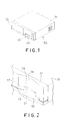
- FIG. 1 is a perspective view of an information recording and reproducing apparatus according to an embodiment of the present invention.
- FIG. 2 is a perspective view of part of a front panel of the information recording and reproducing apparatus of FIG. 1.
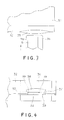
- FIG. 3 is a plan view of part of the front panel of FIG. 1, showing that an optical memory card is going to be inserted into the information recording and reproducing apparatus of FIG. 1.
- FIG. 4 is a front elevation of the front panel of FIG. 1.
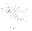
- FIG. 5 is an illustration of a state of inserting the optical memory card into a card receiving slot of the information recording and reproducing apparatus of FIG. 1.
- the rectangular information recording and reproducing apparatus which is mounted on a mounting surface 30 has a reduced thickness.
- the apparatus comprises a main casing 31 in the form of a box.
- the front portion of the main casing 31 has a front panel 32 mounted thereon.
- the opposite sidewalls of the main casing 31 have ventilating openings.
- the front panel 32 has a lying card receiving slot 33.
- the operator inserts an optical memory card 8 into the apparatus through the card receiving slot 33.
- the optical memory card 8 has a data storage region 9a and a guard region 9b.
- An optical head (not shown) within the main casing 31 can record and reproduce data into and out of the data storage region 9a, a card carriage (not shown) receiving the card 8 in the casing 31 transfers the card 8 between the card receiving slot 33 and the optical head.
- the front panel 32 has a card receiving plate 34 adjoining the lower edge of the card receiving slot 33.
- the card receiving plate 34 has a convex front edge projecting forward from the front panel 32.
- the upper surface 35, receiving and contacting the optical memory card 8, of the card receiving plate 34 is flat and flush with the bottom surface of the card receiving slot 33.
- the upper surface 35 extends forward from the lower edge of the card receiving slot 33 and is generally sector-shaped.
- the maximum length of the card receiving plate 34 is larger than the length of the card receiving slot 33.
- a portion of the front panel 32 extending upward from the upper edge of the card receiving slot 33 has a concave surface 36 in the inner cylindrical form.
- the concave surface 36 has a length equal to the maximum length of the card receiving plate 34.
- the side edges of the card receiving slot 33 have bevelled surfaces 37.
- the upper edge of the card receiving slot 33 has a bevelled surface 38.
- These bevelled surfaces 37 and 38 facilitate the operator to insert the optical memory card 8 into the card receiving slot 33. Therefore, a boundary between the concave surface 36 and the upper bevelled surface 38 forms the upper edge line of the card receiving slot 33. Since the concave surface 36 swells in a direction of the insertion of the optical memory card 8, the upper edge line of the card receiving slot 33 is convex upward.
- the upper and lower wall surfaces of the card receiving slot 33 have protrusions 39 contacting the guard regions 9b in the optical memory card 8 in order to protect the data storage region 9a in the optical memory card 8 from being fretted when the operator inserts the optical memory card 8 into the card receiving slot 33.
- the operator In operation, the operator, as shown in FIG. 5, approaches the optical memory card 8 from above the card receiving slot 33 down to the card receiving slot 33 in front of the front panel 32 on the apparatus mounted on the mounting surface 30. The operator then contacts the front end of the optical memory card 8 with the upper surface 35 of the card receiving plate 34. The operator then falls the optical memory card 8 in the direction of the arrow N and orients the optical memory card 8 along the axis of the card receiving slot 33.
- the operator can approache the optical memory card 8 from above the card receiving slot 33 down to the card receiving slot 33 in front of the front panel 32 and contacts the front end of the optical memory card 8 with the upper surface 35 of the card receiving plate 34.
Abstract
Description
Claims (2)
- An information recording and reproducing apparatus comprising a front panel (32) having a horizontally extending card receiving slot (33), an optical memory card (8) including a data storage region (9a) and capable of being inserted into the card receiving slot (33), an optical head (18) recording and reproducing data into and out of the data storage region (9a) of the optical memory card (8), and a card carriage (6) retaining the optical memory card (8) and transferring the optical memory card (8) between the card receiving slot (33) and the optical head (18), CHARACTERIZED IN THAT the lower edge of the card receiving slot (33) has a card receiver (34) adjoining thereof, an upper surface (35) of the card receiver (34) being flush with the lower edge surface of the card receiving slot (33), the card receiver (34) projecting forward from the front panel (32).
- The apparatus as recited in claim 1, CHARACTERIZED IN THAT the upper edge of the card receiving slot (33) has a concave surface (36).
Applications Claiming Priority (7)
| Application Number | Priority Date | Filing Date | Title |
|---|---|---|---|
| JP3836293 | 1993-02-26 | ||
| JP5038362A JP3056607B2 (en) | 1993-02-26 | 1993-02-26 | Information recording / reproducing device |
| JP38362/93 | 1993-02-26 | ||
| JP5134612A JP2986650B2 (en) | 1993-06-04 | 1993-06-04 | Information recording / reproducing device |
| JP13461293 | 1993-06-04 | ||
| JP134612/93 | 1993-06-04 | ||
| EP94102744A EP0613140B1 (en) | 1993-02-26 | 1994-02-24 | Information recording and reproducing apparatus |
Related Parent Applications (1)
| Application Number | Title | Priority Date | Filing Date |
|---|---|---|---|
| EP94102744A Division EP0613140B1 (en) | 1993-02-26 | 1994-02-24 | Information recording and reproducing apparatus |
Publications (2)
| Publication Number | Publication Date |
|---|---|
| EP0831485A1 true EP0831485A1 (en) | 1998-03-25 |
| EP0831485B1 EP0831485B1 (en) | 2002-04-10 |
Family
ID=26377603
Family Applications (2)
| Application Number | Title | Priority Date | Filing Date |
|---|---|---|---|
| EP94102744A Expired - Lifetime EP0613140B1 (en) | 1993-02-26 | 1994-02-24 | Information recording and reproducing apparatus |
| EP97119881A Expired - Lifetime EP0831485B1 (en) | 1993-02-26 | 1994-02-24 | Information recording and reproducing apparatus |
Family Applications Before (1)
| Application Number | Title | Priority Date | Filing Date |
|---|---|---|---|
| EP94102744A Expired - Lifetime EP0613140B1 (en) | 1993-02-26 | 1994-02-24 | Information recording and reproducing apparatus |
Country Status (8)
| Country | Link |
|---|---|
| US (2) | US5608699A (en) |
| EP (2) | EP0613140B1 (en) |
| KR (1) | KR100188900B1 (en) |
| CN (1) | CN1045836C (en) |
| AU (1) | AU665894B2 (en) |
| CA (1) | CA2116156C (en) |
| DE (2) | DE69420159T2 (en) |
| TW (2) | TW251365B (en) |
Families Citing this family (9)
| Publication number | Priority date | Publication date | Assignee | Title |
|---|---|---|---|---|
| US6938825B1 (en) * | 1989-04-24 | 2005-09-06 | Ultracard, Inc. | Data system |
| US6502755B2 (en) * | 1998-04-09 | 2003-01-07 | Dcard, Inc. | Optical data storage card |
| US7487908B1 (en) | 1999-10-23 | 2009-02-10 | Ultracard, Inc. | Article having an embedded accessible storage member, apparatus and method for using same |
| US8397998B1 (en) | 1999-10-23 | 2013-03-19 | Ultracard, Inc. | Data storage device, apparatus and method for using same |
| EP1154411A1 (en) * | 2000-05-09 | 2001-11-14 | I-Ming Chen | Data storage medium and apparatus for reading a data storage medium |
| AU2002214323A1 (en) * | 2000-11-17 | 2002-05-27 | Kabushiki Kaisha Sankyo Seiki Seisakusho | Foreign matter detecting mechanism, carriage moving mechanism and method for operating carriage moving mechanism |
| CN1319022C (en) * | 2001-04-12 | 2007-05-30 | 株式会社三协精机制作所 | Card ejecting mechanism |
| FR2855305A1 (en) * | 2003-05-22 | 2004-11-26 | Renault Sa | Disk drive for use in vehicle e.g. car, has horizontal slot for introducing disc within drive, and facade including guiding unit situated in lower end extension of slot to facilitate introduction of disc into slot |
| CN109742639B (en) * | 2019-03-07 | 2023-12-08 | 深圳市迅科达智能科技有限公司 | SIM card plug-in mechanism |
Citations (5)
| Publication number | Priority date | Publication date | Assignee | Title |
|---|---|---|---|---|
| DE1099201B (en) * | 1957-09-04 | 1961-02-09 | Telefunken Gmbh | Magnetic dictation device with foil-shaped recording medium and rotating support plate |
| US3706860A (en) * | 1970-08-20 | 1972-12-19 | Wiltek Inc | Magnetic card data recorder/reproducer |
| US4048476A (en) * | 1976-04-09 | 1977-09-13 | Ncr Corporation | Card reader |
| JPS6173260A (en) * | 1984-09-18 | 1986-04-15 | Matsushita Electric Ind Co Ltd | Magnetic card recorder and reproducing device |
| DE3034517C1 (en) * | 1980-09-12 | 1987-01-02 | Copytex-Abrechnungssysteme für Dienstleistungsautomaten GbmH, 7742 St Georgen | Device for transporting a data carrier in a data recognition device |
Family Cites Families (18)
| Publication number | Priority date | Publication date | Assignee | Title |
|---|---|---|---|---|
| DE1099101B (en) * | 1959-03-21 | 1961-02-09 | Siemens Ag | Control and shutdown element for nuclear reactors |
| US3766687A (en) * | 1972-02-16 | 1973-10-23 | Docutel Corp | Apparatus for entry control |
| US3959623A (en) * | 1973-03-08 | 1976-05-25 | Kabushiki Kaisha Sankyo Seiki Seisakusho | Card cassette |
| US3909595A (en) * | 1974-08-08 | 1975-09-30 | Diebold Inc | Entry gate construction for credit card actuated automatic remote banking equipment |
| US4236667A (en) * | 1979-07-20 | 1980-12-02 | Amp Incorporated | Low insertion force card reader |
| JP2542359B2 (en) * | 1985-05-22 | 1996-10-09 | キヤノン株式会社 | Information recording / reproducing device |
| JPS62132264A (en) * | 1985-12-05 | 1987-06-15 | Toshiba Corp | Conveyance maintaining mechanism of optical type card |
| US4916687A (en) * | 1986-05-13 | 1990-04-10 | Canon Kabushiki Kaisha | Apparatus for mounting and rotating an optical card for recording and/or reproducing information |
| JP2754530B2 (en) * | 1986-07-25 | 1998-05-20 | オムロン株式会社 | Card processing equipment |
| US4837814A (en) * | 1986-09-29 | 1989-06-06 | Anritsu Corporation | Telephone set |
| JPS63200291A (en) * | 1987-02-16 | 1988-08-18 | Toshiba Corp | Medium processor |
| EP0296590B1 (en) * | 1987-06-23 | 1993-10-27 | Omron Tateisi Electronics Co. | Optical card processing apparatus |
| JPH01118275A (en) * | 1987-10-31 | 1989-05-10 | Toshiba Corp | Optical head driving device |
| AT394462B (en) * | 1990-06-01 | 1992-04-10 | Philips Nv | SCANNER DEVICE FOR A CHIP CARD |
| JPH0486292U (en) * | 1990-11-22 | 1992-07-27 | ||
| JP3311362B2 (en) * | 1991-04-10 | 2002-08-05 | 株式会社日本コンラックス | Information recording / reproducing device |
| US5434404A (en) * | 1991-10-11 | 1995-07-18 | Verifone, Inc. | Linear scanner apparatus for communicating with a data card |
| AU5538494A (en) * | 1992-10-30 | 1994-05-24 | Microbilt Corporation | Multi-reader transaction terminal |
-
1994
- 1994-02-21 TW TW083101441A patent/TW251365B/zh active
- 1994-02-21 TW TW084101475A patent/TW257860B/zh active
- 1994-02-22 CA CA002116156A patent/CA2116156C/en not_active Expired - Fee Related
- 1994-02-23 US US08/200,740 patent/US5608699A/en not_active Expired - Fee Related
- 1994-02-24 EP EP94102744A patent/EP0613140B1/en not_active Expired - Lifetime
- 1994-02-24 AU AU56376/94A patent/AU665894B2/en not_active Ceased
- 1994-02-24 KR KR1019940003265A patent/KR100188900B1/en not_active IP Right Cessation
- 1994-02-24 DE DE69420159T patent/DE69420159T2/en not_active Expired - Fee Related
- 1994-02-24 DE DE69430392T patent/DE69430392T2/en not_active Expired - Fee Related
- 1994-02-24 EP EP97119881A patent/EP0831485B1/en not_active Expired - Lifetime
- 1994-02-26 CN CN94104079A patent/CN1045836C/en not_active Expired - Fee Related
-
1996
- 1996-11-06 US US08/743,706 patent/US5801368A/en not_active Expired - Fee Related
Patent Citations (5)
| Publication number | Priority date | Publication date | Assignee | Title |
|---|---|---|---|---|
| DE1099201B (en) * | 1957-09-04 | 1961-02-09 | Telefunken Gmbh | Magnetic dictation device with foil-shaped recording medium and rotating support plate |
| US3706860A (en) * | 1970-08-20 | 1972-12-19 | Wiltek Inc | Magnetic card data recorder/reproducer |
| US4048476A (en) * | 1976-04-09 | 1977-09-13 | Ncr Corporation | Card reader |
| DE3034517C1 (en) * | 1980-09-12 | 1987-01-02 | Copytex-Abrechnungssysteme für Dienstleistungsautomaten GbmH, 7742 St Georgen | Device for transporting a data carrier in a data recognition device |
| JPS6173260A (en) * | 1984-09-18 | 1986-04-15 | Matsushita Electric Ind Co Ltd | Magnetic card recorder and reproducing device |
Non-Patent Citations (1)
| Title |
|---|
| PATENT ABSTRACTS OF JAPAN vol. 10, no. 243 (P - 489) 21 August 1986 (1986-08-21) * |
Also Published As
| Publication number | Publication date |
|---|---|
| CN1045836C (en) | 1999-10-20 |
| EP0613140B1 (en) | 1999-08-25 |
| DE69430392D1 (en) | 2002-05-16 |
| US5801368A (en) | 1998-09-01 |
| DE69420159T2 (en) | 1999-12-09 |
| CA2116156A1 (en) | 1994-08-27 |
| EP0613140A3 (en) | 1995-03-01 |
| DE69420159D1 (en) | 1999-09-30 |
| AU5637694A (en) | 1994-09-15 |
| TW251365B (en) | 1995-07-11 |
| EP0831485B1 (en) | 2002-04-10 |
| CA2116156C (en) | 1996-09-10 |
| US5608699A (en) | 1997-03-04 |
| CN1101743A (en) | 1995-04-19 |
| EP0613140A2 (en) | 1994-08-31 |
| KR100188900B1 (en) | 1999-06-01 |
| DE69430392T2 (en) | 2003-01-09 |
| TW257860B (en) | 1995-09-21 |
| AU665894B2 (en) | 1996-01-18 |
Similar Documents
| Publication | Publication Date | Title |
|---|---|---|
| US6109939A (en) | Memory card and receptacle for same | |
| US4805770A (en) | Cassette with tray ejection means | |
| US5588850A (en) | Grounding means for memory card connector | |
| US7673805B2 (en) | Mini card adapter | |
| EP0739011B1 (en) | Keying slots on cartridge | |
| EP1150298A1 (en) | Case for encasing disc cartridge therein | |
| EP0831485A1 (en) | Information recording and reproducing apparatus | |
| EP0774727B1 (en) | IC Card reading/writing device | |
| JP3117393B2 (en) | Storage media storage box | |
| EP0660457B1 (en) | Electric connector | |
| US5937359A (en) | Apparatus which includes a removable casing that contains an adapter for reading chip cards of different formats | |
| EP0896289A3 (en) | Card connector | |
| JP2550294B2 (en) | Holder for data carrier | |
| US5454633A (en) | Disk storage box | |
| EP0920010B1 (en) | Magnetic disk cartridge | |
| JP4347018B2 (en) | Memory card compatible device and memory card module | |
| US6004143A (en) | Mounting structure of I/O connector in magnetic disk drive | |
| CN219591358U (en) | Information assembly and wafer box | |
| CN116544142B (en) | Information assembly and wafer box | |
| CN212867179U (en) | Computer key storage device and key management machine | |
| JPH05116828A (en) | Tray mounting structure to main body | |
| GB2083679A (en) | Disc record player | |
| US7337449B2 (en) | Disk drive for minimizing jamming during disk positioning | |
| KR200156038Y1 (en) | Cassette tape error insert prevention apparatus of video cassette recorder | |
| JPH054159Y2 (en) |
Legal Events
| Date | Code | Title | Description |
|---|---|---|---|
| PUAI | Public reference made under article 153(3) epc to a published international application that has entered the european phase |
Free format text: ORIGINAL CODE: 0009012 |
|
| AC | Divisional application: reference to earlier application |
Ref document number: 613140 Country of ref document: EP |
|
| AK | Designated contracting states |
Kind code of ref document: A1 Designated state(s): CH DE FR GB IT LI NL SE |
|
| 17P | Request for examination filed |
Effective date: 19980326 |
|
| 17Q | First examination report despatched |
Effective date: 19990217 |
|
| GRAG | Despatch of communication of intention to grant |
Free format text: ORIGINAL CODE: EPIDOS AGRA |
|
| GRAG | Despatch of communication of intention to grant |
Free format text: ORIGINAL CODE: EPIDOS AGRA |
|
| GRAH | Despatch of communication of intention to grant a patent |
Free format text: ORIGINAL CODE: EPIDOS IGRA |
|
| GRAH | Despatch of communication of intention to grant a patent |
Free format text: ORIGINAL CODE: EPIDOS IGRA |
|
| REG | Reference to a national code |
Ref country code: GB Ref legal event code: IF02 |
|
| GRAA | (expected) grant |
Free format text: ORIGINAL CODE: 0009210 |
|
| AC | Divisional application: reference to earlier application |
Ref document number: 613140 Country of ref document: EP |
|
| AK | Designated contracting states |
Kind code of ref document: B1 Designated state(s): CH DE FR GB IT LI NL SE |
|
| PG25 | Lapsed in a contracting state [announced via postgrant information from national office to epo] |
Ref country code: NL Free format text: LAPSE BECAUSE OF FAILURE TO SUBMIT A TRANSLATION OF THE DESCRIPTION OR TO PAY THE FEE WITHIN THE PRESCRIBED TIME-LIMIT Effective date: 20020410 Ref country code: LI Free format text: LAPSE BECAUSE OF FAILURE TO SUBMIT A TRANSLATION OF THE DESCRIPTION OR TO PAY THE FEE WITHIN THE PRESCRIBED TIME-LIMIT Effective date: 20020410 Ref country code: FR Free format text: LAPSE BECAUSE OF FAILURE TO SUBMIT A TRANSLATION OF THE DESCRIPTION OR TO PAY THE FEE WITHIN THE PRESCRIBED TIME-LIMIT Effective date: 20020410 Ref country code: CH Free format text: LAPSE BECAUSE OF FAILURE TO SUBMIT A TRANSLATION OF THE DESCRIPTION OR TO PAY THE FEE WITHIN THE PRESCRIBED TIME-LIMIT Effective date: 20020410 |
|
| REG | Reference to a national code |
Ref country code: CH Ref legal event code: EP |
|
| REF | Corresponds to: |
Ref document number: 69430392 Country of ref document: DE Date of ref document: 20020516 |
|
| PG25 | Lapsed in a contracting state [announced via postgrant information from national office to epo] |
Ref country code: SE Free format text: LAPSE BECAUSE OF FAILURE TO SUBMIT A TRANSLATION OF THE DESCRIPTION OR TO PAY THE FEE WITHIN THE PRESCRIBED TIME-LIMIT Effective date: 20020710 |
|
| NLV1 | Nl: lapsed or annulled due to failure to fulfill the requirements of art. 29p and 29m of the patents act | ||
| REG | Reference to a national code |
Ref country code: CH Ref legal event code: PL |
|
| EN | Fr: translation not filed | ||
| PLBE | No opposition filed within time limit |
Free format text: ORIGINAL CODE: 0009261 |
|
| STAA | Information on the status of an ep patent application or granted ep patent |
Free format text: STATUS: NO OPPOSITION FILED WITHIN TIME LIMIT |
|
| 26N | No opposition filed |
Effective date: 20030113 |
|
| PGFP | Annual fee paid to national office [announced via postgrant information from national office to epo] |
Ref country code: GB Payment date: 20050223 Year of fee payment: 12 |
|
| PGFP | Annual fee paid to national office [announced via postgrant information from national office to epo] |
Ref country code: DE Payment date: 20050425 Year of fee payment: 12 |
|
| PG25 | Lapsed in a contracting state [announced via postgrant information from national office to epo] |
Ref country code: GB Free format text: LAPSE BECAUSE OF NON-PAYMENT OF DUE FEES Effective date: 20060224 |
|
| PGFP | Annual fee paid to national office [announced via postgrant information from national office to epo] |
Ref country code: IT Payment date: 20060228 Year of fee payment: 13 |
|
| PG25 | Lapsed in a contracting state [announced via postgrant information from national office to epo] |
Ref country code: DE Free format text: LAPSE BECAUSE OF NON-PAYMENT OF DUE FEES Effective date: 20060901 |
|
| GBPC | Gb: european patent ceased through non-payment of renewal fee |
Effective date: 20060224 |
|
| PG25 | Lapsed in a contracting state [announced via postgrant information from national office to epo] |
Ref country code: IT Free format text: LAPSE BECAUSE OF NON-PAYMENT OF DUE FEES Effective date: 20070224 |