EP0831443B1 - Sensor for an electric circuit - Google Patents
Sensor for an electric circuit Download PDFInfo
- Publication number
- EP0831443B1 EP0831443B1 EP97810698A EP97810698A EP0831443B1 EP 0831443 B1 EP0831443 B1 EP 0831443B1 EP 97810698 A EP97810698 A EP 97810698A EP 97810698 A EP97810698 A EP 97810698A EP 0831443 B1 EP0831443 B1 EP 0831443B1
- Authority
- EP
- European Patent Office
- Prior art keywords
- oscillation
- plate
- mat
- transmitter according
- sensor
- Prior art date
- Legal status (The legal status is an assumption and is not a legal conclusion. Google has not performed a legal analysis and makes no representation as to the accuracy of the status listed.)
- Expired - Lifetime
Links
Images
Classifications
-
- G—PHYSICS
- G08—SIGNALLING
- G08B—SIGNALLING OR CALLING SYSTEMS; ORDER TELEGRAPHS; ALARM SYSTEMS
- G08B13/00—Burglar, theft or intruder alarms
- G08B13/02—Mechanical actuation
- G08B13/10—Mechanical actuation by pressure on floors, floor coverings, stair treads, counters, or tills
-
- F—MECHANICAL ENGINEERING; LIGHTING; HEATING; WEAPONS; BLASTING
- F16—ENGINEERING ELEMENTS AND UNITS; GENERAL MEASURES FOR PRODUCING AND MAINTAINING EFFECTIVE FUNCTIONING OF MACHINES OR INSTALLATIONS; THERMAL INSULATION IN GENERAL
- F16P—SAFETY DEVICES IN GENERAL; SAFETY DEVICES FOR PRESSES
- F16P3/00—Safety devices acting in conjunction with the control or operation of a machine; Control arrangements requiring the simultaneous use of two or more parts of the body
- F16P3/12—Safety devices acting in conjunction with the control or operation of a machine; Control arrangements requiring the simultaneous use of two or more parts of the body with means, e.g. feelers, which in case of the presence of a body part of a person in or near the danger zone influence the control or operation of the machine
-
- H—ELECTRICITY
- H01—ELECTRIC ELEMENTS
- H01H—ELECTRIC SWITCHES; RELAYS; SELECTORS; EMERGENCY PROTECTIVE DEVICES
- H01H3/00—Mechanisms for operating contacts
- H01H3/02—Operating parts, i.e. for operating driving mechanism by a mechanical force external to the switch
- H01H3/14—Operating parts, i.e. for operating driving mechanism by a mechanical force external to the switch adapted for operation by a part of the human body other than the hand, e.g. by foot
- H01H3/141—Cushion or mat switches
Definitions
- the invention relates to a sensor for a Switchgear according to the preamble of Claim 1.
- the invention relates to a transmitter, designed as a contact mat together with a switching device a security system, for example forms in the form of an area security.
- Security systems of this type are used for active and passive securing of objects, for example Machines such as industrial robot cells, wood and Metalworking machines etc.
- An encoder switch
- switch electrically connected Contact mat
- a switching device that together form an electrical circuit. Its mode of operation is that under load the contact mat closes a switch and the Circuit is closed.
- the now flowing Current is transferred from the switching device into a functional instruction, for example in a shutdown command one connected to the switching device mechanical or other equipment such as barriers etc., implemented.
- Switchgear are known to a high degree technical level and have themselves in their currently predominant embodiments proven accordingly.
- British Patent application GB 2261 115A is a security system in a predominantly known version described.
- the switching device shown there includes a pressure-sensitive contact mat, the to form an electrical circuit with a switchgear is connectable.
- a contact mat With the known Contact mat is the same as in the case of Invention for a so-called hollow contact mat, so a contact mat, the walls of which Enclose closed cavity (hollow contact mats hereinafter also called mats), in which according to British patent application called an electrical Switch comprising two switching elements is recorded.
- the Integrity of the mat can be achieved, for example Damage (tearing, perforation, etc.) to one or several wall parts through the cavity such an entry of foreign substances (Water, paint, etc.) are affected, whereby especially the latter the functionality of the Cancel or lower the switch.
- Damage tearing, perforation, etc.
- foreign substances Water, paint, etc.
- These two known mats therefore necessarily to be made Reviews, the results of which for one certain forward-looking period Should stand up as such for predetermined, ordinary, i.e. usually occurring load conditions proven, not however for the unexpected extraordinary Load conditions.
- the latter an example would be Driving over a mat with an overweight Vehicle - could use a mat shortly after damage proper function check, without this damage until the next exam date would be noticed, a condition leading to sudden or gradually occurring inoperability the mat can lead.
- a mat line i.e. Signal generator line
- This Type of electrical monitoring sets electrical Facilities ahead, which in turn periodically are to be checked for their functionality.
- a mat should also be a static safety exhibit.
- static safety one Mat is understood the ability of a mat when commissioning one that includes them Security system to detect if they are under load stands or not to send appropriate signals to a Switchgear. This ability is for the Security of people or objects Commissioning a protected system is important because the only way for the system to recognize whether a Person or thing is on the mat, i.e. the Mat is under load to this load condition to switch accordingly.
- the object of the invention is a To create matte simple structure that itself through static safety and ability distinguished, even their functionality permanently monitor, and the task is conveyed of the characterizing features of claim 1 solved.
- the invention comes as an active switch or switching element (hereinafter jointly switch called), recorded in the cavity of the mat, a excitable vibrating body for use, which leads to vibrations certain frequencies and amplitudes are excited, taking changes in these vibration parameters for example as a result of damping, as Switch signals are used.
- a switching signal Will be undamaged Mat with something in its cavity Vibrating bodies are loaded with a load, so the Dampened vibrations and the associated Parameter changes trigger a switching signal.
- the Mat designed according to the invention also fulfills the requirement of static security as it not just because of a change in Vibration parameters through damping under load triggers a shift, but as a result a damping process also detects whether something is on you stand if a security system including them is put into operation.
- the inventive Mat met with simple mechanical means and the principle of action of Utilization of vibration parameter changes your intended switching function with static Security, the mat using the same principle of action for constant self-monitoring of your Functionality applies.
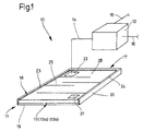
- Figure 1 shows a sensor 11 and one with the sensor 11 cooperating switching device 12 that together form a security system 10.
- the switching device 12 is not part of the invention, it is known to have the task of signals 11 coming from the encoder downstream in commands for switching Convert facilities.
- the switching device 12 when changing the vibration parameters as Manipulated variable or signal are evaluated the switching device 12 a redundant electronic Circuit that changes, for example Vibration amplitudes of a signal generator 13 evaluates and for the formulation and execution of Passes switching commands.
- the active connection between encoder 11 or the one included in it Signal generator 13 is through the connecting line 14 indicated schematically. With electrical input 15 and output 16 is indicated that the switching device 12 without the encoder 11 an electrical Circuit for switching downstream devices (not shown) forms, the encoder 11 from the switching device 12 the necessary signal Receives vibration generation.
- the sensor 11 comprises a casing 17 with a cavity 18 spaced from two Cover surfaces 19 (a cover surface 19 is not shown), spaced from one Circumference of the cover surface 19 surrounding wall 20 is formed.
- Cover surfaces 19 and wall 20 consist of an elastic material, preferably a plastic.
- Top surfaces and walls have a thickness of 3 to 10 mm, preferably 3 up to 5 mm. Envelopes 17 with this wall dimensioning are characterized by good service life and make a decisive contribution to the Requirement that an encoder 11, i.e. a mat 11 according to the invention a total thickness of less than Should have 10 mm, this for the sake of Functional reliability and the comfort of being run over.
- the dimensioning between Dimensions of the cavity 18 and that of the signal generator 13 is such that the signal generator 13 in the cavity 18, possibly including compressible filling material movements intended for it can perform.
- Signal generator 13 as a vibrating body 13a after a development of the invention preferably as a plate 13b is formed. As from Fig. 1 can be seen, the plate 13b with a vibration exciter (Actuator) 21 and a vibration sensor (Sensor) 22 provided.
- actuator 21 and sensor 22 in one certain distance (actuator 21 at the beginning and sensor at End of an oscillation path) to each other, for example on a two corners of the plate 13b connecting Line to arrange.
- Actuator 21 at the beginning and sensor 22 at the end of one Provide vibrating body.
- actuator 21 and sensor 22 Representation and measurement of vibrations of the plate 13b and by damping (triggered by entering or driving on the mat 11) caused changes the most reproducible vibration parameter by the sensor 22.
- Very good, i.e. uniform excitation of the plate 13b and recording the changes in vibration in the event of stress are achieved according to the invention if the Plate 13b (i.e.
- the plate 13b is idealized as one beams placed in a plane (vibrating beam).
- the bar is connected at one end, preferably mechanically connected sections, i.e. plate strip 26 divided, the one so divided Bars (the sections lie side by side) continuous vibration in operative connection stand so that a so-called vibration path with a beginning and an end.
- the plate 13b has an actuator 21 on the piezoelectric Principle based element has been shown to be advantageous, that on the plate 13b like the sensor 22 can be glued on.
- the peripheral wall 20 including yours Connection with the cover surfaces 19 let the Cover surfaces 19 outside "dead zone" in shape of a circumferential stripe arise within a mat 11 does not respond to loads.
- These dead zones increase (i.e. the stripes become wider) when mats 11 are strung together the dead zone problem in particular becomes acute in places where, for example the corners of four mats 11 meet. According to the invention, these dead zones are in their Counteracted effects when the adjacent peripheral walls 20 compressible material are formed.
- a mat 11 designed according to the invention shows the intended mode of operation in constant, reliable form even when the plate 13b at least three adjacent plate strips 26 and has vibration exciters 21 and Vibration sensor 22 on the free-swinging, a plate corner enclosing each other diagonally opposite ends of the plate strips 26 are arranged. Because of this execution can the actuator 21 the strip on which it is located, to stimulate vibrations, these overlap a second streak and will be at the end of the third strip recorded by the sensor 22 and checked with regard to their vibration parameters. Are the vibration parameters on sensor 22 in same orders of magnitude as starting from the actuator 21, then there is no damping of the vibrations, translated into the function of the mat this means the mat 11 is unloaded, the cavity is intact, i.e.
- the actuator 21 is useful for the invention outgoing signal, i.e. as an excitation signal Natural vibration of the plate 13b, i.e. as one after the invention guided vibration, which in a Level bars or their side by side Sections over their respective connections to be used sequentially, because that's a good transfer ratio is achieved.
- the security increases, if you excite a certain frequency and only this frequency is used for evaluation.
Abstract
Description
Die Erfindung betrifft einen Geber für ein Schaltgerät nach dem Oberbegriff des Patentanspruches 1.The invention relates to a sensor for a Switchgear according to the preamble of Claim 1.
Insbesondere betrifft die Erfindung einen Geber, ausgebildet als Kontaktmatte, die zusammen mit einem Schaltgerät ein Sicherheitssystem, beispielsweise in Form einer Flächensicherung bildet. Sicherheitssysteme dieser Art dienen der aktiven und passiven Sicherung von Gegenständen, beispielsweise Maschinen, wie Industrieroboterzellen, Holzund Metallbearbeitungsmaschinen etc. Bei Eintritt beispielsweise in den Funktionsbereich einer in Betrieb stehenden Industrieroboterzelle können Personen und Gegenstände ebenso zu Schaden kommen wie auch die Industrieroboterzelle als hochwertiges Wirtschaftsgut. Ein Sicherheitssystem besteht im wesentlichen aus einem Geber (Schalter) in Form einer oder mehrerer elektrisch miteinander verbundener Kontaktmatte(n) und einem Schaltgerät, die zusammen einen elektrischen Stromkreis bilden. Seine Funktionsweise ist die, dass bei Belastung der Kontaktmatte ein Schalter schliesst und der Stromkreis geschlossen wird. Der jetzt fliessende Strom wird vom Schaltgerät in eine Funktionsanweisung, beispielsweise in einen Abschaltbefehl an eine mit dem Schaltgerät in Verbindung stehende maschinelle oder sonstige Einrichtung wie Abschrankungen etc., umgesetzt.In particular, the invention relates to a transmitter, designed as a contact mat together with a switching device a security system, for example forms in the form of an area security. Security systems of this type are used for active and passive securing of objects, for example Machines such as industrial robot cells, wood and Metalworking machines etc. Upon entry for example in the functional area of a Operating industrial robot cell can People and objects are also damaged as well as the industrial robot cell as a high-quality one Asset. A security system consists of essentially from an encoder (switch) in the form one or more electrically connected Contact mat (s) and a switching device that together form an electrical circuit. Its mode of operation is that under load the contact mat closes a switch and the Circuit is closed. The now flowing Current is transferred from the switching device into a functional instruction, for example in a shutdown command one connected to the switching device mechanical or other equipment such as barriers etc., implemented.
Sicherheitssysteme (folgend auch Schalteinrichtungen genannt) sind bekannt, auf einen hohen technischen Entwicklungsstand gebracht und haben sich in ihren derzeit vorherrschenden Ausführungsformen entsprechend bewährt. In der britischen Patentanmeldung GB 2261 115A ist ein Sicherheitssystem in vorherrschend bekannter Ausführung beschrieben. Die dort gezeigte Schalteinrichtung umfasst eine auf Druck ansprechende Kontaktmatte, die zur Bildung eines elektrischen Stromkreises mit einem Schaltgerät verbindbar ist. Bei der bekannten Kontaktmatte handelt es sich wie auch im Falle der Erfindung um eine sogenannte Hohlkontaktmatte, also um eine Kontaktmatte, deren Wandungen einen geschlossenen Hohlraum umschliessen (Hohlkontaktmatten folgend auch Matten genannt), in dem gemäss genannter britischen Patentanmeldung ein elektrischer Schalter, umfassend zwei Schaltelemente, aufgenommen ist. Wird die bekannte Matte belastet, gelangen die Schaltelemente zur gegenseitigen Anlage, wobei bei Entlastung elektrisch nicht leitende Federn die Schaltelemente in ihre beabstandete Ausgangslage zurückführen. Die Matte nach der genannten britischen Druckschrift lässt augenfällig werden, dass für eine zuverlässige Funktionsweise der Matte, insbesondere des Schalters in der Matte die Integrität der Matte (Unversehrtheit ihrer Wandungsteile) und des Hohlraumes (Freiheit von schalterfunktionsfremden Einschlüssen im Hohlraum) von entscheidender Bedeutung sind. Integrität der Matte, des Hohlraumes und der Funktionsfähigkeit des Schalters müssen insbesondere bei rauhem industriellen Dauereinsatz von Matten Gegenstand von Überprüfungen sein, wenn man plötzliche Funktionsunfähigkeit von Matten mit den daraus fliessenden Folgen vermeiden will. Die Integrität der Matte kann beispielsweise durch Beschädigung (Reissen, Perforation etc.) einer oder mehrerer Wandungsteile, die des Hohlraumes durch einen so ermöglichten Eintritt von Fremdstoffen (Wasser, Farben etc.) beeinträchtigt werden, wobei insbesondere letztere die Funktionsfähigkeit des Schalters aufheben oder herabsetzen. Diese bei den bekannten Matten mithin notwendigerweise vorzunehmenden Überprüfungen, deren Ergebnisse für einen bestimmten in die Zukunft gerichteten Zeitraum Bestand haben sollten, haben sich als solche für vorbestimmte, gewöhnliche, d.h. normalerweise auftretende Belastungszustände bewährt, nicht jedoch für unerwartete aussergewöhnliche Belastungszustände. Letztere - ein Beispiel wäre Überfahren einer Matte mit einem überschweren Fahrzeug - könnten eine Matte kurz nach deren ordnungsgemässen Funktionsüberprüfung beschädigen, ohne dass diese Schäden bis zum nächsten Prüfungstermin bemerkt würden, ein Zustand, der zur plötzlichen oder allmählich eintretenden Funktionsunfähigkeit der Matte führen kann. Gegen diese Gefährdung eines Sicherheitssystems ist es bekannt, in einer letzten Matte einer Mattenlinie (d.h. Signalgeberlinie) einen definierten elektrischen Widerstand vorzusehen, der es erlaubt, die Zustände der Matten, d.h. ihre Funktionsfähigkeit nicht periodisch sondern permanent zu überwachen. Diese Art der elektrischen Überwachung setzt elektrische Einrichtungen voraus, die ihrerseits wieder periodisch auf ihre Funktionsfähigkeit zu prüfen sind. Neben der funktionalen Sicherheit (Schaltsicherheit) sollte eine Matte auch eine statische Sicherheit aufweisen. Unter statischer Sicherheit einer Matte wird die Fähigkeit einer Matte verstanden, bei Inbetriebsetzung eines sie einschliessenden Sicherheitssystems zu erkennen, ob sie unter Last steht oder nicht, um entsprechende Signale an ein Schaltgerät zu senden. Diese Fähigkeit ist für die Sicherheit von Personen oder Gegenständen bei Inbetriebnahme eines geschützten Systems wichtig, da nur so für das System erkennbar wird, ob sich eine Person oder Sache auf der Matte befindet, d.h. die Matte unter Last steht, um diesem Lastzustand entsprechend zu schalten.Safety systems (hereinafter also switchgear are known to a high degree technical level and have themselves in their currently predominant embodiments proven accordingly. In the British Patent application GB 2261 115A is a security system in a predominantly known version described. The switching device shown there includes a pressure-sensitive contact mat, the to form an electrical circuit with a switchgear is connectable. With the known Contact mat is the same as in the case of Invention for a so-called hollow contact mat, so a contact mat, the walls of which Enclose closed cavity (hollow contact mats hereinafter also called mats), in which according to British patent application called an electrical Switch comprising two switching elements is recorded. If the known mat is loaded, the switching elements reach each other System, but not electrically when relieved conductive springs the switching elements in their return spaced starting position. The mat according to the British publication mentioned be striking that for a reliable How the mat works, especially the Switch in the mat the integrity of the mat (Integrity of its wall parts) and the Cavity (freedom from non-switch functions Inclusions in the cavity) are. Integrity of the mat, the cavity and the functionality of the switch must in particular with rough industrial continuous use of Mats should be the subject of reviews if one sudden inoperability of mats with the wants to avoid the consequences flowing from it. The Integrity of the mat can be achieved, for example Damage (tearing, perforation, etc.) to one or several wall parts through the cavity such an entry of foreign substances (Water, paint, etc.) are affected, whereby especially the latter the functionality of the Cancel or lower the switch. These two known mats therefore necessarily to be made Reviews, the results of which for one certain forward-looking period Should stand up as such for predetermined, ordinary, i.e. usually occurring load conditions proven, not however for the unexpected extraordinary Load conditions. The latter - an example would be Driving over a mat with an overweight Vehicle - could use a mat shortly after damage proper function check, without this damage until the next exam date would be noticed, a condition leading to sudden or gradually occurring inoperability the mat can lead. Against this Endangering a security system it is known in a last mat of a mat line (i.e. Signal generator line) a defined electrical Provide resistance that allows the states the mats, i.e. their functionality does not to be monitored periodically but continuously. This Type of electrical monitoring sets electrical Facilities ahead, which in turn periodically are to be checked for their functionality. In addition to functional safety (switching reliability) a mat should also be a static safety exhibit. Under static safety one Mat is understood the ability of a mat when commissioning one that includes them Security system to detect if they are under load stands or not to send appropriate signals to a Switchgear. This ability is for the Security of people or objects Commissioning a protected system is important because the only way for the system to recognize whether a Person or thing is on the mat, i.e. the Mat is under load to this load condition to switch accordingly.
Hiervon ausgehend ist Aufgabe der Erfindung, eine Matte einfachen Aufbaues zu schaffen, die sich durch statische Sicherheit und die Fähigkeit auszeichnet, selbst ihre Funktionsfähigkeit permanent zu überwachen, und die Aufgabe wird vermittels der kennzeichnenden Merkmale des Patentanspruches 1 gelöst.Proceeding from this, the object of the invention is a To create matte simple structure that itself through static safety and ability distinguished, even their functionality permanently monitor, and the task is conveyed of the characterizing features of claim 1 solved.
Die erfindungsgemässe Lehre verlässt den Stand der Technik, der sich bei Matten durch passive Schalter bzw. Schaltelemente kennzeichnet, indem sie letzere durch aktive Schaltelemente ersetzt. Unter passiven Schaltern bzw. Schaltelementen werden hier solche verstanden, bei denen Bewegungen für eine Schaltfunktion ausgelöst werden müssen, während erfindungsgemäss aktive Schalter in ständiger Bewegung gehalten sind und Schaltfunktion durch Änderungen eines Bewegungszustandes auslösen.The teaching according to the invention leaves the state of the Technology that works with mats through passive switches or switching elements characterized by the latter replaced by active switching elements. Under passive Switches or switching elements become such here understood where movements for a switching function must be triggered while according to the invention active switches in constant motion are held and switching function by changes trigger a state of motion.
Gemäss der Erfindung kommt als aktiver Schalter bzw. Schaltelement (folgend gemeinsam Schalter genannt), im Hohlraum der Matte aufgenommen, ein anregbarer Schwingkörper zur Anwendung, der zu Schwingungen bestimmter Frequenzen und Amplituden angeregt wird, wobei Änderungen dieser Schwingungsparameter beispielsweise als Folge von Dämpfungen, als Schaltsignale benutzt werden. Wird eine unbeschädigte Matte mit in ihrem Hohlraum befindlichem Schwingkörper mit einer Last belegt, so werden die Schwingungen gedämpft und die damit einhergehenden Parameteränderungen lösen ein Schaltsignal aus. Ist eine unbelastete Mattehülle beschädigt und gelangen Fremdkörper in den Hohlraum und in Kontakt mit dem Schwingkörper, so löst der Kontakt des Schwingkörpers mit dem Fremdkörper eine Dämpfung des Schwingkörpers aus, wobei die Änderungen der Schwingungsparameter als Signal anzeigen, dass die Funktionsfähigkeit des Schwingkörpers und damit der Matte beeinträchtigt ist. Bei unbelasteter, intakter Mattenhülle und beschädigtem Schwingkörper, beispielsweise durch Überfahren mit einer Überlast, ändern sich die Schwingungsparameter, was gleichermassen zu einem Signal umgesetzt wird. Die erfindungsgemäss ausgebildete Matte nützt somit durch Dämpfung ausgelöste Änderungen der Schwingungsparameter zur Erzeugung eines Schaltsignales für das Sicherheitssystem und zur ständigen Selbstüberwachung seiner Funktionsfähigkeit. Die erfindungsgemäss ausgebildete Matte erfüllt auch die Forderung der statischen Sicherheit, da sie nicht nur aufgrund einer Änderung der Schwingungsparameter durch Dämpfung bei Belastung einen Schaltvorgang auslöst, sondern als Folge eines Dämpfungsvorganges auch erkennt, ob etwas auf ihr steht, wenn ein sie einschliessendes Sicherheitssystem in Betrieb genommen wird. Die erfindungsgemässe Matte erfüllt so mit einfachen mechanischen Mitteln und dem Wirkungsprinzip der Verwertung von Schwingungsparameter -Änderungen die ihr zugedachte Schaltfunktion bei statischer Sicherheit, wobei die Matte das gleiche Wirkungsprinzip für die ständige Selbstüberwachung ihrer Funktionsfähigkeit anwendet.According to the invention comes as an active switch or switching element (hereinafter jointly switch called), recorded in the cavity of the mat, a excitable vibrating body for use, which leads to vibrations certain frequencies and amplitudes are excited, taking changes in these vibration parameters for example as a result of damping, as Switch signals are used. Will be undamaged Mat with something in its cavity Vibrating bodies are loaded with a load, so the Dampened vibrations and the associated Parameter changes trigger a switching signal. is an unloaded mat cover damaged and get Foreign matter in the cavity and in contact with the Vibrating body, so the contact of the vibrating body releases with the foreign body damping the Vibrating body, the changes in the Vibration parameters as a signal indicate that the Functionality of the vibrating body and thus the Mat is affected. With unloaded, intact Mat cover and damaged vibrating body, for example by running over with an overload, the vibration parameters change, which is equally is converted into a signal. According to the invention trained mat is useful Damping triggered changes in the vibration parameters to generate a switching signal for the security system and for constant self-monitoring its functionality. The Mat designed according to the invention also fulfills the requirement of static security as it not just because of a change in Vibration parameters through damping under load triggers a shift, but as a result a damping process also detects whether something is on you stand if a security system including them is put into operation. The inventive Mat met with simple mechanical means and the principle of action of Utilization of vibration parameter changes your intended switching function with static Security, the mat using the same principle of action for constant self-monitoring of your Functionality applies.
Vorteilhafte Ausgestaltungen ergeben sich aus den Merkmalen der dem Patentanspruch 1 folgenden Patentansprüche.Advantageous configurations result from the Features of the following claim 1 Claims.
Weitere Vorteile, Merkmale und Einzelheiten der Erfindung ergeben sich aus der folgenden Beschreibung eines bevorzugten Ausführungsbeispieles und der Zeichnung, es zeigt
- Fig. 1
- in perspektivischer und schematischer Darstellung einen erfindungsgemässen Geber, der mit einem Schaltgerät zusammen wirkt.
- Fig. 1
- a perspective and schematic representation of an encoder according to the invention, which interacts with a switching device.
Figur 1 zeigt einen Geber 11 und ein mit dem Geber
11 zusammenwirkendes Schaltgerät 12, die zusammen
ein Sicherheitssystem 10 bilden. Das Schaltgerät 12
ist nicht Teil der Erfindung, es hat bekanntermassen
die Aufgabe, vom Geber 11 ausgehende Signale
in Befehle für die Schaltung nachgeordneter
Einrichtungen umzuwandeln. Im Falle der Erfindung,
bei der Änderungen der Schwingungsparameter als
Stellgrösse oder Signal ausgewertet werden, umfasst
das Schaltgerät 12 eine redundante elektronische
Schaltung, die beispielsweise Änderungen der
Schwingungsamplituden eines Signalbildners 13
auswertet und zur Formulierung und Ausführung von
Schaltbefehlen weitergibt. Die Wirkverbindung
zwischen Geber 11 bzw. dem in ihm aufgenommenen
Signalbildner 13 ist durch die Verbindungsleitung
14 schematisch angedeutet. Mit elektrischem Eingang
15 und Ausgang 16 ist angedeutet, dass das Schaltgerät
12 ohne den Geber 11 einen elektrischen
Stromkreis zur Schaltung nachgeordneter Einrichtungen
(nicht gezeigt) bildet, wobei der Geber 11
vom Schaltgerät 12 das notwendige Signal zur
Schwingungserzeugung erhält.Figure 1 shows a
Der erfindungsgemässe Geber 11 umfasst eine Hülle
17 mit einem Hohlraum 18, der von zwei beabstandeten
Deckflächen 19 (eine Deckfläche 19 ist nicht
gezeigt), beabstandet gehalten von einer, den
Umfang der Deckfläche 19 umlaufenden Wandung 20
gebildet ist. Deckflächen 19 und Wandung 20
bestehen aus einem elastischen Werkstoff, vorzugsweise
einem Kunststoff. Deckflächen und Wandungen
haben eine Stärke von 3 bis 10 mm, vorzugsweise 3
bis 5 mm. Hüllen 17 mit dieser Wandungsdimensionierung
kennzeichnen sich durch gute Standzeiten und
leisten damit einen entscheidenden Beitrag an die
Forderung, dass ein Geber 11, d.h. eine Matte 11
nach der Erfindung eine Gesamtdicke von weniger als
10 mm haben soll, dies aus Gründen der
Funktionszuverlässigkeit und des Überfahrkomforts.
In den Hohlraum 18 ist der Signalbildner 13, von
den miteinander verbundenen Deckflächen 19 und der
Wandung 20 allseits umschlossen, d.h. abgedichtet
eingebracht, wobei die Dimensionierung zwischen
Abmessungen des Hohlraumes 18 und den des Signalbildners
13 so bemessen ist, dass der Signalbildner
13 im Hohlraum 18 ggfs unter Einschluss von
komprimierbarem Füllmaterial ihm zugedachte Bewegungen
ausführen kann. Gemäss der Erfindung ist der
Signalbildner 13 als ein Schwingkörper 13a nach
einer Weiterbildung der Erfindung bevorzugt als
eine Platte 13b ausgebildet. Wie aus Fig. 1
ersichtlich, ist die Platte 13b mit einem Schwingungserreger
(Aktor) 21 und einem Schwingungsaufnehmer
(Sensor) 22 versehen. Bevorzugt nach der
Erfindung ist Aktor 21 und Sensor 22 in einer
gewissen Distanz (Aktor 21 am Anfang und Sensor am
Ende eines Schwingungspfades) zueinander, beispielsweise
auf einer zwei Ecken der Platte 13b verbindenden
Linie, anzuordnen. Grundsätzlich ist der
Aktor 21 am Anfang und der Sensor 22 am Ende eines
Schwingkörpers vorzusehen. Mit einer dieser Anordnungen
von Aktor 21 und Sensor 22 liessen sich
Darstellung und Messung von Schwingungen der Platte
13b und durch Dämpfung (ausgelöst durch Betreten
oder Befahren der Matte 11) verursachte Änderungen
der Schwingungsparameter am reproduzierbarsten
durch den Sensor 22 aufnehmen. Sehr gute, d.h.
gleichförmige Anregung der Platte 13b und Aufnahme
der Schwingungsveränderungen im Belastungsfall
werden gemäss der Erfindung erreicht, wenn die
Platte 13b (d.h. der Signalbildner) so ausgebildet
ist, dass geführte Schwingungen dank einer speziellen
Formgebung der Platte 13b möglich werden. Zu
diesem Zweck ist die Platte 13b idealisiert als ein
in eine Ebene gelegter Balken (Schwingbalken) ausgebildet.
Aus konstruktiven Gründen (Grösse, d.h.
flächige Abmessung der Platte) ist der Balken in
miteinander einends verbundene, vorzugsweise mechanisch
verbundene Teilstücke, d.h. Plattenstreifen
26 aufgeteilt, die bezüglich einer den so aufgeteilten
Balken (die Teilstücke liegen nebeneinander)
durchlaufenden Schwingung in Wirkverbindung
stehen, so dass so ein sogenannter Schwingungspfad
mit einem Anfang und Ende gebildet wird. Für eine
gleichförmige Schwingungsanregung der Platte 13b
hat sich als Aktor 21 ein auf dem piezoelektrischen
Prinzip beruhendes Element als vorteilhaft erwiesen,
das auf der Platte 13b wie der Sensor 22
aufgeklebt sein kann.The
Die umlaufende Wandung 20 einschliesslich ihrer
Verbindung mit den Deckflächen 19 lassen eine die
Deckflächen 19 aussen umlaufende "Totzone" in Form
eines umlaufenden Streifens entstehen, innerhalb
der eine Matte 11 auf Belastungen nicht anspricht.
Diese Totzonen vergrössern sich (d.h. die Streifen
werden breiter), wenn Matten 11 aneinandergereiht
werden, wobei die Totzonen-Problematik besonders
akut wird an den Stellen, an denen beispielsweise
die Ecken von vier Matten 11 zusammentreffen.
Diesen Totzonen wird erfindungsgemäss in ihren
Auswirkungen dadurch entgegengewirkt, wenn die
aneinander grenzenden umlaufenden Wandungen 20 aus
komprimierbarem Werkstoff ausgebildet sind.The
Eine erfindungsgemäss ausgebildete Matte 11 zeigt
die ihr zugedachte Funktionsweise in stetiger,
verlässlicher Form bereits dann, wenn die Platte
13b mindestens drei nebeneinanderliegende Plattenstreifen
26 aufweist und Schwingungserreger 21 und
Schwingungsaufnehmer 22 an den freischwingenden,
eine Plattenecke einschliessenden, einander diagonal
gegenüberliegenden Enden der Plattenstreifen 26
angeordnet sind. Aufgrund dieser Ausführung kann
der Aktor 21 den Streifen, auf dem er sich befindet,
zu Schwingungen anregen, diese setzen sich über
einen zweiten Streifen fort und werden am Ende des
dritten Streifens vom Sensor 22 aufgenommen und
bezüglich ihrer Schwingungsparameter überprüft.
Liegen die Schwingungsparameter am Sensor 22 in
gleichen Grössenordnungen wie ausgehend vom Aktor
21, dann liegt keine Dämpfung der Schwingungen vor,
in die Funktion der Matte übersetzt bedeutet dies,
die Matte 11 ist unbelastet, der Hohlraum ist
intakt, d.h. er enthält keine artfremden Einschlüsse
wie Wasser, Eis etc. und bei Einschalten
des Sicherheitssystems würde - durch ausgelöste
Dämpfung - die Matte 11 sofort anzeigen, ob sie
durch eine Person oder Sache belastet ist. Stimmen
die Parameter zwischen Aktor 21 und Sensor 22 nicht
überein, dann liegt bedingt durch Belastung der
Matte und / oder durch Vorhandensein von Fremdkörpern
eine Dämpfung vor, wobei die Differenz der
Parameter (z.B. Amplitude oder Frequenz oder beide)
als Basis für das Auslösen eines Schaltsignales
verwendet wird.A
Zweckmässig für die Erfindung ist als vom Aktor 21
ausgehendes Signal, d.h. als Anregungssignal eine
Eigenschwingung der Platte 13b, d.h. als eine nach
der Erfindung geführte Schwingung, den in einer
Ebene liegenden Balken bzw. dessen nebeneinanderliegenden
Teilstücke über deren jeweiligen Verbindungen
nacheinander durchlaufend zu verwenden,
weil damit ein gutes Übertragungsverhältnis
erreicht wird. Zusätzlich erhöht sich die Sicherheit,
wenn man eine bestimmte Frequenz anregt und
zur Auswertung auch nur diese Frequenz verwendet.The
Claims (6)
- A transmitter (11) for a switch (12) comprising a casing (17) of elastic material consisting of two top surfaces (19) spaced apart by a wall (20) running around the circumference of said top surfaces (19) and a signal generator (13) reactive upon pressure loads which is arranged between said top surfaces (19) and being responsive with at least one top surface (19) characterised thereby that the signal generator (13) is formed as promptable oscillator (13a).
- Transmitter according to claim 1, characterised thereby that the oscillator (13a) is formed as a plate (13b).
- Transmitter according to claim 2, characterised thereby that the plate (13b) consists of partial segments (26) forming an oscillation path, said partial segments (26) in alternating mode extending from two of said plate's (13b) opposite sides (23, 24) leaving a spacing between said sides (23, 24) and forming slots (25) of equal distance which slots (25) only partially extend over said partial segments (26) so that said partial segments (26) are in a side by side position and at one end altematingly connected.
- Transmitter according to claim 3, characterised thereby that slots (25) are provided so that the plate (13b) comprises at least three partial segments (26) and that an oscillation generator (21) is arranged upon a freely oscillating end of a first partial segment and that an oscillation pick-up (22) is arranged upon the freely oscillation end of a following partial segment (26.)
- Transmitter according to claim 4, characterised thereby that the oscillation generator (21) and the oscillation pick-up (22) are arranged upon the plate (13b) in a diagonally staggered position to each other.
- Transmitter according to one of the claims 1 to 5, characterised that the oscillation generator (21) is an element functioning according to the piezoelectrical action principle.
Applications Claiming Priority (2)
| Application Number | Priority Date | Filing Date | Title |
|---|---|---|---|
| DE19639207 | 1996-09-24 | ||
| DE19639207A DE19639207A1 (en) | 1996-09-24 | 1996-09-24 | Electrical circuit encoder |
Publications (3)
| Publication Number | Publication Date |
|---|---|
| EP0831443A2 EP0831443A2 (en) | 1998-03-25 |
| EP0831443A3 EP0831443A3 (en) | 1999-07-21 |
| EP0831443B1 true EP0831443B1 (en) | 2002-05-15 |
Family
ID=7806746
Family Applications (1)
| Application Number | Title | Priority Date | Filing Date |
|---|---|---|---|
| EP97810698A Expired - Lifetime EP0831443B1 (en) | 1996-09-24 | 1997-09-23 | Sensor for an electric circuit |
Country Status (6)
| Country | Link |
|---|---|
| EP (1) | EP0831443B1 (en) |
| AT (1) | ATE217722T1 (en) |
| DE (2) | DE19639207A1 (en) |
| DK (1) | DK0831443T3 (en) |
| ES (1) | ES2176657T3 (en) |
| PT (1) | PT831443E (en) |
Families Citing this family (1)
| Publication number | Priority date | Publication date | Assignee | Title |
|---|---|---|---|---|
| FR2885401B1 (en) * | 2005-05-09 | 2007-08-03 | Cie Du Sol Soc Civ Ile | SAFETY SYSTEM FOR DRILL |
Family Cites Families (11)
| Publication number | Priority date | Publication date | Assignee | Title |
|---|---|---|---|---|
| FR1124476A (en) * | 1954-02-25 | 1956-10-11 | Movement measurement device | |
| NL8104549A (en) * | 1981-10-06 | 1983-05-02 | Etrometa B V | DEVICE FOR AUTOMATIC DETECTION OF PASSENGERS PASSING PASSENGERS OF PUBLIC VEHICLES AND APPARATUS FOR AUTOMATIC PASSENGER OPERATION AND AUTOMATIC OPENING AND CLOSING OF DOORS. |
| FR2532601A1 (en) * | 1982-09-03 | 1984-03-09 | Martin Jacques | Apparatus for detecting presence and for monitoring a parked vehicle. |
| DE3236056A1 (en) * | 1982-09-29 | 1984-03-29 | Siemens AG, 1000 Berlin und 8000 München | DETECTOR MAT |
| FR2534697B3 (en) * | 1982-10-13 | 1985-06-21 | Electronique Controle Mesure S | DEVICE FOR DETECTING THE PASSAGE OF OBJECTS AND / OR PEOPLE |
| CH668137A5 (en) * | 1986-05-07 | 1988-11-30 | Alexandra Alioth | DEVICE FOR CONTROLLING AN ELECTRICAL ALARM APPARATUS. |
| US4888581A (en) * | 1988-04-06 | 1989-12-19 | Aritech Corporation | Pressure sensitive security system for tracking motion over a surface |
| DE3921641A1 (en) * | 1989-06-30 | 1991-01-24 | Hoermann Kg Antrieb Steuertec | SECURING DEVICE FOR THE CLOSING EDGE OF A DOOR LEAF |
| FR2658305B1 (en) * | 1990-02-09 | 1992-04-24 | Commissariat Energie Atomique | DEVICE AND METHOD FOR DETECTING THE PRESENCE OF LIVING BEINGS ON A ROUTE, IN PARTICULAR OF THE TRANSFER OF GOODS. |
| DE9111359U1 (en) * | 1991-09-12 | 1991-10-31 | Fasshauer, Peter, Dr., 8014 Neubiberg, De | |
| IL99773A (en) * | 1991-10-17 | 1995-11-27 | Israel State | Pressure sensor |
-
1996
- 1996-09-24 DE DE19639207A patent/DE19639207A1/en not_active Ceased
-
1997
- 1997-09-23 DK DK97810698T patent/DK0831443T3/en active
- 1997-09-23 ES ES97810698T patent/ES2176657T3/en not_active Expired - Lifetime
- 1997-09-23 DE DE59707267T patent/DE59707267D1/en not_active Expired - Fee Related
- 1997-09-23 EP EP97810698A patent/EP0831443B1/en not_active Expired - Lifetime
- 1997-09-23 AT AT97810698T patent/ATE217722T1/en not_active IP Right Cessation
- 1997-09-23 PT PT97810698T patent/PT831443E/en unknown
Also Published As
| Publication number | Publication date |
|---|---|
| DE19639207A1 (en) | 1998-04-09 |
| ES2176657T3 (en) | 2002-12-01 |
| DK0831443T3 (en) | 2002-08-19 |
| ATE217722T1 (en) | 2002-06-15 |
| EP0831443A2 (en) | 1998-03-25 |
| DE59707267D1 (en) | 2002-06-20 |
| EP0831443A3 (en) | 1999-07-21 |
| PT831443E (en) | 2002-10-31 |
Similar Documents
| Publication | Publication Date | Title |
|---|---|---|
| EP0264666B1 (en) | Activity sensor for a cardiac pace-maker | |
| DE6929694U (en) | DEVICE FOR DETERMINING LOADS | |
| DE3215040C2 (en) | Resonance rod | |
| DE2738793A1 (en) | METHOD AND DEVICE FOR DETERMINING VIBRATIONS WHEN AN OBJECT IS DAMAGED, IN PARTICULAR A GLASS PANEL | |
| EP0525278A2 (en) | Plastic liner arrangement wich can be monitored for their permeability | |
| EP2657645B1 (en) | Device for detecting an edge of a sheet of material | |
| DE3715871C2 (en) | ||
| EP0831443B1 (en) | Sensor for an electric circuit | |
| DE2521449A1 (en) | RECEIVER EQUIPMENT CONTINUOUS CONSTRUCTION | |
| DE10238932B3 (en) | Sensor and/or actuator component for measuring or operating device with elastically-deformable honeycomb structure and transducer elements converting deformation into electrical signal or vice versa | |
| DE4433679C2 (en) | vibration exciter | |
| DE3790767C2 (en) | Yarn breakage detector | |
| DE102014113470A1 (en) | Electric device with a housing filled with insulating oil and measuring device and method for monitoring such an electrical device | |
| DE3621037A1 (en) | PROBE, IN PARTICULAR ROBOTS | |
| DE3937881C2 (en) | ||
| DE2615141A1 (en) | CAPACITIVE SENSOR | |
| DE3709533C2 (en) | ||
| EP2513989A1 (en) | Generator for converting mechanical energy into electrical energy | |
| CH666125A5 (en) | METHOD AND DEVICE FOR AT LEAST APPROXIMATELY DETERMINING THE CROSS-SECTION OF LONG-EXTENDED TEST MATERIAL. | |
| AT504406B1 (en) | MEASURING DEVICE | |
| DE3326938A1 (en) | DEVICE FOR DETECTING FAULTS IN ELECTRICAL CABLE LOOPS | |
| DE2263145A1 (en) | MEASURING TRANSDUCER FOR WHEEL LOADS OR AXLE LOADS OF ROAD VEHICLES | |
| DE4432325A1 (en) | Snail fence | |
| DE2443304A1 (en) | Circuit to protect 5-C components against electrostatic charge - using parallel spark gap formed by etched or evaporated section on component or on PCB | |
| DE102018118948A1 (en) | Measuring device for non-contact measurement |
Legal Events
| Date | Code | Title | Description |
|---|---|---|---|
| PUAI | Public reference made under article 153(3) epc to a published international application that has entered the european phase |
Free format text: ORIGINAL CODE: 0009012 |
|
| AK | Designated contracting states |
Kind code of ref document: A2 Designated state(s): AT BE CH DE DK ES FR GB IT LI NL PT SE |
|
| AX | Request for extension of the european patent |
Free format text: AL;LT;LV;RO;SI |
|
| PUAL | Search report despatched |
Free format text: ORIGINAL CODE: 0009013 |
|
| AK | Designated contracting states |
Kind code of ref document: A3 Designated state(s): AT BE CH DE DK ES FI FR GB GR IE IT LI LU MC NL PT SE |
|
| AX | Request for extension of the european patent |
Free format text: AL;LT;LV;RO;SI |
|
| RIC1 | Information provided on ipc code assigned before grant |
Free format text: 6G 08B 13/10 A, 6F 16P 3/12 B |
|
| 17P | Request for examination filed |
Effective date: 20000114 |
|
| AKX | Designation fees paid |
Free format text: AT BE CH DE DK ES FR GB IT LI NL PT SE |
|
| 17Q | First examination report despatched |
Effective date: 20001130 |
|
| GRAG | Despatch of communication of intention to grant |
Free format text: ORIGINAL CODE: EPIDOS AGRA |
|
| GRAG | Despatch of communication of intention to grant |
Free format text: ORIGINAL CODE: EPIDOS AGRA |
|
| GRAH | Despatch of communication of intention to grant a patent |
Free format text: ORIGINAL CODE: EPIDOS IGRA |
|
| GRAH | Despatch of communication of intention to grant a patent |
Free format text: ORIGINAL CODE: EPIDOS IGRA |
|
| GRAA | (expected) grant |
Free format text: ORIGINAL CODE: 0009210 |
|
| AK | Designated contracting states |
Kind code of ref document: B1 Designated state(s): AT BE CH DE DK ES FR GB IT LI NL PT SE |
|
| REF | Corresponds to: |
Ref document number: 217722 Country of ref document: AT Date of ref document: 20020615 Kind code of ref document: T |
|
| REG | Reference to a national code |
Ref country code: GB Ref legal event code: FG4D Free format text: NOT ENGLISH Ref country code: CH Ref legal event code: EP |
|
| REF | Corresponds to: |
Ref document number: 59707267 Country of ref document: DE Date of ref document: 20020620 |
|
| PGFP | Annual fee paid to national office [announced via postgrant information from national office to epo] |
Ref country code: PT Payment date: 20020807 Year of fee payment: 6 |
|
| PGFP | Annual fee paid to national office [announced via postgrant information from national office to epo] |
Ref country code: SE Payment date: 20020808 Year of fee payment: 6 |
|
| REG | Reference to a national code |
Ref country code: DK Ref legal event code: T3 |
|
| PGFP | Annual fee paid to national office [announced via postgrant information from national office to epo] |
Ref country code: DK Payment date: 20020904 Year of fee payment: 6 |
|
| PGFP | Annual fee paid to national office [announced via postgrant information from national office to epo] |
Ref country code: ES Payment date: 20020909 Year of fee payment: 6 |
|
| PGFP | Annual fee paid to national office [announced via postgrant information from national office to epo] |
Ref country code: CH Payment date: 20020910 Year of fee payment: 6 |
|
| GBT | Gb: translation of ep patent filed (gb section 77(6)(a)/1977) |
Effective date: 20020819 |
|
| PGFP | Annual fee paid to national office [announced via postgrant information from national office to epo] |
Ref country code: AT Payment date: 20020917 Year of fee payment: 6 |
|
| PGFP | Annual fee paid to national office [announced via postgrant information from national office to epo] |
Ref country code: NL Payment date: 20020930 Year of fee payment: 6 |
|
| ET | Fr: translation filed | ||
| REG | Reference to a national code |
Ref country code: PT Ref legal event code: SC4A Free format text: AVAILABILITY OF NATIONAL TRANSLATION Effective date: 20020806 Ref country code: CH Ref legal event code: NV Representative=s name: HIEBSCH & PEEGE AG PATENTANWAELTE |
|
| REG | Reference to a national code |
Ref country code: ES Ref legal event code: FG2A Ref document number: 2176657 Country of ref document: ES Kind code of ref document: T3 |
|
| PLBE | No opposition filed within time limit |
Free format text: ORIGINAL CODE: 0009261 |
|
| STAA | Information on the status of an ep patent application or granted ep patent |
Free format text: STATUS: NO OPPOSITION FILED WITHIN TIME LIMIT |
|
| 26N | No opposition filed |
Effective date: 20030218 |
|
| PGFP | Annual fee paid to national office [announced via postgrant information from national office to epo] |
Ref country code: GB Payment date: 20030827 Year of fee payment: 7 |
|
| PGFP | Annual fee paid to national office [announced via postgrant information from national office to epo] |
Ref country code: FR Payment date: 20030904 Year of fee payment: 7 |
|
| PG25 | Lapsed in a contracting state [announced via postgrant information from national office to epo] |
Ref country code: AT Free format text: LAPSE BECAUSE OF NON-PAYMENT OF DUE FEES Effective date: 20030923 |
|
| PG25 | Lapsed in a contracting state [announced via postgrant information from national office to epo] |
Ref country code: SE Free format text: LAPSE BECAUSE OF NON-PAYMENT OF DUE FEES Effective date: 20030924 Ref country code: ES Free format text: LAPSE BECAUSE OF NON-PAYMENT OF DUE FEES Effective date: 20030924 |
|
| PG25 | Lapsed in a contracting state [announced via postgrant information from national office to epo] |
Ref country code: LI Free format text: LAPSE BECAUSE OF NON-PAYMENT OF DUE FEES Effective date: 20030930 Ref country code: DK Free format text: LAPSE BECAUSE OF NON-PAYMENT OF DUE FEES Effective date: 20030930 Ref country code: CH Free format text: LAPSE BECAUSE OF NON-PAYMENT OF DUE FEES Effective date: 20030930 |
|
| PGFP | Annual fee paid to national office [announced via postgrant information from national office to epo] |
Ref country code: BE Payment date: 20031001 Year of fee payment: 7 |
|
| PGFP | Annual fee paid to national office [announced via postgrant information from national office to epo] |
Ref country code: DE Payment date: 20031128 Year of fee payment: 7 |
|
| PG25 | Lapsed in a contracting state [announced via postgrant information from national office to epo] |
Ref country code: PT Free format text: LAPSE BECAUSE OF NON-PAYMENT OF DUE FEES Effective date: 20040331 |
|
| PG25 | Lapsed in a contracting state [announced via postgrant information from national office to epo] |
Ref country code: NL Free format text: LAPSE BECAUSE OF NON-PAYMENT OF DUE FEES Effective date: 20040401 |
|
| EUG | Se: european patent has lapsed | ||
| REG | Reference to a national code |
Ref country code: DK Ref legal event code: EBP |
|
| REG | Reference to a national code |
Ref country code: CH Ref legal event code: PL |
|
| NLV4 | Nl: lapsed or anulled due to non-payment of the annual fee |
Effective date: 20040401 |
|
| REG | Reference to a national code |
Ref country code: PT Ref legal event code: MM4A Free format text: LAPSE DUE TO NON-PAYMENT OF FEES Effective date: 20040331 |
|
| PG25 | Lapsed in a contracting state [announced via postgrant information from national office to epo] |
Ref country code: GB Free format text: LAPSE BECAUSE OF NON-PAYMENT OF DUE FEES Effective date: 20040923 |
|
| PG25 | Lapsed in a contracting state [announced via postgrant information from national office to epo] |
Ref country code: BE Free format text: LAPSE BECAUSE OF NON-PAYMENT OF DUE FEES Effective date: 20040930 |
|
| REG | Reference to a national code |
Ref country code: ES Ref legal event code: FD2A Effective date: 20030924 |
|
| BERE | Be: lapsed |
Owner name: *BIRCHER A.G. Effective date: 20040930 |
|
| PG25 | Lapsed in a contracting state [announced via postgrant information from national office to epo] |
Ref country code: DE Free format text: LAPSE BECAUSE OF NON-PAYMENT OF DUE FEES Effective date: 20050401 |
|
| GBPC | Gb: european patent ceased through non-payment of renewal fee |
Effective date: 20040923 |
|
| PG25 | Lapsed in a contracting state [announced via postgrant information from national office to epo] |
Ref country code: FR Free format text: LAPSE BECAUSE OF NON-PAYMENT OF DUE FEES Effective date: 20050531 |
|
| REG | Reference to a national code |
Ref country code: FR Ref legal event code: ST |
|
| PG25 | Lapsed in a contracting state [announced via postgrant information from national office to epo] |
Ref country code: IT Free format text: LAPSE BECAUSE OF NON-PAYMENT OF DUE FEES Effective date: 20050923 |
|
| BERE | Be: lapsed |
Owner name: *BIRCHER A.G. Effective date: 20040930 |