EP0831027B1 - Flight control surface actuation system - Google Patents
Flight control surface actuation system Download PDFInfo
- Publication number
- EP0831027B1 EP0831027B1 EP97307236A EP97307236A EP0831027B1 EP 0831027 B1 EP0831027 B1 EP 0831027B1 EP 97307236 A EP97307236 A EP 97307236A EP 97307236 A EP97307236 A EP 97307236A EP 0831027 B1 EP0831027 B1 EP 0831027B1
- Authority
- EP
- European Patent Office
- Prior art keywords
- actuation system
- flight control
- actuator
- control surface
- actuators
- Prior art date
- Legal status (The legal status is an assumption and is not a legal conclusion. Google has not performed a legal analysis and makes no representation as to the accuracy of the status listed.)
- Expired - Lifetime
Links
- RZVHIXYEVGDQDX-UHFFFAOYSA-N 9,10-anthraquinone Chemical compound C1=CC=C2C(=O)C3=CC=CC=C3C(=O)C2=C1 RZVHIXYEVGDQDX-UHFFFAOYSA-N 0.000 title claims description 29
- 239000012530 fluid Substances 0.000 claims description 23
- 230000001360 synchronised effect Effects 0.000 claims description 7
- 230000008878 coupling Effects 0.000 claims description 5
- 238000010168 coupling process Methods 0.000 claims description 5
- 238000005859 coupling reaction Methods 0.000 claims description 5
- 230000007246 mechanism Effects 0.000 claims description 5
- 230000000717 retained effect Effects 0.000 claims description 2
- 238000012544 monitoring process Methods 0.000 claims 1
- 238000010586 diagram Methods 0.000 description 3
- 230000008901 benefit Effects 0.000 description 2
- 238000004891 communication Methods 0.000 description 2
- 230000004048 modification Effects 0.000 description 2
- 238000012986 modification Methods 0.000 description 2
- 230000009471 action Effects 0.000 description 1
- 231100000136 action limit Toxicity 0.000 description 1
- 230000009286 beneficial effect Effects 0.000 description 1
- 230000001010 compromised effect Effects 0.000 description 1
- 238000005553 drilling Methods 0.000 description 1
- 238000009434 installation Methods 0.000 description 1
- 230000001172 regenerating effect Effects 0.000 description 1
- 238000009420 retrofitting Methods 0.000 description 1
Images


Classifications
-
- F—MECHANICAL ENGINEERING; LIGHTING; HEATING; WEAPONS; BLASTING
- F15—FLUID-PRESSURE ACTUATORS; HYDRAULICS OR PNEUMATICS IN GENERAL
- F15B—SYSTEMS ACTING BY MEANS OF FLUIDS IN GENERAL; FLUID-PRESSURE ACTUATORS, e.g. SERVOMOTORS; DETAILS OF FLUID-PRESSURE SYSTEMS, NOT OTHERWISE PROVIDED FOR
- F15B11/00—Servomotor systems without provision for follow-up action; Circuits therefor
- F15B11/16—Servomotor systems without provision for follow-up action; Circuits therefor with two or more servomotors
- F15B11/22—Synchronisation of the movement of two or more servomotors
-
- B—PERFORMING OPERATIONS; TRANSPORTING
- B64—AIRCRAFT; AVIATION; COSMONAUTICS
- B64C—AEROPLANES; HELICOPTERS
- B64C13/00—Control systems or transmitting systems for actuating flying-control surfaces, lift-increasing flaps, air brakes, or spoilers
- B64C13/24—Transmitting means
- B64C13/38—Transmitting means with power amplification
-
- B—PERFORMING OPERATIONS; TRANSPORTING
- B64—AIRCRAFT; AVIATION; COSMONAUTICS
- B64D—EQUIPMENT FOR FITTING IN OR TO AIRCRAFT; FLIGHT SUITS; PARACHUTES; ARRANGEMENT OR MOUNTING OF POWER PLANTS OR PROPULSION TRANSMISSIONS IN AIRCRAFT
- B64D45/00—Aircraft indicators or protectors not otherwise provided for
- B64D45/0005—Devices specially adapted to indicate the position of a movable element of the aircraft, e.g. landing gear
-
- B—PERFORMING OPERATIONS; TRANSPORTING
- B64—AIRCRAFT; AVIATION; COSMONAUTICS
- B64D—EQUIPMENT FOR FITTING IN OR TO AIRCRAFT; FLIGHT SUITS; PARACHUTES; ARRANGEMENT OR MOUNTING OF POWER PLANTS OR PROPULSION TRANSMISSIONS IN AIRCRAFT
- B64D45/00—Aircraft indicators or protectors not otherwise provided for
- B64D45/0005—Devices specially adapted to indicate the position of a movable element of the aircraft, e.g. landing gear
- B64D2045/001—Devices specially adapted to indicate the position of a movable element of the aircraft, e.g. landing gear for indicating symmetry of flaps deflection
Definitions
- the present invention relates to a flight control surface actuation system.
- Such an actuation system is used to deploy and retract aircraft flight control surfaces, typically trailing edge flaps and leading edge high lift devices.
- the flight control surfaces are moved between the high lift and normal states by actuators. It is desirable that the deployment of the flight control surfaces occurs at a steady rate, and that deployment of the surfaces along one side of the aircraft occurs in synchronisation with deployment of the surfaces along the other side of the aircraft. Any asymmetry can give rise to severe difficulties controlling the aircraft.
- US-A-2 819 589 discloses a fluid pressure actuator, and in particular a self-locking actuator having means for effecting synchronous operation with other like actuators.
- Flexible shafts provide connections between actuators such that under normal operating conditions the actuators movements are synchronised to one another.
- US-A-2 819 589 discloses that the flexible shafts permit movement of the other actuators.
- US-A-2 819 589 cannot therefore be said to provide full synchronisation of actuators in all situations.
- a flight control surface actuation system comprising at least three linear hydraulic actuators which control the position of aircraft flight surfaces, in which each actuator comprises a gear arrangement and is mechanically synchronised with the other actuators via a synchronising element connected between said gear arrangements characterised in that a gear ratio of said gear arrangement is such that a motion of a first actuator in advance of that of a neighbouring second actuator induces a torque in the synchronising element sufficient to cause the first actuator to be braked thereby allowing the second actuator to catch up, the gear ratio also being such that insufficient torque is transferred through the synchronising element to drive the second actuator.
- the synchronising element is a cable.
- the cable is flexible and can be routed along non-linear paths, which obviates the need to introduce universal joints and steady bearings.
- the synchronising cable is located internally to a hydraulic fluid supply line for the actuators. This simplifies the routing of the synchronising element and also protects the cable from possible damage. Furthermore, it removes the necessity to use rotary shaft seals in such a high pressure system.
- the synchronising element is coupled to each actuator in series.
- the synchronising elements for either wing are connected together via a coupling located central to the actuation system.
- the coupling also serves as a junction to supply oil to the hydraulic extend line.
- individual down drive cables may be used to interconnect each actuator from a common synchronising element.
- the synchronising element coupling may also comprise a backlash device, to provide a degree of lost motion between left and right hand wing actuators.
- each actuator includes an integral synchronisation mechanism.
- the synchronisation mechanism may comprise a nut retained by a piston of the actuator.
- the nut also threadedly engages a lead screw.
- the lead screw is coupled to the gear arrangement, which may be a worm and wheel, situated in the gear head of the actuator.
- the worm gear is of a double enveloping arrangement, such that its output is connected to the neighbouring actuators using a flexible cable.
- the nut translates with the piston as it moves under the action of hydraulic pressure. The linear movement of the nut thus causes the lead screw to rotate, thus transferring rotary movement to the flexible cable, via the wheel and worm.
- the use of a worm and wheel gear allows a high gear ratio to be selected. This, along with the characteristic of a low transfer efficiency, ensures torques induced into the synchronisation element are comparatively low.
- the inefficiency of the worm and wheel ensures that the torque developed in the synchronisation element is sufficient to resist differential movement between the actuators and provides good synchronising accuracy.
- the actuators are connected sequentially along the synchronising element. Differential movement between actuators is inhibited, thus providing a means of mechanical synchronisation.
- the synchronising element terminates at a braking device for either wing.
- the braking devices can be operated in order to lock the flight control surfaces in a fixed position. This action limits the degree of asymmetry which may occur. Hydraulic locking of the actuators may also be provided.
- At least one position transducer is used to monitor the position of the control surfaces, with respect to the commanded position. Also, comparison between left and right hand wings can be undertaken to detect for an asymmetry condition, thus necessitating the application of the braking devices.
- the control manifold may also be configured with a secondary power supply, comprising an electric motor, hydraulic pump and fluid reservoir.
- the secondary power supply system is completely segregated from the main hydraulic power supply.
- the secondary power supply system ensures that the actuation system achieves recognised reliability targets for transport availability.
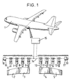
- Figure 1 shows a schematic representation of a trailing edge flap actuation system and its location with respect to the aircraft 1. The embodiment could also equally be applied to leading edge devices.
- the aircraft has four trailing edge control surfaces 2,3,4 and 5.
- Each flight control surface has two associated actuators, elements 6 through to 13. All the actuators are interconnected by a synchronising cable 14.
- a control manifold 15 directs hydraulic fluid to the actuators to cause them to either deploy or retract the control surfaces.
- Position transducers 18 and 19 are located at either wing tip end of the synchronising cable to measure the position of the control surfaces. Outputs of the transducers 18 and 19 are provided to a data processor which compares the achieved position with that selected and also monitors for asymmetries between the two wings.
- braking devices 16 and 17 positioned in each wing are invoked to retain the flight control surfaces in a fixed position.
- the braking devices 16 and 17 may either be electrically or hydraulically operated.
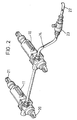
- the actuator 11 has an attachment point 20 which is connected to the airframe (not shown).
- the actuator is also attached to a linkage arrangement (not shown), connected to the flight control surface (not shown), via an eye-end attachment 21.
- the actuators 10 and 11 are connected together by the synchronising cable 14 which runs within a hydraulic fluid supply line 22 which provides working fluid to extend the actuators.
- a hydraulic connection from the manifold 15 to the actuators is made via a coupling 23.
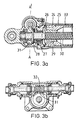
- the actuator comprises a piston 24 which translates within a cylinder and is in substantially fluid sealed engagement therewith.
- the piston is connected to eye-end attachment 21.
- Hydraulic fluid can be introduced into a first chamber 26 via drillings 27 connecting the chamber 26 to a further chamber 28 which is in fluid flow communication with the hydraulic supply line 22.
- Introduction of fluid into the chamber 26 causes the piston 24 to extend from the cylinder 25.
- Motion of the piston causes a nut 29 which is affixed thereto to move longitudinally with respect to a lead screw 30 thereby causing the lead screw 30 to rotate as the actuator is operated.
- Rotation of the lead screw 30 is transmitted via wheel and worm 31 and 32 respectively, to the synchronising cable 14 in order to transfer rotary motion to the cable.
- Hydraulic fluid may also be introduced into a second chamber 33 from a further hydraulic line in order to retract the actuator.
- the other chamber is connected to a return line, thereby ensuring that the actuator does not become hydraulically locked.
- the actuators may be of the regenerative type, where during normal deployment, both chambers 26 and 33 are pressurised, but the unequal surface area across the piston 24 causes the actuator to move to the deployed position. Motion to the undeployed position is achieved by aerodynamic forces acting on the associated control surface.
- Figure 4 presents a schematic representation of the synchronising elements.
- the transfer efficiency between the actuator and synchronising cable is quite low. More specifically, the output shaft undergoes many turns during the stroke of the actuator, and consequently only a relatively low braking torque need be applied at the synchronising cable, in order to prevent deployment of the actuator. Furthermore, it is not possible to drive the actuator merely by applying a torque at the synchronising cable.
- the actuators 10 and 11 are connected in series, if during deployment one actuator tries to move in advance of its neighbour, the synchronising cable 14 will become wound up and will exert a restoring torque on the leading actuator 11 thereby braking its motion and enabling the lagging actuator 10 to catch up. Once the actuators become synchronised, the synchronising cable is returned to a low torque state and the leading actuator 11 can continue to move again.
- Figure 5 provides a circuit diagram of the control manifold 34 including the secondary power supply system.
- the control manifold is configured to position the control surfaces at discrete positions using a series of solenoid operated valves 35,36,37 and the extend/retract/lock control valve 38.
- Hydraulic fluid is directed to the control valve 38 via operation of an enable/disable valve 36 from the aircraft hydraulic supply line (Ps).
- Extension or retraction of the actuators is determined by operation of either pilot solenoid valve 35 or 37, which directs hydraulic fluid to move the control valve 38 in the appropriate direction, to connect either the hydraulic supply to the actuators extend 22, or retract lines 39.
- a switch-over valve 40 detects loss of fluid from the aircraft hydraulic supply and switches hydraulic connection to the secondary system. Hydraulic fluid is then drawn from an accumulator 41 via an electric motor/pump arrangement 42 to provide hydraulic power to the system.
- control manifold may be configured to allow the position of the flight control surfaces to be continuously variable in an active manner.
- solenoid operated valves would be dispensed with and replaced with either an electro-hydraulic servo valve, or direct drive valve arrangement.
- the secondary power supply is considered an optional feature of the design, its necessity dictated by the reliability requirement for the complete actuation system.
- Figure 6 shows an alternative arrangement for the actuation system, whereby each of the actuators 6 through to 13 are interconnected using a down drive shaft/cable 43 through to 50, and a down drive gearbox 51 through to 58 connected to the synchronising cable 14.
- This arrangement is of benefit where the aircraft wing structure does not permit the routing of the synchronising cable directly between the head ends of the actuators. This simplifies retro-fitting of the system to existing aircraft.
- Figure 7 shows a modification of the hydraulic arrangement shown in figure 5.
- a changeover valve 70 is provided intermediate first and second hydraulic supplies and the control manifold 34.
- the changeover valve is a semi-automatic valve allowing protection from a single fault which might otherwise result in loss of both hydraulic supplies.
- the changeover valve comprises first and second mechanically linked spool valves 72 and 74.
- the valves are substantially identical and are arranged in opposition.
- a valve member 76 carries three enlarged portions 78, 80 and 82 which are in sliding substantially fluid sealed contact with a cylinder 84 formed within the valve housing.
- the first and second valves have connections P1, R1 and P2, R2 respectively to the individual hydraulic supplies and have outputs forming a common connection to the control manifold 34. In the position shown in figure 7, both the hydraulic supplies are isolated from the control manifold 34.
- Each of the first and second spool valves is provided with a piston and cylinder arrangement 86.
- the piston and cylinder arrangement on the first valve 72 connected to the primary hydraulic supply is in permanent fluid flow communication with the primary hydraulic supply P1.
- the piston and cylinder arrangement of the second valve 74 connected to the secondary hydraulic supply is selectively collectable to the second hydraulic supply via a solenoid operated valve 88.
- the changeover valve operates during every flight. When both hydraulic systems are shut down the valve is spring hind to the centred null position shown in figure 7. When both hydraulic systems are powered up, the connection from the supply line P1 to the piston and cylinder arrangement 86 of the left hand side of the valve as shown in figure 7 biases the changeover valve spool to connect the primary hydraulics supply to the control manifold. This regular movement of the valve prevents silting of the valve and possible dormant failure of the changeover valve spool.
- a pressure switch (not shown) is provided as part of the control manifold for sensing the pressure of the hydraulic supply. Failure of the primary hydraulic supply is sensed by the pressure switch, which can then send a signal to the system control in order to cause the secondary hydraulic supply to be connected to the control manifold 34 by operation of the solenoid valve 88 when it is desired to operate the flaps. Thus the secondary hydraulic supply is only selected upon flap demand. Once the flaps have been moved to the required position, the solenoid valve 88 is de-energised thereby allowing the changeover valve to return to the position where both hydraulic supplies are isolated. This safeguards the backup hydraulic supply against being compromised due to exposure to a leak. The secondary hydraulic supply is only exposed to the possible leak for a brief duration of time when it is required to actuate the flight control surfaces.
- the central spool 76 may be divided as two abutting halfs. This allows the possibility of the spool portion associated with the second hydraulic supply to be moved in order to connect the second hydraulic supply to the control manifold 34 even in the event that the spool portion associated with the first hydraulic supply has become jammed in the changeover valve.
Landscapes
- Engineering & Computer Science (AREA)
- Aviation & Aerospace Engineering (AREA)
- Physics & Mathematics (AREA)
- Fluid Mechanics (AREA)
- Mechanical Engineering (AREA)
- General Engineering & Computer Science (AREA)
- Automation & Control Theory (AREA)
- Fluid-Pressure Circuits (AREA)
- Transmission Devices (AREA)
Description
- The present invention relates to a flight control surface actuation system. Such an actuation system is used to deploy and retract aircraft flight control surfaces, typically trailing edge flaps and leading edge high lift devices.
- The flight control surfaces are moved between the high lift and normal states by actuators. It is desirable that the deployment of the flight control surfaces occurs at a steady rate, and that deployment of the surfaces along one side of the aircraft occurs in synchronisation with deployment of the surfaces along the other side of the aircraft. Any asymmetry can give rise to severe difficulties controlling the aircraft.
- US-A-2 819 589 discloses a fluid pressure actuator, and in particular a self-locking actuator having means for effecting synchronous operation with other like actuators. Flexible shafts provide connections between actuators such that under normal operating conditions the actuators movements are synchronised to one another. However, should the locking mechanism of one of the actuators fail such that the actuator is locked stationary, US-A-2 819 589 discloses that the flexible shafts permit movement of the other actuators. Thus an asymmetry in the position of the actuators may occur, which as described above, is extremely undesirable in flight surface control systems. US-A-2 819 589 cannot therefore be said to provide full synchronisation of actuators in all situations.
- According to the present invention, there is provided a flight control surface actuation system, comprising at least three linear hydraulic actuators which control the position of aircraft flight surfaces, in which each actuator comprises a gear arrangement and is mechanically synchronised with the other actuators via a synchronising element connected between said gear arrangements characterised in that a gear ratio of said gear arrangement is such that a motion of a first actuator in advance of that of a neighbouring second actuator induces a torque in the synchronising element sufficient to cause the first actuator to be braked thereby allowing the second actuator to catch up, the gear ratio also being such that insufficient torque is transferred through the synchronising element to drive the second actuator.
- It is thus possible to synchronise the flight control surfaces of an aircraft using a mechanical interconnection, whilst retaining the use of a linear hydraulic actuation system.
- This is particularly beneficial as such a system provides cost and weight advantages when compared with prior art synchronised actuation systems, without any compromise to airworthiness requirements for asymmetry protection.
- Preferably, the synchronising element is a cable.
- Advantageously, the cable is flexible and can be routed along non-linear paths, which obviates the need to introduce universal joints and steady bearings.
- Preferably, the synchronising cable is located internally to a hydraulic fluid supply line for the actuators. This simplifies the routing of the synchronising element and also protects the cable from possible damage. Furthermore, it removes the necessity to use rotary shaft seals in such a high pressure system.
- Preferably, the synchronising element is coupled to each actuator in series. This simplifies installation. The synchronising elements for either wing are connected together via a coupling located central to the actuation system. The coupling also serves as a junction to supply oil to the hydraulic extend line. In an alternative arrangement, individual down drive cables may be used to interconnect each actuator from a common synchronising element. To account for airframe tolerances the synchronising element coupling may also comprise a backlash device, to provide a degree of lost motion between left and right hand wing actuators.
- Preferably, each actuator includes an integral synchronisation mechanism. The synchronisation mechanism may comprise a nut retained by a piston of the actuator. The nut also threadedly engages a lead screw. The lead screw is coupled to the gear arrangement, which may be a worm and wheel, situated in the gear head of the actuator.
- The worm gear is of a double enveloping arrangement, such that its output is connected to the neighbouring actuators using a flexible cable. During extension and or retraction of the actuators, the nut translates with the piston as it moves under the action of hydraulic pressure. The linear movement of the nut thus causes the lead screw to rotate, thus transferring rotary movement to the flexible cable, via the wheel and worm.
- Advantageously, the use of a worm and wheel gear allows a high gear ratio to be selected. This, along with the characteristic of a low transfer efficiency, ensures torques induced into the synchronisation element are comparatively low.
- The inefficiency of the worm and wheel ensures that the torque developed in the synchronisation element is sufficient to resist differential movement between the actuators and provides good synchronising accuracy.
- It is thus possible to use relatively light (i.e. not substantial) synchronising element, as the torques acting thereon are relatively small. This avoids the weight implications of prior art synchronised actuation systems, which employ, relatively large synchronising shafts to transfer torque between control surface actuators.
- Advantageously, the actuators are connected sequentially along the synchronising element. Differential movement between actuators is inhibited, thus providing a means of mechanical synchronisation.
- As a consequence of one actuator travelling in advance of the remaining actuators, a torque is induced into the flexible cable. The torque resists further rotation of the worm/wheel of the leading actuator thus preventing further linear movement until the lagging actuators maintain the same position. At this point the torque exerted on the leading actuator is removed and the actuators are free to move in unison. Hence, even under asymmetric wing loading the actuators will still extend and retract at the same rate and to the same position, within limits.
- Preferably, the synchronising element terminates at a braking device for either wing. Thus, in the event of failure of the synchronising element, the braking devices can be operated in order to lock the flight control surfaces in a fixed position. This action limits the degree of asymmetry which may occur. Hydraulic locking of the actuators may also be provided.
- Preferably, at least one position transducer is used to monitor the position of the control surfaces, with respect to the commanded position. Also, comparison between left and right hand wings can be undertaken to detect for an asymmetry condition, thus necessitating the application of the braking devices.
- The control manifold may also be configured with a secondary power supply, comprising an electric motor, hydraulic pump and fluid reservoir. The secondary power supply system is completely segregated from the main hydraulic power supply.
- Advantageously, the secondary power supply system ensures that the actuation system achieves recognised reliability targets for transport availability.
- The present invention will further be described by way of example, with reference to the accompanying drawings, in which:
- Figure 1 is a schematic view of an aircraft incorporating an actuation system constituting an embodiment of the present invention;
- Figure 2 is a perspective schematic diagram illustrating part of the actuation system;
- Figures 3a and 3b are sections through an actuator used in the arrangement shown in Figure 1 and Figure 3c is a plan view of the actuator;
- Figure 4 is a schematic diagram of two synchronising elements;
- Figure 5 illustrates the circuit design of the control manifold;
- Figure 6 shows an alternative arrangement, using down drive cables; and Figure 7 shows a modification to the hydraulic circuit.
-
- Figure 1 shows a schematic representation of a trailing edge flap actuation system and its location with respect to the
aircraft 1. The embodiment could also equally be applied to leading edge devices. - As illustrated, the aircraft has four trailing
edge control surfaces 2,3,4 and 5. Each flight control surface has two associated actuators,elements 6 through to 13. All the actuators are interconnected by a synchronisingcable 14. Acontrol manifold 15 directs hydraulic fluid to the actuators to cause them to either deploy or retract the control surfaces.Position transducers transducers braking devices braking devices - Two of the
actuators actuator 11 has anattachment point 20 which is connected to the airframe (not shown). The actuator is also attached to a linkage arrangement (not shown), connected to the flight control surface (not shown), via an eye-end attachment 21. Theactuators cable 14 which runs within a hydraulicfluid supply line 22 which provides working fluid to extend the actuators. A hydraulic connection from the manifold 15 to the actuators is made via acoupling 23. - A part section through a single actuator is illustrated in Figures 3a and 3b.
- The actuator comprises a
piston 24 which translates within a cylinder and is in substantially fluid sealed engagement therewith. The piston is connected to eye-end attachment 21. Hydraulic fluid can be introduced into afirst chamber 26 viadrillings 27 connecting thechamber 26 to afurther chamber 28 which is in fluid flow communication with thehydraulic supply line 22. Introduction of fluid into thechamber 26 causes thepiston 24 to extend from thecylinder 25. Motion of the piston causes anut 29 which is affixed thereto to move longitudinally with respect to alead screw 30 thereby causing thelead screw 30 to rotate as the actuator is operated. Rotation of thelead screw 30 is transmitted via wheel andworm cable 14 in order to transfer rotary motion to the cable. - Hydraulic fluid may also be introduced into a
second chamber 33 from a further hydraulic line in order to retract the actuator. When one chamber is connected to a source of hydraulic pressure, the other chamber is connected to a return line, thereby ensuring that the actuator does not become hydraulically locked. - Alternatively, the actuators may be of the regenerative type, where during normal deployment, both
chambers piston 24 causes the actuator to move to the deployed position. Motion to the undeployed position is achieved by aerodynamic forces acting on the associated control surface. - Figure 4 presents a schematic representation of the synchronising elements. It will be noted that the transfer efficiency between the actuator and synchronising cable is quite low. More specifically, the output shaft undergoes many turns during the stroke of the actuator, and consequently only a relatively low braking torque need be applied at the synchronising cable, in order to prevent deployment of the actuator. Furthermore, it is not possible to drive the actuator merely by applying a torque at the synchronising cable. Thus, when the
actuators cable 14 will become wound up and will exert a restoring torque on the leadingactuator 11 thereby braking its motion and enabling the laggingactuator 10 to catch up. Once the actuators become synchronised, the synchronising cable is returned to a low torque state and the leadingactuator 11 can continue to move again. - Figure 5 provides a circuit diagram of the
control manifold 34 including the secondary power supply system. In this example, the control manifold is configured to position the control surfaces at discrete positions using a series of solenoid operatedvalves lock control valve 38. Hydraulic fluid is directed to thecontrol valve 38 via operation of an enable/disable valve 36 from the aircraft hydraulic supply line (Ps). Extension or retraction of the actuators is determined by operation of eitherpilot solenoid valve control valve 38 in the appropriate direction, to connect either the hydraulic supply to the actuators extend 22, or retractlines 39. - If a failure in the aircraft hydraulic supply line occurs, the actuation system may still be operated from the secondary power supply. A switch-over
valve 40 detects loss of fluid from the aircraft hydraulic supply and switches hydraulic connection to the secondary system. Hydraulic fluid is then drawn from anaccumulator 41 via an electric motor/pump arrangement 42 to provide hydraulic power to the system. - In an alternative arrangement, the control manifold may be configured to allow the position of the flight control surfaces to be continuously variable in an active manner. In this instance, the solenoid operated valves would be dispensed with and replaced with either an electro-hydraulic servo valve, or direct drive valve arrangement.
- The secondary power supply is considered an optional feature of the design, its necessity dictated by the reliability requirement for the complete actuation system.
- Figure 6 shows an alternative arrangement for the actuation system, whereby each of the
actuators 6 through to 13 are interconnected using a down drive shaft/cable 43 through to 50, and adown drive gearbox 51 through to 58 connected to the synchronisingcable 14. This arrangement is of benefit where the aircraft wing structure does not permit the routing of the synchronising cable directly between the head ends of the actuators. This simplifies retro-fitting of the system to existing aircraft. - Figure 7 shows a modification of the hydraulic arrangement shown in figure 5. A
changeover valve 70 is provided intermediate first and second hydraulic supplies and thecontrol manifold 34. The changeover valve is a semi-automatic valve allowing protection from a single fault which might otherwise result in loss of both hydraulic supplies. - The changeover valve comprises first and second mechanically linked
spool valves valve member 76 carries threeenlarged portions cylinder 84 formed within the valve housing. - The first and second valves have connections P1, R1 and P2, R2 respectively to the individual hydraulic supplies and have outputs forming a common connection to the
control manifold 34. In the position shown in figure 7, both the hydraulic supplies are isolated from thecontrol manifold 34. Each of the first and second spool valves is provided with a piston andcylinder arrangement 86. The piston and cylinder arrangement on thefirst valve 72 connected to the primary hydraulic supply is in permanent fluid flow communication with the primary hydraulic supply P1. The piston and cylinder arrangement of thesecond valve 74 connected to the secondary hydraulic supply is selectively collectable to the second hydraulic supply via a solenoid operatedvalve 88. - The changeover valve operates during every flight. When both hydraulic systems are shut down the valve is spring biaised to the centred null position shown in figure 7. When both hydraulic systems are powered up, the connection from the supply line P1 to the piston and
cylinder arrangement 86 of the left hand side of the valve as shown in figure 7 biases the changeover valve spool to connect the primary hydraulics supply to the control manifold. This regular movement of the valve prevents silting of the valve and possible dormant failure of the changeover valve spool. - In the event that the primary hydraulic supply pressure is lost, the valve becomes centred to the null position by the
internal springs control manifold 34, thereby avoiding the loss of both hydraulic supplies through a common fault. - A pressure switch (not shown) is provided as part of the control manifold for sensing the pressure of the hydraulic supply. Failure of the primary hydraulic supply is sensed by the pressure switch, which can then send a signal to the system control in order to cause the secondary hydraulic supply to be connected to the
control manifold 34 by operation of thesolenoid valve 88 when it is desired to operate the flaps. Thus the secondary hydraulic supply is only selected upon flap demand. Once the flaps have been moved to the required position, thesolenoid valve 88 is de-energised thereby allowing the changeover valve to return to the position where both hydraulic supplies are isolated. This safeguards the backup hydraulic supply against being compromised due to exposure to a leak. The secondary hydraulic supply is only exposed to the possible leak for a brief duration of time when it is required to actuate the flight control surfaces. - As shown in figure 7, the
central spool 76 may be divided as two abutting halfs. This allows the possibility of the spool portion associated with the second hydraulic supply to be moved in order to connect the second hydraulic supply to thecontrol manifold 34 even in the event that the spool portion associated with the first hydraulic supply has become jammed in the changeover valve. - It is thus possible to provide a lightweight and reliable flight control surface actuation system.
Claims (14)
- A flight control surface actuation system, comprising at least three linear hydraulic actuators (6-13) which control the position of aircraft flight surfaces (2-5), in which each actuator (6-13) comprises a gear arrangement (31, 32) and is mechanically synchronised with the other actuators via a synchronising element (14) connected between said gear arrangements characterised in that a gear ratio of said gear arrangement is such that a motion of a first actuator in advance of that of a neighbouring second actuator induces a torque in the synchronising element sufficient to cause the first actuator to be braked thereby allowing the second actuator to catch up, the gear ratio also being such that insufficient torque is transferred through the synchronising element (14) to drive the second actuator.
- A flight control surface actuation system as claimed in claim 1, characterised in that the synchronising element (14) is a cable.
- A flight control surface actuation system as claimed in claim 2, characterised in that the cable (14) is located internally to a hydraulic fluid supply line (22) for the actuators.
- A flight control surface actuation system as claimed in any one of the preceding claims, characterised in that the synchronising element (14) is coupled to each actuator (6-13) in series.
- A flight control surface actuation system as claimed in any one of the preceding claims, characterised in that the synchronising elements for opposed wings are connected together via a coupling (23) located central to the actuation system.
- A flight control surface actuation system as claimed in claim 5, characterised in that a backlash device is also provided to provide a degree of lost motion between left and right hand wing actuators.
- A flight control surface actuation system as claimed in any one of the preceding claims, characterised in that each actuator includes an internal synchronisation mechanism.
- A flight control surface actuation system as claimed in claim 7, characterised in that the internal synchronisation mechanism comprises a nut (29) retained by a piston (24) of the actuator, the nut (29) threadedly engages a lead screw (30) which is coupled to the gear arrangement (31, 32) connected to the synchronising element (14).
- A flight control surface actuation system as claimed in claim 8, characterised in that the gear arrangement comprises a worm gear (31) and a wheel gear (32) arranged such that the torque developed in the synchronising element (14) is sufficient to resist differential movement between actuators (6-13).
- A flight control surface actuation system as claimed in any one of the preceding claims, characterised by further comprising a braking device (16, 17) for each wing for locking the actuators (6-13) in the event of failure of the synchronising element (14).
- A flight control surface actuation system as claimed in any one of the preceding claims, characterised by at least one position transducer (18, 19) for monitoring the positions of the flight control surfaces with respect to the commanding positions.
- A flight control surface actuation system as claimed in any one of the preceding claims, further comprising a back-up supply of hydraulic fluid, and means for supplying that fluid under pressure to operate the actuators in the event of failure of a primary hydraulic supply.
- A flight control surface actuation system as claimed in any one of the preceding claims, characterised in that there is a first supply of hydraulic fluid under pressure, an second supply of hydraulic fluid under pressure and a changeover valve 70 arranged to connect the first supply of hydraulic fluid to the actuators when the pressure thereof exceeds a first value and to selectively connect the second supply to the actuators only when commanded.
- A flight control surface actuation system as claimed in any one of the preceding claims, characterised in that each actuator (6-13) is connected to the synchronising element (14) via a respective down drive gearbox (51-58) and down drive element (43-50).
Applications Claiming Priority (2)
| Application Number | Priority Date | Filing Date | Title |
|---|---|---|---|
| GB9619488 | 1996-09-18 | ||
| GBGB9619488.1A GB9619488D0 (en) | 1996-09-18 | 1996-09-18 | Flight control surface actuation system |
Publications (3)
| Publication Number | Publication Date |
|---|---|
| EP0831027A2 EP0831027A2 (en) | 1998-03-25 |
| EP0831027A3 EP0831027A3 (en) | 2000-04-19 |
| EP0831027B1 true EP0831027B1 (en) | 2003-11-12 |
Family
ID=10800123
Family Applications (1)
| Application Number | Title | Priority Date | Filing Date |
|---|---|---|---|
| EP97307236A Expired - Lifetime EP0831027B1 (en) | 1996-09-18 | 1997-09-16 | Flight control surface actuation system |
Country Status (5)
| Country | Link |
|---|---|
| US (1) | US6076767A (en) |
| EP (1) | EP0831027B1 (en) |
| JP (1) | JPH10157698A (en) |
| DE (1) | DE69726082T2 (en) |
| GB (1) | GB9619488D0 (en) |
Families Citing this family (52)
| Publication number | Priority date | Publication date | Assignee | Title |
|---|---|---|---|---|
| USRE44313E1 (en) | 1996-10-22 | 2013-06-25 | The Boeing Company | Airplane with unswept slotted cruise wing airfoil |
| JP4261024B2 (en) * | 2000-05-17 | 2009-04-30 | 株式会社小松製作所 | Anti-silting control device |
| DE10160315A1 (en) * | 2001-12-07 | 2003-11-13 | Airbus Gmbh | Device for the approach control of an aircraft |
| US7258308B2 (en) * | 2002-07-02 | 2007-08-21 | The Boeing Company | Method and apparatus for controlling airflow with a gapped trailing edge device having a flexible flow surface |
| US7059563B2 (en) * | 2003-06-03 | 2006-06-13 | The Boeing Company | Systems, apparatuses, and methods for moving aircraft control surfaces |
| US7243881B2 (en) * | 2003-06-03 | 2007-07-17 | The Boeing Company | Multi-function trailing edge devices and associated methods |
| US6799739B1 (en) | 2003-11-24 | 2004-10-05 | The Boeing Company | Aircraft control surface drive system and associated methods |
| US7424350B2 (en) * | 2004-02-02 | 2008-09-09 | The Boeing Company | Vehicle control systems and corresponding sizing methods |
| US7357358B2 (en) | 2004-02-27 | 2008-04-15 | The Boeing Company | Aircraft leading edge device systems and corresponding sizing methods |
| US6978971B1 (en) * | 2004-06-15 | 2005-12-27 | The Boeing Company | Methods and apparatuses for controlling airflow proximate to engine/airfoil systems |
| US7270305B2 (en) | 2004-06-15 | 2007-09-18 | The Boeing Company | Aircraft leading edge apparatuses and corresponding methods |
| US7770842B2 (en) * | 2004-08-24 | 2010-08-10 | Honeywell International Inc. | Aircraft flight control surface actuation system communication architecture |
| US7494094B2 (en) | 2004-09-08 | 2009-02-24 | The Boeing Company | Aircraft wing systems for providing differential motion to deployable lift devices |
| DE102004047008A1 (en) * | 2004-09-28 | 2006-03-30 | Liebherr-Aerospace Lindenberg Gmbh | Device for adjusting aircraft altitude fins |
| US7264206B2 (en) | 2004-09-30 | 2007-09-04 | The Boeing Company | Leading edge flap apparatuses and associated methods |
| US7322547B2 (en) | 2005-01-31 | 2008-01-29 | The Boeing Company | Aerospace vehicle leading edge slat devices and corresponding methods |
| US7338018B2 (en) | 2005-02-04 | 2008-03-04 | The Boeing Company | Systems and methods for controlling aircraft flaps and spoilers |
| US7309043B2 (en) * | 2005-04-27 | 2007-12-18 | The Boeing Company | Actuation device positioning systems and associated methods, including aircraft spoiler droop systems |
| US7300021B2 (en) * | 2005-05-20 | 2007-11-27 | The Boeing Company | Aerospace vehicle fairing systems and associated methods |
| US7721999B2 (en) | 2005-05-20 | 2010-05-25 | The Boeing Company | Aerospace vehicle fairing systems and associated methods |
| US7367530B2 (en) * | 2005-06-21 | 2008-05-06 | The Boeing Company | Aerospace vehicle yaw generating systems and associated methods |
| US20070007385A1 (en) * | 2005-06-27 | 2007-01-11 | Honeywell International, Inc. | Electric flight control surface actuation system electronic architecture |
| US7549605B2 (en) * | 2005-06-27 | 2009-06-23 | Honeywell International Inc. | Electric flight control surface actuation system for aircraft flaps and slats |
| US7500641B2 (en) | 2005-08-10 | 2009-03-10 | The Boeing Company | Aerospace vehicle flow body systems and associated methods |
| US7611099B2 (en) | 2005-09-07 | 2009-11-03 | The Boeing Company | Seal assemblies for use with drooped spoilers and other control surfaces on aircraft |
| US7708231B2 (en) | 2005-11-21 | 2010-05-04 | The Boeing Company | Aircraft trailing edge devices, including devices having forwardly positioned hinge lines, and associated methods |
| US7475854B2 (en) | 2005-11-21 | 2009-01-13 | The Boeing Company | Aircraft trailing edge devices, including devices with non-parallel motion paths, and associated methods |
| US7322545B2 (en) * | 2005-12-29 | 2008-01-29 | The Boeing Company | Structural mechanism for unlocking and engaging a controllable surface on a hinged platform (wing) |
| US7578484B2 (en) | 2006-06-14 | 2009-08-25 | The Boeing Company | Link mechanisms for gapped rigid krueger flaps, and associated systems and methods |
| US20080203223A1 (en) * | 2006-06-22 | 2008-08-28 | Cyrot Luc P | Aircraft stabilizer actuator |
| US7641145B2 (en) * | 2006-11-21 | 2010-01-05 | Eaton Corporation | Apparatus for moving a control surface |
| DE102007046707A1 (en) * | 2007-09-28 | 2009-04-09 | Liebherr-Aerospace Lindenberg Gmbh | Sensor system for monitoring the synchronous operation of control surfaces of an aircraft |
| US8210206B2 (en) * | 2007-11-27 | 2012-07-03 | Woodward Hrt, Inc. | Dual redundant servovalve |
| US7954769B2 (en) | 2007-12-10 | 2011-06-07 | The Boeing Company | Deployable aerodynamic devices with reduced actuator loads, and related systems and methods |
| US7766282B2 (en) | 2007-12-11 | 2010-08-03 | The Boeing Company | Trailing edge device catchers and associated systems and methods |
| DE102008022092A1 (en) * | 2008-05-05 | 2009-11-19 | Airbus Deutschland Gmbh | Fault-tolerant control system for adjusting the flaps of an aircraft with adjustable kinematics with a fixed axis of rotation |
| US8382045B2 (en) | 2009-07-21 | 2013-02-26 | The Boeing Company | Shape-changing control surface |
| DE102010047540A1 (en) * | 2010-10-05 | 2012-04-05 | Airbus Operations Gmbh | High-lift system for a wing of an aircraft |
| FR2972175B1 (en) * | 2011-03-01 | 2013-10-25 | Sagem Defense Securite | METHOD FOR SIMULTANEOUSLY CONTROLLING AIRCRAFT FLIGHT DISPLACEMENT ACTUATORS, AIRCRAFT FLIGHT AND AIRCRAFT FLIGHT DEVICE PROVIDED WITH SUCH A DEVICE |
| US8800594B2 (en) | 2012-02-02 | 2014-08-12 | Honeywell International Inc. | Gas turbine engine fuel return valve and system |
| JP5905294B2 (en) * | 2012-02-27 | 2016-04-20 | ナブテスコ株式会社 | Aircraft actuator hydraulic system |
| FR2992629B1 (en) * | 2012-06-27 | 2014-09-12 | Airbus Operations Sas | DEVICE FOR MECHANICALLY CONNECTING A GOVERNMENT TO A FIXED AIRCRAFT STRUCTURAL ELEMENT AND AN AIRCRAFT SAILING MEMBER EQUIPPED WITH SAID DEVICE |
| DE102013103428B4 (en) * | 2013-04-05 | 2023-11-16 | Webasto-Edscha Cabrio GmbH | Actuating device for an adjustable roof system of a motor vehicle |
| US10113565B2 (en) | 2014-06-03 | 2018-10-30 | Moog Inc. | Engine nozzle synchronization system |
| FR3047725B1 (en) * | 2016-02-12 | 2018-01-26 | Airbus Operations | AIRCRAFT HYPERSUSTENT DEVICE EQUIPPED WITH AT LEAST ONE DIFFERENTIATED COUPLING SYSTEM |
| EP3444483B1 (en) | 2017-08-17 | 2020-12-16 | Goodrich Actuation Systems Limited | Multi-cylinder hydraulic actuator system |
| EP3713844A1 (en) | 2017-11-21 | 2020-09-30 | Bombardier Inc. | System and method for actuating high-lift flight control surfaces |
| US10773795B2 (en) * | 2018-09-24 | 2020-09-15 | The Boeing Company | Distributed linear hydraulic high lift actuation system with synchronization members |
| WO2021034362A2 (en) | 2019-05-22 | 2021-02-25 | Moog Inc. | Preloaded torque shaft and the flight control driveline made therewith |
| EP4030079A1 (en) | 2021-01-15 | 2022-07-20 | Goodrich Actuation Systems Limited | Rotary geared actuator |
| EP4086169B1 (en) * | 2021-05-06 | 2025-10-15 | Safran Landing Systems Canada Inc. | Aircraft braking system |
| US12420913B2 (en) * | 2024-02-02 | 2025-09-23 | Hamilton Sundstrand Corporation | Hydraulic drag brake |
Family Cites Families (15)
| Publication number | Priority date | Publication date | Assignee | Title |
|---|---|---|---|---|
| US2343912A (en) * | 1940-01-17 | 1944-03-14 | Pesco Products Co | Flow equalizer |
| US2376320A (en) * | 1942-05-11 | 1945-05-22 | Douglas Aircraft Co Inc | Hydraulic synchronizer |
| US2386219A (en) * | 1943-04-15 | 1945-10-09 | Pesco Products Co | Multiple unit compact gear divider assembly |
| US2657539A (en) * | 1952-03-13 | 1953-11-03 | Gen Motors Corp | Synchronized power transmitter |
| US2819589A (en) * | 1954-04-01 | 1958-01-14 | Gen Motors Corp | Fluid pressure actuator and synchronizing means therefor |
| GB1098194A (en) * | 1964-07-07 | 1968-01-10 | Hobson Ltd H M | Improvements in position control servo systems |
| US3515033A (en) * | 1967-08-04 | 1970-06-02 | Gen Electric | Actuators |
| US3691911A (en) * | 1970-06-25 | 1972-09-19 | Clark Equipment Co | Power device with synchronization of plural actuators |
| FR2347257A1 (en) * | 1976-04-05 | 1977-11-04 | Aerospatiale | SERVOCONTROL DEVICE FOR THE CONTROL OF AN AIRCRAFT RUDDER |
| GB1557706A (en) * | 1977-04-13 | 1979-12-12 | British Aircraft Corp Ltd | Aircraft hydraulic systems |
| US4485725A (en) * | 1982-05-13 | 1984-12-04 | Pneumo Corporation | Actuator system including hydraulically synchronized actuators |
| US4521060A (en) * | 1983-11-17 | 1985-06-04 | Sundstrand Corporation | Hydraulic asymmetry detector |
| US5628477A (en) * | 1995-02-13 | 1997-05-13 | The Boeing Company | Auxiliary airfoil lost motion detector and actuator |
| US5680124A (en) * | 1995-05-15 | 1997-10-21 | The Boeing Company | Skew and loss detection system for adjacent high lift devices |
| US5873548A (en) * | 1996-09-06 | 1999-02-23 | The Boeing Company | Airacraft hydraulic system for improved reliability of integrated hydraulic propulsion controls |
-
1996
- 1996-09-18 GB GBGB9619488.1A patent/GB9619488D0/en active Pending
-
1997
- 1997-09-16 DE DE69726082T patent/DE69726082T2/en not_active Expired - Lifetime
- 1997-09-16 EP EP97307236A patent/EP0831027B1/en not_active Expired - Lifetime
- 1997-09-17 US US08/931,670 patent/US6076767A/en not_active Expired - Lifetime
- 1997-09-18 JP JP9253706A patent/JPH10157698A/en active Pending
Also Published As
| Publication number | Publication date |
|---|---|
| DE69726082D1 (en) | 2003-12-18 |
| JPH10157698A (en) | 1998-06-16 |
| EP0831027A3 (en) | 2000-04-19 |
| US6076767A (en) | 2000-06-20 |
| DE69726082T2 (en) | 2004-08-26 |
| EP0831027A2 (en) | 1998-03-25 |
| GB9619488D0 (en) | 1996-10-30 |
Similar Documents
| Publication | Publication Date | Title |
|---|---|---|
| US6076767A (en) | Flight control surface actuation system | |
| EP3549857B1 (en) | Flap actuator system | |
| EP3620374B1 (en) | Distributed trailing edge wing flap systems | |
| US10538310B2 (en) | Near synchronous distributed hydraulic motor driven actuation system | |
| US5743490A (en) | Flap/slat actuation system for an aircraft | |
| US7870726B2 (en) | Local backup hydraulic actuator for aircraft control systems | |
| JP3162139B2 (en) | Hydrostatic mode hydraulic actuator, preferably functioning in an emergency, and a steering system equipped with the actuator | |
| US10926867B2 (en) | Distributed trailing edge wing flap systems | |
| CN110304238B (en) | Distributed trailing edge wing flap system | |
| EP3514056B1 (en) | Distributed trailing edge wing flap systems | |
| CN111196348A (en) | High lift actuation system with independent actuation control | |
| CN111196349A (en) | High lift actuation system with centralized inboard actuation control and independent outboard actuation control | |
| US11498658B2 (en) | System for an aircraft wing | |
| US4825748A (en) | Hydraulic actuator synchronization apparatus and system | |
| EP4542058A1 (en) | Three way transfer valve for parallel electrohydraulic servo valve control of actuator | |
| US20120090459A1 (en) | Floating piston actuator for operation with multiple hydraulic systems | |
| EP4542057A1 (en) | Parallel electrohydraulic servo valve controlled actuator with failure accommodation | |
| EP0256648A2 (en) | Hydraulic control system | |
| US12345323B2 (en) | Rotary EMA | |
| BR102019018348B1 (en) | WING FLAP SYSTEM FOR AN AIRCRAFT AND METHOD FOR OPERATING A WING FLAP SYSTEM |
Legal Events
| Date | Code | Title | Description |
|---|---|---|---|
| PUAI | Public reference made under article 153(3) epc to a published international application that has entered the european phase |
Free format text: ORIGINAL CODE: 0009012 |
|
| AK | Designated contracting states |
Kind code of ref document: A2 Designated state(s): DE FR GB IT |
|
| AX | Request for extension of the european patent |
Free format text: AL;LT;LV;RO;SI |
|
| PUAL | Search report despatched |
Free format text: ORIGINAL CODE: 0009013 |
|
| AK | Designated contracting states |
Kind code of ref document: A3 Designated state(s): AT BE CH DE DK ES FI FR GB GR IE IT LI LU MC NL PT SE |
|
| AX | Request for extension of the european patent |
Free format text: AL;LT;LV;RO;SI |
|
| RIC1 | Information provided on ipc code assigned before grant |
Free format text: 7B 64C 13/40 A, 7B 64C 13/38 B, 7F 15B 11/22 B |
|
| 17P | Request for examination filed |
Effective date: 20000602 |
|
| AKX | Designation fees paid |
Free format text: DE FR GB IT |
|
| 17Q | First examination report despatched |
Effective date: 20011206 |
|
| RAP1 | Party data changed (applicant data changed or rights of an application transferred) |
Owner name: SMITHS WOLVERHAMPTON LIMITED |
|
| GRAH | Despatch of communication of intention to grant a patent |
Free format text: ORIGINAL CODE: EPIDOS IGRA |
|
| GRAS | Grant fee paid |
Free format text: ORIGINAL CODE: EPIDOSNIGR3 |
|
| GRAA | (expected) grant |
Free format text: ORIGINAL CODE: 0009210 |
|
| AK | Designated contracting states |
Kind code of ref document: B1 Designated state(s): DE FR GB IT |
|
| REG | Reference to a national code |
Ref country code: GB Ref legal event code: FG4D |
|
| REF | Corresponds to: |
Ref document number: 69726082 Country of ref document: DE Date of ref document: 20031218 Kind code of ref document: P |
|
| ET | Fr: translation filed | ||
| PLBE | No opposition filed within time limit |
Free format text: ORIGINAL CODE: 0009261 |
|
| STAA | Information on the status of an ep patent application or granted ep patent |
Free format text: STATUS: NO OPPOSITION FILED WITHIN TIME LIMIT |
|
| 26N | No opposition filed |
Effective date: 20040813 |
|
| PG25 | Lapsed in a contracting state [announced via postgrant information from national office to epo] |
Ref country code: IT Free format text: LAPSE BECAUSE OF NON-PAYMENT OF DUE FEES Effective date: 20050916 |
|
| REG | Reference to a national code |
Ref country code: GB Ref legal event code: 732E |
|
| REG | Reference to a national code |
Ref country code: FR Ref legal event code: TP |
|
| REG | Reference to a national code |
Ref country code: GB Ref legal event code: 732E Free format text: REGISTERED BETWEEN 20100121 AND 20100127 |
|
| REG | Reference to a national code |
Ref country code: FR Ref legal event code: TP |
|
| REG | Reference to a national code |
Ref country code: FR Ref legal event code: PLFP Year of fee payment: 19 |
|
| REG | Reference to a national code |
Ref country code: FR Ref legal event code: PLFP Year of fee payment: 20 |
|
| PGFP | Annual fee paid to national office [announced via postgrant information from national office to epo] |
Ref country code: GB Payment date: 20160902 Year of fee payment: 20 Ref country code: DE Payment date: 20160921 Year of fee payment: 20 |
|
| PGFP | Annual fee paid to national office [announced via postgrant information from national office to epo] |
Ref country code: FR Payment date: 20160921 Year of fee payment: 20 |
|
| REG | Reference to a national code |
Ref country code: DE Ref legal event code: R071 Ref document number: 69726082 Country of ref document: DE |
|
| REG | Reference to a national code |
Ref country code: GB Ref legal event code: PE20 Expiry date: 20170915 |
|
| PG25 | Lapsed in a contracting state [announced via postgrant information from national office to epo] |
Ref country code: GB Free format text: LAPSE BECAUSE OF EXPIRATION OF PROTECTION Effective date: 20170915 |