EP0830909A2 - Apparatus for feeding rivets for riveting guns - Google Patents
Apparatus for feeding rivets for riveting guns Download PDFInfo
- Publication number
- EP0830909A2 EP0830909A2 EP97830449A EP97830449A EP0830909A2 EP 0830909 A2 EP0830909 A2 EP 0830909A2 EP 97830449 A EP97830449 A EP 97830449A EP 97830449 A EP97830449 A EP 97830449A EP 0830909 A2 EP0830909 A2 EP 0830909A2
- Authority
- EP
- European Patent Office
- Prior art keywords
- duct
- compressed air
- pressure
- rivets
- along
- Prior art date
- Legal status (The legal status is an assumption and is not a legal conclusion. Google has not performed a legal analysis and makes no representation as to the accuracy of the status listed.)
- Withdrawn
Links
Images
Classifications
-
- B—PERFORMING OPERATIONS; TRANSPORTING
- B21—MECHANICAL METAL-WORKING WITHOUT ESSENTIALLY REMOVING MATERIAL; PUNCHING METAL
- B21J—FORGING; HAMMERING; PRESSING METAL; RIVETING; FORGE FURNACES
- B21J15/00—Riveting
- B21J15/10—Riveting machines
- B21J15/30—Particular elements, e.g. supports; Suspension equipment specially adapted for portable riveters
- B21J15/32—Devices for inserting or holding rivets in position with or without feeding arrangements
-
- B—PERFORMING OPERATIONS; TRANSPORTING
- B21—MECHANICAL METAL-WORKING WITHOUT ESSENTIALLY REMOVING MATERIAL; PUNCHING METAL
- B21J—FORGING; HAMMERING; PRESSING METAL; RIVETING; FORGE FURNACES
- B21J15/00—Riveting
- B21J15/10—Riveting machines
- B21J15/105—Portable riveters
Definitions
- the present invention relates to a rivet feeding apparatus for riveting guns.
- the present apparatus is used specifically for automatically and continuously arming tear-off rivets pre-mounted on the tear-off nail.
- a device of the type comprising: a conveyor for rivets fitted with nail and collar, on which the rivets advance one after the other hanging by the collar with the nail facing downward; a device for upsetting the rivets exiting the conveyor; means for transporting the rivets from the upsetting device to a front arming device; and a front arming device provided to load the rivets onto a riveting gun.
- the aforesaid conveyor comprises a pneumatic feed tube in which the rivets advance with the nail facing backward with respect to the direction of travel; the upsetting device receives a rivet which exits the conveyor with the nail facing downward and arranges it with the nail facing upward and facing an inlet of the pneumatic feed tube; the rivet is pushed into the tube by the action of the compressed air and is hurled towards the arming device.
- the object of the present invention is to obviate the aforesaid limitations and drawbacks of the prior art.
- the invention solves the problem of providing an apparatus for feeding rivets for riveting guns, comprising pneumatic conveyor means able to feed the rivets to an arming device of a riveting gun, and being connected at least to one source of compressed air feeding the compressed air at a first determined pressure characterised in that said pneumatic conveyor means comprise a first and a second duct, said first duct defining the route along which the rivets are destined to flow and being at least provided first means for regulating pressure shaped and arranged in such a way as to impose to the air acting along said first duct a second determined pressure; said second duct presenting one end, opposite to the one connected to said source of compressed air, connected to a portion of said first duct arranged in proximity of said arming device; said second determined pressure which acts along said first duct being smaller than said first determined pressure which acts along said second duct.
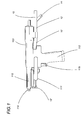
- the designation 101 indicates in its entirety an apparatus for feeding rivets 102 for rivet guns 103.
- the apparatus 101 comprises a vibration conveyor 104 for tear-off rivets 102 provided with nail 105 and collar 106.
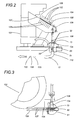
- the conveyor 104 which is housed inside an enclosed, track-mounted base not shown, is provided with a track 107, tilted, whereon the rivets 102 slide, one after the other, hanging by the collar 106 with the nail 105 facing downward.
- an arresting element 108 On the conveyor 104 is set up an arresting element 108 able to move between two positions in which, respectively, it blocks and lets pass through the rivets 102 on the track 107.
- the arresting element 108 lets the rivets 102 move forward one at a time upon external command.
- the apparatus 101 also comprises a device 109 for upsetting the rivets 102 exiting the conveyor 104 and means 110 for transporting the rivets 102 themselves to a front arming device 111 which loads the rivets 102 onto a riveting gun 103 having a stock 112 and a grip 113.
- the forward end of the stock 112 is fitted with a head 114 and the grip 113 is provided with a control push-button 115.
- the described means 110 for transporting the rivets 102 include a conveyor element comprising a duct 12 for low pressure compressed air, partly inside the aforesaid base not shown and provided with an upward facing inlet 13 for the rivets 102. More specifically, the inlet 13 is provided with a shutter 13a which opens and shuts the inlet 13 itself, which communicates with the bottom of a loading hopper 50 able to receive the rivets 102 from the vibrating conveyor 104. The rivets 102, therefore, fall into a duct 53 of a receiving element 51.
- the receiving element 51 is provided with an additional duct 52 communicating, at one of its ends, with the aforesaid internal duct 53, and at its other end with a source of compressed air 116 ( Figure 4), by means of a pneumatic duct A.
- the other end (not shown) of the duct 12 is connected to the aforesaid front arming device 111. Inside the aforesaid base, not shown, is fitted the aforesaid source of compressed air 116.
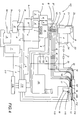
- the aforesaid source of compressed air 116 which feeds compressed air at a first determined pressure, communicates, through a duct 117, with a filter 1', one of whose outlets is connected to an inlet of a three-way solenoid valve 2'.
- This solenoid valve 2' in its normal working condition, lets compressed air flow through the entire system; if, instead, the system experiences a malfunction or an overpressure occurs, or when the operator needs to intervene to perform, for instance, maintenance operations, the solenoid valve 2' unloads the system through its own duct indicated as 2a.
- an outlet 2b of the solenoid valve 2' is open and it dispenses compressed air towards the remaining portions of the system, whereas under critical conditions the solenoid valve 2' interrupts air delivery and lets the system unload.
- the outlet 2b of the solenoid valve 2' is connected to the inlet of a distributor block 3'.
- This distributor 3' presents three outlets, connected as follows:
- the apparatus 101 includes a control element comprising a programmable PLC 118 which commands the entire operating logic assembly and which receives information from sensors to be described further on.
- the signal 1 commands the block 1', the signal 2 the block 2', the signal 6 the solenoid valve 6', the signal 7 the solenoid valve 7' and the signal 8 the group of solenoid valves V, Z, Q.
- PLC 118 Entering as inputs to PLC 118 are signals coming from four sensors indicated respectively as 16, 17, 18 and 20 ( Figure 4). More specifically, as shall be made clearer further on, the sensors 17 and 18 constitute the contact of a switch 115 of the riveting gun 103.
- the sensor 16 is a proximity sensor which detects the position of the front arming device 111: if this position is not correct, the sensor 16 does not intervene, whereas it sends a signal to the PLC 118 only if the position of the front arming device 111 is not correct; if the sensor 16 emits this signal, the supply of rivets 102 to the pistol 103 is shut off, for instance by closing the solenoid valve 7'.
- the sensor 20 is provided in correspondence with the outlet U of the nails 105, to verify that the exit of the nails 105 themselves occurs properly and that the duct U is not obstructed.
- the sensors 17 and 18 are the command sensors associated with the push-button 115 for activating the gun 103.
- each rivet 102 transits inside the duct 12, to the junction area between the duct 12 itself and the duct V1, under the action of a flow of compressed air subjected to a two bar pressure.
Landscapes
- Engineering & Computer Science (AREA)
- Mechanical Engineering (AREA)
- Portable Nailing Machines And Staplers (AREA)
- Insertion Pins And Rivets (AREA)
- Feeding Of Articles To Conveyors (AREA)
Abstract
Description
- Figure 1 shows a side view of the rivet gun to which is associated a rivet feeding apparatus according to the present invention;
- Figure 2 shows, partially in section, a side view of some details of the rivet feeding apparatus as per Figure 1;
- Figure 3 shows a plan view ofthe details in Figure 2;
- Figure 4 shows, in block diagram form, an additional portion of the rivet feeding apparatus as per the previous figures.
- first outlet A': a corresponding pneumatic duct A reaches a block 9' (which
will be discussed further on) and connects to the
aforesaid duct 12 for hurling therivets 102. In particular, duct A exits blocks 3' and enters a block 4', which comprises a reducer or pressure regulating element which reduces the pressure of the compressed air from its value of first determined pressure to a second determined pressure, usually with a relatively modest value (preferably equal to two bar) with respect to the delivery value of the aforesaid source of compressedair 116. The block 4' in turn is connected at its output to the input of a block 7', which comprises a first solenoid valve feeding the aforesaid block 9' in one of its parts destined to hurling therivets 102 through the aforesaid duct 12 (see in particular figure 1). - Second outlet B': a corresponding pneumatic duct B reaches a block 5', which
comprises a second reducer or pressure regulating element whose task is to
reduce the pressure of the air coming from the aforesaid source of compressed
air and which therefore presents the aforesaid first determined pressure, to a
value essentially equal to said second predetermined pressure, equal to two bar.
The block 5' is connected at its output to a block 6', which comprises a
solenoid valve presenting two outlets connected respectively to two ducts B'
and B". The ducts B' and B" are both connected to the
riveting gun 103 and allow, in a way that is known and not described hereafter, the movement of thefront arming device 111 of therivets 102 in order to arm theriveting gun 103 itself. It is deemed sufficient to state that the ducts B' and B" move thearming device 111 of thepistol 103 between the two positions of loading and awaiting therivet 102 which arrives along theaforesaid duct 12. - Third outlet C': a corresponding duct C at high pressure not subjected to
reductions, and thus essentially equal to the aforesaid first determined pressure
supplied by the source of compressed
air 116, essentially equal to six bar, enters a block 8', and feeds three solenoid valves V, Z and Q which comprise said block 8'. In particular, the solenoid valve Q feeds two outgoing ducts Q1 and Q2 that lead to the inlet of a block 10', which contains a hydraulic piston which under the action ofthe air jets coming from the solenoid valve Q moves pressurising some fluid; this fluid, through an outlet duct K, reaches thepistol 103, and specifically it reaches the assembly for drawing and hurling thenail 105 of therivet 102.
- the duct V1, as shall be made clear further on, is devoted to delivering air at
the aforesaid first determined pressure (six bar pressure) to hurl the
rivet 102 in correspondence with a terminal portion of theduct 12, in correspondence with which an end of the duct V1 itself enters the duct 12 (see Figure 1); this duct V1, in conjunction with theduct 12, shall also be defined, hereinafter, with the term "conveying means" for therivets 102; - the duct V2 is the channel that supplies the
gun 103 with the pressure for returning thenail 105 once it has been drawn from therivet 102. The duct V2 connects back within the gun (in a known way) to aduct 22, through which pass the drawn nails 105 (the ones that have been used and no longer have the rivet); theduct 22 is essentially the nail-ejection outlet, and it ends in correspondence with an outlet unit U. Note that, in theapparatus 101, to expel the usednails 105 there is an actual active pressure.
Claims (7)
- Apparatus for feeding rivets for riveting guns, comprising pneumatic conveyor means (12, V1), able to feed the rivets (102) to an arming device (111) of a riveting gun (103), and being connected at least to one source of compressed air (116) supplying the compressed air at a first determined pressure, characterised in that said pneumatic conveyor means (12, V1) comprise a first (12) and a second (V1) duct, said first duct (12) defining the route along which the rivets are destined to travel (102) and being at least provided first pressure regulating means (4') shaped and positioned in such a way as to impose to the air acting along said first duct (12) a second determined pressure; said second duct (V1) presenting an end, opposite to the one connected to said source of compressed air (116), connected to a portion of said first duct (12) positioned in proximity of said arming device (111); said second determined pressure which acts along said first duct (12) being lower than said first determined pressure which acts along said second duct (V1).
- Apparatus according to claim 1, characterised in that it comprises first valve means (7') able to control the flow of the compressed air through said first pressure regulating means (4') and to send it inside said first duct (12) at said second determined pressure; second valve means (V) able to control the flow of compressed air coming from said source of compressed air (116) and to send it inside said second duct (V1) at said first determined pressure; said second valve means (V) also being able to control the flow of compressed air coming from said source of compressed air and to send it inside a third duct (V2) which in turn feeds a duct (22) for ejecting the nails (105) once they have been used inside the riveting gun (103) to drive the rivets (102), so that in said ejection duct an active pressure for hurling the nails (105) themselves is present and operating.
- Apparatus according to claim 1, characterised in that it comprises third (B') and fourth (B") ducts able to move the arming device (111) of said rivets (102); second pressure regulating means (5') being provided, positioned and shaped in such a way as to impart to the air acting along said third and fourth ducts (B', B") said second determined pressure and third valve means (6') able to control the flow of the compressed air through said second pressure regulating means (5').
- Apparatus according to one of the previous claims from 1 through 3, characterised in that it comprises governing means (118) to control the operation of said first, second and third valve means (7', V, 6').
- Apparatus according to one of the previous claims from 1 to 4, characterised in that said first and second pressure regulating means comprise pressure reducers (4', 5').
- Apparatus according to claim 1, characterised in that said first pressure regulating means (4') are able to impart to the compressed air which flows along said first duct (12) a pressure essentially equal to two bar.
- Apparatus according to claim 3, characterised in that said second pressure regulating means (5') are able to impart to the compressed air transiting along said third and fourth ducts (B', B"), a pressure essentially equal to two bar.
Applications Claiming Priority (2)
| Application Number | Priority Date | Filing Date | Title |
|---|---|---|---|
| ITBO960470 | 1996-09-20 | ||
| IT96BO000470A IT1286228B1 (en) | 1996-09-20 | 1996-09-20 | RIVET FEEDING EQUIPMENT FOR RIVETING PISTOLS |
Publications (2)
| Publication Number | Publication Date |
|---|---|
| EP0830909A2 true EP0830909A2 (en) | 1998-03-25 |
| EP0830909A3 EP0830909A3 (en) | 1999-12-15 |
Family
ID=11341604
Family Applications (1)
| Application Number | Title | Priority Date | Filing Date |
|---|---|---|---|
| EP97830449A Withdrawn EP0830909A3 (en) | 1996-09-20 | 1997-09-15 | Apparatus for feeding rivets for riveting guns |
Country Status (3)
| Country | Link |
|---|---|
| US (1) | US6000596A (en) |
| EP (1) | EP0830909A3 (en) |
| IT (1) | IT1286228B1 (en) |
Families Citing this family (6)
| Publication number | Priority date | Publication date | Assignee | Title |
|---|---|---|---|---|
| GB9903148D0 (en) * | 1999-02-12 | 1999-04-07 | Henrob Ltd | Fastener delivery apparatus |
| US6854178B2 (en) * | 2002-04-02 | 2005-02-15 | The Boeing Company | Through-the-drill plate fastener installation tool |
| GB0518696D0 (en) * | 2005-09-14 | 2005-10-19 | Henrob Ltd | Fastener feed method and apparatus |
| US8046898B2 (en) * | 2005-10-18 | 2011-11-01 | The Boeing Company | Fastener clearing systems and methods |
| US8805575B1 (en) * | 2011-07-11 | 2014-08-12 | The Boeing Company | Methods and apparatus for delivering fasteners |
| US10022782B1 (en) | 2017-01-13 | 2018-07-17 | Milawukee Electric Tool Corporation | Attachment for a rivet setting tool |
Citations (5)
| Publication number | Priority date | Publication date | Assignee | Title |
|---|---|---|---|---|
| US4027520A (en) * | 1974-08-30 | 1977-06-07 | Gesipa Blindniettechnik Gesellschaft Mit Beschrankter Haftung | Blind riveter with automatic rivet feed |
| GB2180482A (en) * | 1985-09-19 | 1987-04-01 | Avdel Ltd | Apparatus for installing rivets |
| US4811881A (en) * | 1987-11-20 | 1989-03-14 | Phillips Plastics Corporation | Apparatus for supplying and installing plastic expansion rivets |
| EP0350370A1 (en) * | 1988-07-05 | 1990-01-10 | SOCIETE INDUSTRIELLE DE MECANIQUE ET D'AUTOMATION DU FAUCIGNY dite S.I.M.A.F.(Société Anonyme) | Automatic tool for placing inserts, especially of the bushing type |
| US4901431A (en) * | 1988-06-06 | 1990-02-20 | Textron Inc. | Powered fastener installation apparatus |
Family Cites Families (8)
| Publication number | Priority date | Publication date | Assignee | Title |
|---|---|---|---|---|
| US1980967A (en) * | 1930-11-22 | 1934-11-13 | Cleveland Pneumatic Tool Co | Nail driving device |
| SE308867B (en) * | 1966-05-26 | 1969-02-24 | Dahlberg Ab F | |
| US3906615A (en) * | 1973-09-19 | 1975-09-23 | Automated Manufacturing System | Method for feeding and driving tacks |
| US4720215A (en) * | 1984-10-31 | 1988-01-19 | Grumman Aerospace Corporation | Rivet delivery system |
| GB8608817D0 (en) * | 1986-04-11 | 1986-05-14 | Advel Ltd | Fastener installation apparatus |
| US5014876A (en) * | 1988-10-20 | 1991-05-14 | Design Tool, Inc. | Fastener feed assembly |
| GB2267451A (en) * | 1992-05-15 | 1993-12-08 | Avdel Systems Ltd | Riveting tool |
| IT1279972B1 (en) * | 1995-06-30 | 1997-12-23 | Far Srl | FEEDING, TILTING AND FRONT LOADING EQUIPMENT OF RIVETS FOR RIVETING PISTOLS |
-
1996
- 1996-09-20 IT IT96BO000470A patent/IT1286228B1/en active IP Right Grant
-
1997
- 1997-09-15 EP EP97830449A patent/EP0830909A3/en not_active Withdrawn
- 1997-09-16 US US08/931,690 patent/US6000596A/en not_active Expired - Fee Related
Patent Citations (5)
| Publication number | Priority date | Publication date | Assignee | Title |
|---|---|---|---|---|
| US4027520A (en) * | 1974-08-30 | 1977-06-07 | Gesipa Blindniettechnik Gesellschaft Mit Beschrankter Haftung | Blind riveter with automatic rivet feed |
| GB2180482A (en) * | 1985-09-19 | 1987-04-01 | Avdel Ltd | Apparatus for installing rivets |
| US4811881A (en) * | 1987-11-20 | 1989-03-14 | Phillips Plastics Corporation | Apparatus for supplying and installing plastic expansion rivets |
| US4901431A (en) * | 1988-06-06 | 1990-02-20 | Textron Inc. | Powered fastener installation apparatus |
| EP0350370A1 (en) * | 1988-07-05 | 1990-01-10 | SOCIETE INDUSTRIELLE DE MECANIQUE ET D'AUTOMATION DU FAUCIGNY dite S.I.M.A.F.(Société Anonyme) | Automatic tool for placing inserts, especially of the bushing type |
Also Published As
| Publication number | Publication date |
|---|---|
| ITBO960470A0 (en) | 1996-09-20 |
| IT1286228B1 (en) | 1998-07-08 |
| ITBO960470A1 (en) | 1998-03-20 |
| EP0830909A3 (en) | 1999-12-15 |
| US6000596A (en) | 1999-12-14 |
Similar Documents
| Publication | Publication Date | Title |
|---|---|---|
| US5480087A (en) | Fastener feeding apparatus | |
| US8973247B2 (en) | Method and device for supply of connecting elements to a processing apparatus | |
| US8517432B2 (en) | Sand dosing and blocking device | |
| US4208153A (en) | Apparatus for dispensing rivets and similar articles | |
| CA2504752C (en) | Apparatus and method for making a fine oil mist | |
| US6000596A (en) | Apparatus for feeding rivets for riveting guns | |
| US4275976A (en) | Pneumatic conveyor system | |
| AU5183599A (en) | Improvements in or relating to fastening machines | |
| US20080279641A1 (en) | Fluidification device for granular material | |
| GB1148839A (en) | Pneumatic conveying system for cigarette-making machines | |
| US3437384A (en) | Conveying system and valve constructions therefor | |
| US3185277A (en) | Pneumatic divider and distributor | |
| TR199801836T2 (en) | Method and device for automatic and uninterrupted pneumatic feeding of tobacco. | |
| US4014577A (en) | Pneumatic conveying systems | |
| US5289899A (en) | Apparatus and method for lubricating conveyors | |
| US20100014926A1 (en) | System and Method for Pneumatically conveying Metered Amounts of Bulk Particulate Material | |
| US4883078A (en) | Transport system for transporting rod-shaped objects in an air flow | |
| US5049008A (en) | Air pulse discharge control valve for fluidizing dry particulate material | |
| CN116583378A (en) | Preseparation device, joining apparatus and method for operating a joining apparatus | |
| JP2006199439A (en) | Chute blockage preventive device of long-distance conveyor | |
| KR20170116668A (en) | Pneumatic material conveying system | |
| US2784928A (en) | Snow blower control systems | |
| US20230363398A1 (en) | Intelligent Lubricating Method and Device | |
| US2793084A (en) | Apparatus for storing and transporting powdered material | |
| SU982871A1 (en) | Automatic line transportation system |
Legal Events
| Date | Code | Title | Description |
|---|---|---|---|
| PUAI | Public reference made under article 153(3) epc to a published international application that has entered the european phase |
Free format text: ORIGINAL CODE: 0009012 |
|
| AK | Designated contracting states |
Kind code of ref document: A2 Designated state(s): BE DE ES FR GB IT NL |
|
| AX | Request for extension of the european patent |
Free format text: AL;LT;LV;RO;SI |
|
| PUAL | Search report despatched |
Free format text: ORIGINAL CODE: 0009013 |
|
| AK | Designated contracting states |
Kind code of ref document: A3 Designated state(s): AT BE CH DE DK ES FI FR GB GR IE IT LI LU MC NL PT SE |
|
| AX | Request for extension of the european patent |
Free format text: AL;LT;LV;RO;SI |
|
| AKX | Designation fees paid |
Free format text: BE DE ES FR GB IT NL |
|
| STAA | Information on the status of an ep patent application or granted ep patent |
Free format text: STATUS: THE APPLICATION IS DEEMED TO BE WITHDRAWN |
|
| 18D | Application deemed to be withdrawn |
Effective date: 20041001 |