EP0830901A2 - Verriegelungseinrichtung für ein Lacksystem - Google Patents
Verriegelungseinrichtung für ein Lacksystem Download PDFInfo
- Publication number
- EP0830901A2 EP0830901A2 EP97306732A EP97306732A EP0830901A2 EP 0830901 A2 EP0830901 A2 EP 0830901A2 EP 97306732 A EP97306732 A EP 97306732A EP 97306732 A EP97306732 A EP 97306732A EP 0830901 A2 EP0830901 A2 EP 0830901A2
- Authority
- EP
- European Patent Office
- Prior art keywords
- lid
- handle
- paint
- bag
- latch
- Prior art date
- Legal status (The legal status is an assumption and is not a legal conclusion. Google has not performed a legal analysis and makes no representation as to the accuracy of the status listed.)
- Withdrawn
Links
Images


Classifications
-
- B—PERFORMING OPERATIONS; TRANSPORTING
- B65—CONVEYING; PACKING; STORING; HANDLING THIN OR FILAMENTARY MATERIAL
- B65D—CONTAINERS FOR STORAGE OR TRANSPORT OF ARTICLES OR MATERIALS, e.g. BAGS, BARRELS, BOTTLES, BOXES, CANS, CARTONS, CRATES, DRUMS, JARS, TANKS, HOPPERS, FORWARDING CONTAINERS; ACCESSORIES, CLOSURES, OR FITTINGS THEREFOR; PACKAGING ELEMENTS; PACKAGES
- B65D75/00—Packages comprising articles or materials partially or wholly enclosed in strips, sheets, blanks, tubes or webs of flexible sheet material, e.g. in folded wrappers
- B65D75/52—Details
- B65D75/58—Opening or contents-removing devices added or incorporated during package manufacture
- B65D75/5861—Spouts
- B65D75/5872—Non-integral spouts
- B65D75/5883—Non-integral spouts connected to the package at the sealed junction of two package walls
-
- B—PERFORMING OPERATIONS; TRANSPORTING
- B05—SPRAYING OR ATOMISING IN GENERAL; APPLYING FLUENT MATERIALS TO SURFACES, IN GENERAL
- B05C—APPARATUS FOR APPLYING FLUENT MATERIALS TO SURFACES, IN GENERAL
- B05C17/00—Hand tools or apparatus using hand held tools, for applying liquids or other fluent materials to, for spreading applied liquids or other fluent materials on, or for partially removing applied liquids or other fluent materials from, surfaces
- B05C17/002—Hand tools or apparatus using hand held tools, for applying liquids or other fluent materials to, for spreading applied liquids or other fluent materials on, or for partially removing applied liquids or other fluent materials from, surfaces with feed system for supplying material from an external source; Supply controls therefor
-
- B—PERFORMING OPERATIONS; TRANSPORTING
- B05—SPRAYING OR ATOMISING IN GENERAL; APPLYING FLUENT MATERIALS TO SURFACES, IN GENERAL
- B05C—APPARATUS FOR APPLYING FLUENT MATERIALS TO SURFACES, IN GENERAL
- B05C17/00—Hand tools or apparatus using hand held tools, for applying liquids or other fluent materials to, for spreading applied liquids or other fluent materials on, or for partially removing applied liquids or other fluent materials from, surfaces
- B05C17/02—Rollers ; Hand tools comprising coating rollers or coating endless belts
- B05C17/03—Rollers ; Hand tools comprising coating rollers or coating endless belts with feed system for supplying material from an external source or with a reservoir or container for liquid or other fluent material located in or on the hand tool outside the coating roller
- B05C17/0316—Rollers ; Hand tools comprising coating rollers or coating endless belts with feed system for supplying material from an external source or with a reservoir or container for liquid or other fluent material located in or on the hand tool outside the coating roller with pressurised or compressible container
-
- B—PERFORMING OPERATIONS; TRANSPORTING
- B05—SPRAYING OR ATOMISING IN GENERAL; APPLYING FLUENT MATERIALS TO SURFACES, IN GENERAL
- B05C—APPARATUS FOR APPLYING FLUENT MATERIALS TO SURFACES, IN GENERAL
- B05C17/00—Hand tools or apparatus using hand held tools, for applying liquids or other fluent materials to, for spreading applied liquids or other fluent materials on, or for partially removing applied liquids or other fluent materials from, surfaces
- B05C17/02—Rollers ; Hand tools comprising coating rollers or coating endless belts
- B05C17/03—Rollers ; Hand tools comprising coating rollers or coating endless belts with feed system for supplying material from an external source or with a reservoir or container for liquid or other fluent material located in or on the hand tool outside the coating roller
- B05C17/035—Rollers ; Hand tools comprising coating rollers or coating endless belts with feed system for supplying material from an external source or with a reservoir or container for liquid or other fluent material located in or on the hand tool outside the coating roller direct or indirectly to the outer surface of the coating roller
-
- B—PERFORMING OPERATIONS; TRANSPORTING
- B65—CONVEYING; PACKING; STORING; HANDLING THIN OR FILAMENTARY MATERIAL
- B65D—CONTAINERS FOR STORAGE OR TRANSPORT OF ARTICLES OR MATERIALS, e.g. BAGS, BARRELS, BOTTLES, BOXES, CANS, CARTONS, CRATES, DRUMS, JARS, TANKS, HOPPERS, FORWARDING CONTAINERS; ACCESSORIES, CLOSURES, OR FITTINGS THEREFOR; PACKAGING ELEMENTS; PACKAGES
- B65D2231/00—Means for facilitating the complete expelling of the contents
- B65D2231/001—Means for facilitating the complete expelling of the contents the container being a bag
- B65D2231/002—Means for facilitating the complete expelling of the contents the container being a bag comprising strips forming channels or liquid passageways
-
- B—PERFORMING OPERATIONS; TRANSPORTING
- B65—CONVEYING; PACKING; STORING; HANDLING THIN OR FILAMENTARY MATERIAL
- B65D—CONTAINERS FOR STORAGE OR TRANSPORT OF ARTICLES OR MATERIALS, e.g. BAGS, BARRELS, BOTTLES, BOXES, CANS, CARTONS, CRATES, DRUMS, JARS, TANKS, HOPPERS, FORWARDING CONTAINERS; ACCESSORIES, CLOSURES, OR FITTINGS THEREFOR; PACKAGING ELEMENTS; PACKAGES
- B65D2401/00—Tamper-indicating means
- B65D2401/15—Tearable part of the closure
-
- B—PERFORMING OPERATIONS; TRANSPORTING
- B65—CONVEYING; PACKING; STORING; HANDLING THIN OR FILAMENTARY MATERIAL
- B65D—CONTAINERS FOR STORAGE OR TRANSPORT OF ARTICLES OR MATERIALS, e.g. BAGS, BARRELS, BOTTLES, BOXES, CANS, CARTONS, CRATES, DRUMS, JARS, TANKS, HOPPERS, FORWARDING CONTAINERS; ACCESSORIES, CLOSURES, OR FITTINGS THEREFOR; PACKAGING ELEMENTS; PACKAGES
- B65D2575/00—Packages comprising articles or materials partially or wholly enclosed in strips, sheets, blanks, tubes or webs of flexible sheet material, e.g. in folded wrappers
- B65D2575/52—Details
- B65D2575/58—Opening or contents-removing devices added or incorporated during package manufacture
- B65D2575/583—Opening or contents-removing devices added or incorporated during package manufacture the non-integral spout having an elongate cross-sectional shape, e.g. canoe or boat shaped
Definitions
- This invention relates to a paint system of the type broadly disclosed in GB 2142386.
- paint may be supplied to customers in flexible paint reservoirs, or bags.
- a machine is supplied which contains a bellows, or other pressurising means, arranged to squeeze the bag of paint and force the paint to exit the bag through a tube to a paint dispensing element, such as a brush or roller.
- the present invention is particularly concerned with a system of the type comprising:-
- a paint system comprising:-
- the latch is part of a handle pivoted to the container and pivotable between open and closed positions thereof, the latch being active in the closed position of the handle.
- said lid is pivoted to the container and second lid means holds the handle in its closed position when the lid is in its closed position.
- the second lid means may comprise a catch on the lid which is caught by the handle on closing of the handle when the lid is already closed.
- said lid means comprises the bellows serving to move the handle to its open, inactive position when the lid is open and the pump is operated to pressurise the bellows.
- Said lid means may comprise a connection between the bellows and lid which, when the lid is open and the pump is operated, serves to pivot the lid, which then contacts the handle to move the handle to its open, inactive position.
- said latch comprises at least one substantially C-shaped clasp on the handle, ends of the clasp being adapted to engage ledges on the lid and container when the handle is closed after the lid is closed.
- the switch comprises a switch body and a switch actuator, the body being movable relative to the container between first and second positions, in the first position of which, said switch actuator is actuatable by the user and in the second position of which said switch actuator is not actuatable by the user, the latch means being operable to move the body and maintain it in said first position when the latch is active.
- the switch further comprises a user operable button adapted either to actuate the switch actuator when said arm is in said first position and when said latch is active, or serving to move the arm to said second position when the latch is not active.
- the latch means comprises part of the handle which, when the handle is closed, moves the switch body to its first position.
- a paint system that incorporates the concepts of the present invention has numerous advantages. This is not to say that it would be impossible to operate the system incorrectly; for example, there is no provision by the arrangements described herein that prevent operation of the system without the tube connected to the system at all. In such a situation it would be entirely possible for the user to operate the system, and make an horrendous mess in the process!
- to provide arrangements which prevent such "accidents" involves additional complexity and expense and is unnecessary for normal operation.
- Closure of the handle serves to enable actuation of the machine, but unless the lid is closed, the handle does not stay closed, not only because there is nothing to keep it closed, but also because inflation of the bellows tends to pull the lid towards its closed position which would press against the handle to open it.
- inflation of the bellows tends to pull the lid towards its closed position which would press against the handle to open it.
- paint is used exclusively herein, it should be understood to include any liquid, and, indeed, while the invention is described exclusively in relation to the application of paint, which in this context includes other surface coating compositions such as varnishes, stains and lacquers, the concepts embodied in the present invention may be employed in the dispensing of liquids completely unrelated to surface coating compositions.
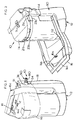
- a paint system according to the present invention comprises a paint machine 10 having a main container body 12, a lid 14 and a handle arrangement 16.
- a back cover 18 is shown in Figure 1, but is removed from Figure 2.
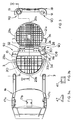
- Container 12 defines a large open internal volume 20 having a top edge 9 and being adapted to receive a bellows 22 and a paint bag 24.
- the bellows is pressurised with air through a tube 26 entering the bottom of the bellows by a pump unit 28 disposed in a space between the back of the container 12 and back cover 18.
- the pump unit 28 is operated by a button 30 and is powered by a battery (not shown).
- the paint bag 24, when filled with paint, is placed in the container 12 where it nestles close to the bellows 22, and fits snugly inside the volume 20.
- the lid 14 is pivoted to the container about axis 32 to close the container 12.
- the paint bag has an opening 40 (see Figure 9) to which a connector 50 can be fitted.
- the connector 50 is at one end of a flexible tube 60 ( Figures 14a to c) leading at its other end to a handle 70 ( Figure 15) to which a paint applicator such as roller arrangement 80 ( Figures 16a and b) may be attached.
- This is also schematically shown in Figure 6.
- the container top edge and lid have respective recesses 34,36 adapted to receive the connector 50 when correctly oriented as explained further below.
- Handle 16 is pivoted to the container about axis 3. When the lid is closed, handle 16 can be pivoted to the position shown in Figure 1 where it prevents the lid from opening, by means more explicitly described below.
- the lid includes a catch 7, pivoted to the lid about axis 5 and biased by spring 11 toward engagement with an eye 16a in the top of handle arrangement 16. Catch 7, when engaged with eye 16a, (which, of course, can only happen when the lid is first closed and the handle closed second) keeps the handle in its closed position.
- the pump unit 28 pressurises bellows 22 which expand and compress the paint bag 24. Paint in the bag is then squeezed out through opening 40 into tube 60, and thence to handle 70 and applicator 80.
- a control knob 72 on handle 70 is used to control flow of paint to roller arrangement 80 so that sufficient is supplied to maintain the requisite wetness of the roller as it is rolled over a wall or other surface to which paint is to be applied.
- compositions in this regard have a high viscosity, and various other characteristics, when compared, for example, with water.
- a copending application filed by the present applicants contemporaneously with the present application under the title "Process for the roller-application of an aqueous thixotropic paint at ambient temperatures" describes a formulation particularly adapted for the system of the present invention. To gain sufficient flow of such paint to the roller, in order to achieve a reasonable rate of surface coverage, either the diameter of the tube should be large, or the pressure developed by the machine should be large.
- container 12 has substantial latticing on its flat surfaces, that is to say along its back surface 13 and bottom 15, in order to provide reinforcement of those surfaces.
- the lid 14 is likewise latticed. Curved surfaces of the container do not require such reinforcement.
- the lid 14 is retained in place by the handle 16 in which metal clips, or clasps 17, (see insets to Figure 3 which show the clips in side view (a) and front view (b), and also Figure 5b) are connected.
- the clips are fitted in the handle at positions 17a, b and c, and edges 47 thereof are adapted to form a latch and to capture lips, or ledges, 21a, b and c and 23a, b and c on the lid and container respectively.
- the handle itself does not itself require the strength to withstand the opening forces imposed on the lid as the bellows inflate and expand; rather it is the latches 17 which accommodate such forces and keep the lid closed.
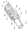
- the container 12 and back cover 18 define between them two wings 90,92, in one of which (90) is disposed the pump unit 28, its button 30 protruding through aperture 91 in back cover 18, and in the other (92) is disposed a removable and rechargeable battery (not shown), which powers the pump unit, and which is accessible through aperture 19 in back cover 18.
- FIG 8 illustrates the pump unit 28, which comprises a frame 94 mounting a small electric motor 96.
- the motor drives an eccentric link 98 so that a piston 100 connected to a diaphragm (not shown) is caused to rotate. Air is drawn into a diaphragm chamber on one stroke of the piston and pressured into a pressure chamber on the other stroke. Air exits the pressure chamber through outlet 102 to which tube 26 is connected.
- the pressure chamber is controlled by an actuator 104 which lifts when the pressure reaches a predetermined value.
- the pressure chamber is also controlled by a separate yield/dump valve. None of these components are shown or described in detail because they are not directly relevant to the present invention.
- Button 30 when depressed, actuates microswitch 106 mounted on one end of a swing arm 108, which is pivoted about hinge 110 at its other end to the frame 94. However, even when the button is depressed, microswitch 106 is not actuated unless swing arm 108 is pivoted downwardly in Figure 8. This occurs when handle 16 is moved to its closed position and pip 112 enters window 114 on the front side of wing 90 and presses against a leaf spring element 116 (see Figure 4b) which hangs, pivotably about axis 117, from the back of the front side of wing 90. Spring element 116 in turn presses swing arm 108, with a small spring force, against yield actuator 104.
- pip 112, and element 116, between them constitute latch means to prevent operation of the motor until the latch, constituted by the handle 16 and its clasps 17, is active, i.e. engaged to latch the lid 14 closed.
- latch and the latch means are separate entities, but are connected so as to operate simultaneously.
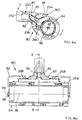
- Lid 14 is in fact arranged to be capable of opening only as far as shown in Figure 5 (and not as far as shown, for the sake of clarity, in Figure 3).
- the bellows 22 has two flaps at its top, one of which 25 is connected to the top of back 13 of the container, while the other larger flap 27 is connected to the middle of the underside of lid 14.
- the paint bag 24 comprises a plastics envelope welded around its periphery.
- a gusset 24a is folded under and forms a base of the bag 24.
- a carrying handle 120 is formed in one corner, and in the other is the opening 40.
- the opening 40 comprises a discrete opening element 41 captured by the bag envelope and welded to it.
- Element 41 comprises a weld part, or base, 122 having tapering lead-in, lead-out regions 124,126 enabling reliable welding to the bag envelope.
- Behind the weld part is connected a dip element 128 which serves to keep the walls of the envelope apart and ensure a passage for paint in the bag from the bottom of the bag to the opening.
- a passage 130 is formed through the weld part and into a neck 132 of the element 41.
- the dip element 128 is essentially cruciform in section and connects with the weld part at two points 134 providing access to the bag interior from the passage 130.
- Neck 132 has, from its connection to the weld part 122, a flange 136, a screw threaded region 138, a bayonet region 140, and a mouth 142 for the passage 130.
- Flange 136 has two equi-spaced detents, or notches, 144. The flange captures a security ring 147 on a sealing cap 145 ( Figure 12).
- Cap 145 is internally screw threaded for engagement with screw thread 138 on the neck 132 of the opening.
- a seal flange 149 is adapted to seal against, and close, mouth 142.
- tags 151 (connecting the ring 147 to the rest of the cap) break and leave the ring 147 in place behind flange 136 (see Figure 10b).
- Bayonet 140 of the neck 132 comprises merely a one third- to one half- turn screw thread 141, one on either side of the neck.
- Connector 50 comprises two discrete elements, a main connector body 150 and a connection element 152.
- Connector body 150 has a connection region 154, a flexible region 156, a support region 158 and a protection region 160.
- the tube 60 passes through the connector body and is press fitted over one end 162 of connection element 152.
- a circumferential rib 164 aids sealing and also ensures a tight fit when the connector body is slid over the tube and snapped into engagement with the element 152, a ring flange 166 on the element snapping under barbs 168 in the body 150.
- a sleeve 170 of the body closely surrounds the end 162 of the element 152 and presses the tube into engagement with the rib 164 securing the connection of the tube to the element 152.
- connection region of the connector 150 is the flexible region 156.
- the reason for this flexible region is explained further below, but it comprises an helical formation 172 which gives the region flexibility but at the same time a certain amount of rotational rigidity, at least in one, tightening direction of rotation of the helix, about the long axis of the connector.
- the support region 158 which, in Figures 10b and 10c is shown in two alternative forms, cross sections of each form being shown in Figures 13a and 13b respectively.
- the Figure 10b embodiment is preferred and, apart from comprising a rigid sleeve 174 which both embodiments employ, it has two opposed depending pillars 176, one of which is adapted to be received in an eye 35 formed in the base of recess 34 of the container 12.
- the support region is given a rectangular section adapted to be received in the recess 34 which would be correspondingly shaped and so as to ensure only two possible orientations of the connector in the recess.
- the protection region 160 extends from the support region 174 and may, like the flexible region comprise a helix, or as shown may comprise a lattice type arrangement, in either case merely to ensure that the tube exiting the support region cannot kink through a small angle but is supported over a larger radius of bend by the protection region 160.
- the flexible region 156 may also be arranged as a lattice formation, but helix is preferred for both since a helix provides greater flexibility.
- connection element 152 has a smooth external circular cross-section 153 over a similar length from its own mouth 178. Near its mouth, the connection element 152 has a circumferential groove in which is disposed an elastomeric O-ring 155, adapted to provide a seal against passage 130 when the connector 150 is engaged with bag opening 40.
- connection element 152 the connector body 150 in its connection region 154 has a pair of bayonet dogs 180 (see also Figure 11). These are adapted to be engaged in entries 143 of bayonet screw thread 141 of neck 132.
- dogs 180 are engaged with thread 141 and the connector is turned through about 90 degrees, two lugs 182 on the inside of a collar 183 of the connection region 154 engage flange 136 on neck 132 of the bag opening 40.
- the lugs snap into detent notches 144 in the flange 136.
- FIG 14 this illustrates the process of bag 24 emptying of paint during use as the bellows 22 expand.
- the lid 14 is shown open and, for the reasons explained above, this cannot, in fact, be the case while the machine 10 operates.
- the lid is shown open for the sake of clarity.
- the flap 27 of the bellows appears to grow in Figures 14a, b and c, but of course this is not, in reality, the case, although the flap does move during bellows inflation under its connection to the lid when the lid is closed.
- the bellows 22 When the machine is switched on, the bellows 22 begins to inflate and squeeze the bag 24 in the container 12 so that paint therein exits through bag opening 40, through connector 50 into tube 60, and thence to handle 70 and paint applicator 80 (described further below) for application to a surface such as a wall.
- the length of the overlapping circular section parts 130, 153 of the opening and connector respectively is at least as great as the diameter of such parts. This ensures that flexing which takes place in the connector as described above does not result in leakage around the seal.
- the O-ring 155 is placed near the mouth 178 of the connection element 152 so that the seal line is deep within the throat of passage 130 so that when the parts are disconnected, drips are less likely to occur, and cleaning of the connector after use is easier. The latter arises because paint does not go around the outside of surface 153 very far before it meets the seal line formed by the O-ring 155. It should however be mentioned that surface 153 quite clearly does not have to be circular cylindrical to perform adequately; it could be hexagonal, for example, in section, as long as there was sufficient resilience in the O-ring to achieve a complete seal.
- the bellows 22 is a double envelope comprising front and back sheets 190,192 of elastomeric material, preferably coated in woven cotton to aid slippage against the plastics material of the bag 24, with upper and lower gussets 194,196. Between lower gusset 196 and back sheet 192, an opening 198 is formed for connection of air tube 26. Flap 27 is an extension of front sheet 190, while flap 25 is an extension of back sheet 192 (or the gusset 194). The gussets 194,196 are connected internally of the bellows by elastic elements 200.
- the tube 60 at its end remote from the connector 50 is connected by a screwed adaptor 209 to an input element 210 of handle 70.
- handle 70 has an output 220 having a sleeve element 222 with a circumferential groove to receive an elastomeric O-ring 223.
- Output 220 has a tapering mouth 224 to receive correspondingly tapering input 250 to applicator 80.
- the O-ring is adapted to seal against circular cylindrical surface 252 of input 250.
- handle 70 Between its input and output, handle 70 comprises a body 230 including a resiliently elastic tube element 232. Tube element 232 passes over an anvil 234 formed in the body. Above the anvil and tube element is the head 236 of a squeeze lever 238, which head is pressed against anvil 234, squeezing and sealing the tube element 232 therebetween, by a spring 240, mounted in the body 230. Squeeze lever 238 is pivoted in the body about axis 242, and its other end 244 is actuated by switch lever 246, also pivoted in the body about axis 248. Switch lever 246 has knob 72 which extends through an opening 214 in the body 230, and which knob is actuable by the user.
- the handle is therefore a deadman's handle, the spring 240 serving to close flow of paint in the tube element 232 and through the handle 70 until the knob 72 is pressed by the user. Pressing the knob 72 pivots the switch lever, clockwise in Figure 15, about axis 248, which in turn pivots squeeze lever 238 anti-clockwise about axis 242. Such pivoting is against the restoring force of spring 240, but opens tube element 232 to permit flow of paint while the knob is pressed.
- the lever arrangement is such that only a small movement of head 236 results from a large movement of the knob 72. This is desirable on two counts. Firstly the spring 240 needs to be quite strong to ensure adequate sealing under the working pressure when the knob 72 is released, so the extra leverage provided by the arrangement minimises user fatigue.
- the handle 70 which controls paint flow, and therefore indirectly controls operation of the motor 96 of the pump unit 28 in the machine 10. This is because, when the button 30 is activated and the motor 96 starts, the bellows inflates commencing pressurisation of the paint bag.
- applicator 80 here comprises a roller arrangement. Any currently available roller arrangement could be employed, and so also could various brush arrangements which exist. However, the present roller arrangement 80 has several advantages. It comprises a body 82 mounting a roller 84 which is journalled for free rotation about its long axis 86 in the body 82. The roller 84 has pips 88 at its ends which rotate in eyes 89 in body 82.
- a petal 87 has a central sleeve 85 which is a close sliding fit in a bore 83 formed in the body 82 and communicating with input 252.
- the petal is substantially rectangular having a rectangular lip 254 (having curved short ends to correspond with the circumference of the roller 84) adapted to lie against the roller surface.
- the lip 254, the petal inside the lip, and the surface of the roller bounded by the lip, between them define a paint plenum 256 into which paint is supplied from handle 70 when its is connected to applicator 80.
- the petal 87 is biased towards the roller by two leaf springs 258 disposed in the body 82.
- the facing surfaces 83,85 permit the petal to slide in and out slightly to maintain contact of the lip 254 with the roller as it changes diameter with wear or degree of paint loading.
- the petal has two waves 260 outside the long sides of the lip 254. These are adapted to capture paint on the surface of the roller as the roller feeds under the leading lip 254, depending on the direction of roll of the roller, and to feed such paint back into the plenum 256.
Landscapes
- Engineering & Computer Science (AREA)
- Mechanical Engineering (AREA)
- Coating Apparatus (AREA)
- Containers And Packaging Bodies Having A Special Means To Remove Contents (AREA)
Applications Claiming Priority (2)
| Application Number | Priority Date | Filing Date | Title |
|---|---|---|---|
| GB9618713 | 1996-09-07 | ||
| GB9618713A GB2309266B (en) | 1996-09-07 | 1996-09-07 | Paint system interlock |
Publications (2)
| Publication Number | Publication Date |
|---|---|
| EP0830901A2 true EP0830901A2 (de) | 1998-03-25 |
| EP0830901A3 EP0830901A3 (de) | 1998-10-21 |
Family
ID=10799586
Family Applications (1)
| Application Number | Title | Priority Date | Filing Date |
|---|---|---|---|
| EP97306732A Withdrawn EP0830901A3 (de) | 1996-09-07 | 1997-09-02 | Verriegelungseinrichtung für ein Lacksystem |
Country Status (2)
| Country | Link |
|---|---|
| EP (1) | EP0830901A3 (de) |
| GB (1) | GB2309266B (de) |
Cited By (2)
| Publication number | Priority date | Publication date | Assignee | Title |
|---|---|---|---|---|
| DE202008009591U1 (de) * | 2008-07-04 | 2009-11-19 | Advisan Dr. Missel Gmbh | Fungizidauftragvorrichtung |
| EP3028768A1 (de) * | 2014-12-03 | 2016-06-08 | Nirlat Ltd | Gemäldevorrichtung mit einem Airbag |
Citations (1)
| Publication number | Priority date | Publication date | Assignee | Title |
|---|---|---|---|---|
| GB2142386A (en) | 1983-06-27 | 1985-01-16 | Kr Ass Inc | Force driven fluid coating applicator for paint and the like |
Family Cites Families (6)
| Publication number | Priority date | Publication date | Assignee | Title |
|---|---|---|---|---|
| US3933415A (en) * | 1973-05-11 | 1976-01-20 | Woolpert John C | Painting system |
| GB2100357A (en) * | 1981-06-17 | 1982-12-22 | Gen Foods Ltd | Dispenser for a liquid |
| DE3705741A1 (de) * | 1987-02-23 | 1988-09-01 | Hilti Ag | Abgabevorrichtung fuer fliessfaehige massen |
| US5048724A (en) * | 1988-11-22 | 1991-09-17 | Fedpak Systems, Inc. | Soft serve frozen confection dispenser |
| US5368195A (en) * | 1993-05-13 | 1994-11-29 | Pleet; Lawrence | Pressurized bag-in-bottle liquid dispensing system |
| WO1997025156A1 (en) * | 1996-01-11 | 1997-07-17 | Imperial Chemical Industries Plc | Process for the roller-application of an aqueous thixotropic coating composition at ambient temperatures and a combination for use in the process |
-
1996
- 1996-09-07 GB GB9618713A patent/GB2309266B/en not_active Expired - Fee Related
-
1997
- 1997-09-02 EP EP97306732A patent/EP0830901A3/de not_active Withdrawn
Patent Citations (1)
| Publication number | Priority date | Publication date | Assignee | Title |
|---|---|---|---|---|
| GB2142386A (en) | 1983-06-27 | 1985-01-16 | Kr Ass Inc | Force driven fluid coating applicator for paint and the like |
Cited By (3)
| Publication number | Priority date | Publication date | Assignee | Title |
|---|---|---|---|---|
| DE202008009591U1 (de) * | 2008-07-04 | 2009-11-19 | Advisan Dr. Missel Gmbh | Fungizidauftragvorrichtung |
| EP3028768A1 (de) * | 2014-12-03 | 2016-06-08 | Nirlat Ltd | Gemäldevorrichtung mit einem Airbag |
| US9475084B2 (en) | 2014-12-03 | 2016-10-25 | Nirlat Ltd | Painting apparatus comprising an air bag |
Also Published As
| Publication number | Publication date |
|---|---|
| GB9618713D0 (en) | 1996-10-16 |
| GB2309266A (en) | 1997-07-23 |
| EP0830901A3 (de) | 1998-10-21 |
| GB2309266B (en) | 1997-12-17 |
Similar Documents
| Publication | Publication Date | Title |
|---|---|---|
| EP1428583B1 (de) | Vorrichtung zum Verteilen von Farben | |
| US4573612A (en) | Liquid soap dispenser | |
| US7172099B2 (en) | Fluid delivery mechanism | |
| US5950878A (en) | Dispensing tube valve assembly | |
| US5312018A (en) | Containing and dispensing device for flowable material having relatively rigid and deformable material containment portions | |
| CA2218135C (en) | Apparatus for dispensing liquid soap or other liquids | |
| US4592492A (en) | Bellows-type container for liquids | |
| US20130299518A1 (en) | Foam dispensers and refill units for foam dispensers | |
| GB2333288A (en) | Tap with air and liquid passageways | |
| NO145610B (no) | Skumdispenseringsanordning. | |
| EP0691161B1 (de) | Vorrichtung zur Abgabe von pastösen oder flüssigen Substanzen aus Flaschen oder ähnlichen Behältern | |
| EP2038069B1 (de) | Verschluss für einen unter druck setzbaren behälter | |
| EP0827784A1 (de) | Lacksystem | |
| US11554381B2 (en) | Locking dispenser for a canister | |
| EP0830901A2 (de) | Verriegelungseinrichtung für ein Lacksystem | |
| US4878604A (en) | Dispensing closure | |
| US8353430B2 (en) | Pressurized dispensable container operable in any orientation | |
| JP2000327091A (ja) | 分配器弁ヘッドの改良 | |
| EP0830904A2 (de) | Andrucksvorrichtung für ein Lacksystem | |
| EP0549015B1 (de) | Abgabebehälter für sterile Lösungen mit einer Ventileinrichtung | |
| EP0850853A2 (de) | Ventile | |
| US20250269391A1 (en) | System for connecting a container to a dispensing device, container, and dispensing device | |
| EP0830902A2 (de) | Pumpenaggregat ( Lacksystem ) | |
| CA1291972C (en) | Device for containing and dispensing flowable materials | |
| WO1994018013B1 (en) | Container/cap combination useful as adhesive dispenser |
Legal Events
| Date | Code | Title | Description |
|---|---|---|---|
| PUAI | Public reference made under article 153(3) epc to a published international application that has entered the european phase |
Free format text: ORIGINAL CODE: 0009012 |
|
| AK | Designated contracting states |
Kind code of ref document: A2 Designated state(s): GB |
|
| AX | Request for extension of the european patent |
Free format text: AL;LT;LV;RO;SI |
|
| PUAL | Search report despatched |
Free format text: ORIGINAL CODE: 0009013 |
|
| AK | Designated contracting states |
Kind code of ref document: A3 Designated state(s): AT BE CH DE DK ES FI FR GB GR IE IT LI LU MC NL PT SE |
|
| AX | Request for extension of the european patent |
Free format text: AL;LT;LV;RO;SI |
|
| 17P | Request for examination filed |
Effective date: 19981123 |
|
| AKX | Designation fees paid |
Free format text: GB |
|
| REG | Reference to a national code |
Ref country code: DE Ref legal event code: 8566 |
|
| STAA | Information on the status of an ep patent application or granted ep patent |
Free format text: STATUS: THE APPLICATION IS DEEMED TO BE WITHDRAWN |
|
| 18D | Application deemed to be withdrawn |
Effective date: 20010403 |