EP0830839A2 - Binocular view function inspecting apparatus and inspecting method - Google Patents
Binocular view function inspecting apparatus and inspecting method Download PDFInfo
- Publication number
- EP0830839A2 EP0830839A2 EP97116287A EP97116287A EP0830839A2 EP 0830839 A2 EP0830839 A2 EP 0830839A2 EP 97116287 A EP97116287 A EP 97116287A EP 97116287 A EP97116287 A EP 97116287A EP 0830839 A2 EP0830839 A2 EP 0830839A2
- Authority
- EP
- European Patent Office
- Prior art keywords
- image
- person
- inspected
- index
- strabismic
- Prior art date
- Legal status (The legal status is an assumption and is not a legal conclusion. Google has not performed a legal analysis and makes no representation as to the accuracy of the status listed.)
- Granted
Links
- 238000000034 method Methods 0.000 title claims description 26
- 238000012790 confirmation Methods 0.000 claims abstract description 21
- 208000004350 Strabismus Diseases 0.000 claims description 87
- 238000005259 measurement Methods 0.000 claims description 12
- 230000003247 decreasing effect Effects 0.000 claims description 10
- 241000282320 Panthera leo Species 0.000 description 36
- 230000006870 function Effects 0.000 description 25
- 238000012545 processing Methods 0.000 description 17
- 238000007689 inspection Methods 0.000 description 8
- 239000004973 liquid crystal related substance Substances 0.000 description 8
- 238000010276 construction Methods 0.000 description 6
- 230000004888 barrier function Effects 0.000 description 5
- 238000012360 testing method Methods 0.000 description 5
- 238000012937 correction Methods 0.000 description 4
- 239000011521 glass Substances 0.000 description 3
- 206010020015 Heterophoria Diseases 0.000 description 2
- 239000002131 composite material Substances 0.000 description 2
- 238000010586 diagram Methods 0.000 description 2
- 208000003443 Unconsciousness Diseases 0.000 description 1
- 238000005192 partition Methods 0.000 description 1
- 239000007787 solid Substances 0.000 description 1
Images






Classifications
-
- A—HUMAN NECESSITIES
- A61—MEDICAL OR VETERINARY SCIENCE; HYGIENE
- A61B—DIAGNOSIS; SURGERY; IDENTIFICATION
- A61B3/00—Apparatus for testing the eyes; Instruments for examining the eyes
- A61B3/02—Subjective types, i.e. testing apparatus requiring the active assistance of the patient
- A61B3/08—Subjective types, i.e. testing apparatus requiring the active assistance of the patient for testing binocular or stereoscopic vision, e.g. strabismus
-
- A—HUMAN NECESSITIES
- A61—MEDICAL OR VETERINARY SCIENCE; HYGIENE
- A61B—DIAGNOSIS; SURGERY; IDENTIFICATION
- A61B3/00—Apparatus for testing the eyes; Instruments for examining the eyes
- A61B3/02—Subjective types, i.e. testing apparatus requiring the active assistance of the patient
- A61B3/028—Subjective types, i.e. testing apparatus requiring the active assistance of the patient for testing visual acuity; for determination of refraction, e.g. phoropters
- A61B3/032—Devices for presenting test symbols or characters, e.g. test chart projectors
-
- G—PHYSICS
- G02—OPTICS
- G02B—OPTICAL ELEMENTS, SYSTEMS OR APPARATUS
- G02B30/00—Optical systems or apparatus for producing three-dimensional [3D] effects, e.g. stereoscopic images
- G02B30/20—Optical systems or apparatus for producing three-dimensional [3D] effects, e.g. stereoscopic images by providing first and second parallax images to an observer's left and right eyes
- G02B30/26—Optical systems or apparatus for producing three-dimensional [3D] effects, e.g. stereoscopic images by providing first and second parallax images to an observer's left and right eyes of the autostereoscopic type
- G02B30/27—Optical systems or apparatus for producing three-dimensional [3D] effects, e.g. stereoscopic images by providing first and second parallax images to an observer's left and right eyes of the autostereoscopic type involving lenticular arrays
-
- G—PHYSICS
- G02—OPTICS
- G02B—OPTICAL ELEMENTS, SYSTEMS OR APPARATUS
- G02B30/00—Optical systems or apparatus for producing three-dimensional [3D] effects, e.g. stereoscopic images
- G02B30/20—Optical systems or apparatus for producing three-dimensional [3D] effects, e.g. stereoscopic images by providing first and second parallax images to an observer's left and right eyes
- G02B30/26—Optical systems or apparatus for producing three-dimensional [3D] effects, e.g. stereoscopic images by providing first and second parallax images to an observer's left and right eyes of the autostereoscopic type
- G02B30/30—Optical systems or apparatus for producing three-dimensional [3D] effects, e.g. stereoscopic images by providing first and second parallax images to an observer's left and right eyes of the autostereoscopic type involving parallax barriers
-
- H—ELECTRICITY
- H04—ELECTRIC COMMUNICATION TECHNIQUE
- H04N—PICTORIAL COMMUNICATION, e.g. TELEVISION
- H04N13/00—Stereoscopic video systems; Multi-view video systems; Details thereof
- H04N13/30—Image reproducers
- H04N13/327—Calibration thereof
Definitions
- the present invention relates to a binocular view function inspecting apparatus and a binocular view function inspecting method for measuring a binocular view function and particularly measuring a self-conscious strabismic angle of heterophoria.
- Examples of a method of measuring a self-conscious strabismic angle of heterophoria include a so-called Maddox test.
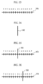
- an apparatus called a Maddox wing having a partition plate for separating a left eye field of view and a right eye field of view so that a horizontal scale 101 shown in Fig. 23 and a vertical bar 102 shown in Fig. 24 are respectively seen with the left eye and the right eye.
- the vertical bar 102 is so seen as to coincide with the reference position "0" of the horizontal scale 101, as shown in Fig. 25.
- the vertical bar 102 is seen in a position deviating from the reference position "0" of the horizontal scale 101, as shown in Fig. 26.
- the person to be inspected answers a position, where the vertical bar 102 is seen, on the horizontal scale 101, and an inspecting person judges whether or not the person to be inspected is normal on the basis of the answer. Therefore, the amount of deviation of the vertical bar 102 from the reference position of the horizontal scale 101 cannot be objectively or automatically measured. That is, the degree of strabismus cannot be objectively or automatically measured.
- An object of the present invention is to provide a binocular view function inspecting apparatus and a binocular view function inspecting method, in which the degree of strabismus can be objectively measured.
- Another object of the present invention is to provide a binocular view function inspecting apparatus and a binocular view function inspecting method, in which the degree of strabismus can be automatically measured.
- Still another object of the present invention is to provide a strabismus correcting apparatus and a strabismus correcting method, in which strabismus can be corrected.
- a binocular view function inspecting apparatus is characterized by comprising display means for displaying a reference image and an index image on a three-dimensional display (3D) device with either one of the images taken as a left eye image and the other image taken as a right eye image, first input means for causing a person to be inspected to input a movement command to move a display position of the index image in order that a predetermined reference position of the reference image and the display position of the index image coincide with each other, index image movement means for moving the display position of the index image on the basis of the movement command from the first input means, second input means for causing the person to be inspected to provide, when the person to be inspected visually recognizes that the reference position of the reference image and the display position of the index image coincide with each other, confirmation input indicating that the person to be inspected visually recognizes the coincidence, and calculation means for calculating the amount of deviation of the index image from the reference position of the reference image when the confirmation input is provided.
- 3D three-dimensional display
- the amount of deviation of the index image from the reference position of the reference image can be objectively and automatically measured.
- the reporting means include one for displaying the results of judgment on a display device for an inspecting person, and one for outputting the results of judgment by a printer.
- the amount of deviation calculated by the calculation means may be displayed on the display device for an inspecting person, and may be outputted by the printer. Further, the amount of deviation calculated by the calculation means may be stored in a storage device such as a hard disk. Consequently, the results of inspection corresponding to a plurality of persons to be inspected can be utilized as a data base.
- a binocular view function inspecting method is characterized by comprising a first step of displaying a reference image and an index image on a 3D display device with either one of the images taken as a left eye image and the other image taken as a right eye image, a second step of causing a person to be inspected to input a movement command to move a display position of the index image in order that a predetermined reference position of the reference image and the display position of the index image coincide with each other, a third step of moving the display position of the index image on the basis of the inputted movement command, a fourth step of causing the person to be inspected to provide, when the person to be inspected visually recognizes that the reference position of the reference image and the display position of the index image coincide with each other, confirmation input indicating that the person to be inspected visually recognizes the coincidence, and a fifth step of calculating the amount of deviation of the index image from the reference position of the reference image when the confirmation input is provided.
- the amount of deviation of the index image from the reference position of the reference image can be objectively and automatically measured.
- Examples of a method of reporting the results of the judgment in the sixth step to the inspecting person include a method of displaying the results of judgment on a display device for an inspecting person and a method of outputting the results of judgment by a printer.
- the amount of deviation calculated in the fifth step may be displayed on the display device for an inspecting person, and may be outputted by the printer. Further, the amount of deviation calculated in the fifth step may be stored in a storage device such as a hard disk. Consequently, the results of inspection corresponding to a plurality of persons to be inspected can be utilized as a data base.
- a computer readable recording medium on which a binocular view function inspecting program is recorded according to the present invention is characterized in that the program causes a computer to carry out the steps of displaying a reference image and an index image on a 3D display device with either one of the images taken as a left eye image and the other image taken as a right eye image, moving a display position of the index image, when a movement command to move the display position of the index image is inputted by a person to be inspected in order that a predetermined reference position of the reference image and the display position of the index image coincide with each other, on the basis of the movement command, and calculating the amount of deviation of the index image from the reference position of the reference image by the person to be inspected visually recognizing that the reference position of the reference image and the display position of the index image coincide with each other when confirmation input indicating that the person to be inspected visually recognizes the coincidence is provided by the person to be inspected.
- a strabismus correcting apparatus is characterized by comprising strabismic angle measurement means for measuring information relating to the strabismic angle of a person to be inspected, and strabismus correcting means for displaying a strabismus correcting image comprising a left eye image and a right eye image on a 3D display device on the basis of the information relating to the strabismic angle measured by the strabismic angle measurement means, the strabismus correcting means comprising means for displaying the strabismus correcting image comprising the left eye image and the right eye image which have an amount of deviation corresponding to the strabismic angle of the person to be inspected on the 3D display device, and means for gradually decreasing the amount of deviation between the left eye image and the right eye image in the strabismus correcting image displayed on the 3D display device.
- Examples of the strabismic angle measurement means include one comprising display means for displaying a reference image and an index image on the 3D display device with either one of the images taken as a left eye image and the other image taken as a right eye image, first input means for causing the person to be inspected to input a movement command to move a display position of the index image in order that a predetermined reference position of the reference image and the display position of the index image coincide with each other, index image movement means for moving the display position of the index image on the basis of the movement command from the first input means, second input means for causing the person to be inspected to provide, when the person to be inspected visually recognizes that the reference position of the reference image and the display position of the index image coincide with each other, confirmation input indicating that the person to be inspected visually recognizes the coincidence, and calculation means for calculating the amount of deviation of the index image from the reference position of the reference image when the confirmation input is provided, to obtain information relating to the strabismic angle of the person to be inspected.
- a strabismus correcting method is characterized by comprising a strabismic angle measuring step of measuring information relating to the strabismic angle of a person to be inspected, and a strabismus correcting step of displaying a strabismus correcting image comprising a left eye image and a right eye image on a 3D display device on the basis of the information relating to the strabismic angle measured by the strabismic angle measurement step, the strabismus correcting step comprising the step of displaying the strabismus correcting image comprising the left eye image and the right eye image which have an amount of deviation corresponding to the strabismic angle of the person to be inspected on the 3D display device, and the step of gradually decreasing the amount of deviation between the left eye image and the right eye image in the strabismus correcting image displayed on the 3D display device.
- Examples of the strabismic angle measuring step include one comprising a first step of displaying a reference image and an index image on the 3D display device with either one of the images taken as a left eye image and the other image taken as a right eye image, a second step of causing the person to be inspected to input a movement command to move a display position of the index image in order that a predetermined reference position of the reference image and the display position of the index image coincide with each other, a third step of moving the display position of the index image on the basis of the movement command from the first input means, a fourth step of causing the person to be inspected to provide, when the person to be inspected visually recognizes that the reference position of the reference image and the display position of the index image coincide with each other, confirmation input indicating that the person to be inspected visually recognizes the coincidence, and a fifth step of calculating the amount of deviation of the index image from the reference position of the reference image when the confirmation input is provided, to obtain information relating to the strabismic angle of the person to be
- a computer readable recording medium on which a strabismus correcting program is recorded according to the present invention is characterized in that the program causes a computer to carry out a strabismic angle measuring step of measuring information relating to the strabismic angle of a person to be inspected, and a strabismus correcting step of displaying a strabismus correcting image comprising a left eye image and a right eye image on a 3D display device on the basis of the information relating to the strabismic angle measured by the strabismic angle measuring step, the strabismus correcting step comprising the step of displaying the strabismus correcting image comprising the left eye image and the right eye image which have an amount of deviation corresponding to the strabismic angle of the person to be inspected on the 3D display device, and the step of gradually decreasing the amount of deviation between the left eye image and the right eye image in the strabismus correcting image displayed on the 3D display device.
- Examples of the strabismic angle measuring step include one comprising the steps of displaying a reference image and an index image on a 3D display device with either one of the images taken as a left eye image and the other image taken as a right eye image, moving a display position of the index image, when a movement command to move the display position of the index image is inputted by a person to be inspected in order that a predetermined reference position of the reference image and the display position of the index image coincide with each other, on the basis of the movement command, calculating the amount of deviation of the index image from the reference position of the reference image by the person to be inspected visually recognizing that the reference position of the reference image and the display position of the index image coincide with each other when confirmation input indicating that the person to be inspected visually recognizes the coincidence is provided by the person to be inspected.
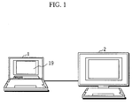
- Fig. 1 illustrates the appearance of a binocular view function inspecting apparatus.
- the binocular view function inspecting apparatus is constituted by a personal computer 1 operated by an inspecting person and a three-dimensional display device (3D display device) 2 providing an image for inspecting a binocular view function to a person to be inspected.
- a personal computer 1 operated by an inspecting person
- a three-dimensional display device (3D display device) 2 providing an image for inspecting a binocular view function to a person to be inspected.
- the personal computer 1 a so-called notebook-sized personal computer comprising a two-dimensional display (2D display) 19 is used in this example.
- An example of the 3D display device 2 is one of a parallax barrier type.
- Fig. 2 illustrates the construction of the binocular view function inspecting apparatus.
- a personal computer 1 is controlled by a CPU 11.
- a hard disk 12 storing its program and the like and a memory 13 storing necessary data.
- an input device 14 including a mouse, a speaker 20 and a printer 21 are connected to the CPU 11.
- first frame memory 15 and a second frame memory 16 are connected to the CPU 11.
- the first frame memory 15 is connected to a 2D display 19 through a D/A (digital-to-analog) converter 17.
- the second frame memory 16 is connected to a 3D display device 2 through a D/A converter 18.
- Fig. 3 illustrates the construction of a display section in the 3D display device 2.
- Image information 30 comprising a left eye reduced image 30L obtained by reducing an original left eye image to one-half in the horizontal direction and a right eye reduced image 30R obtained by reducing an original right eye image to one-half in the horizontal direction is sent to the 3D display device 2 from the personal computer 1, as shown in Fig. 4.
- the 3D display device 2 respectively decomposes the left eye reduced image and the right eye reduced image which are sent into longwise strip-shaped images, alternately arrange the left eye strip-shaped images 31L and the right eye strip-shaped images 31R in the horizontal direction and displays the images on a liquid crystal panel 41, as shown in Figs. 3 and 4.
- a back light 42 is disposed behind the liquid crystal panel 41.
- a parallax barrier 43 in which apertures 43a and barriers 43b are alternately arranged in the horizontal direction is disposed ahead of the liquid crystal panel 41.
- a person to be inspected views an image on the liquid crystal panel 41 through the parallax barrier 43, so that only the left eye strip-shaped images and only the right eye strip-shaped images are respectively seen with the left eye L and the right eye R.
- Fig. 5 shows the procedure for inspection processing of a binocular view function.
- Fig. 8 illustrates one example of an initial screen displayed on the 2D display 19 (hereinafter referred to as a screen for an inspecting person).
- a start button 51 and an end button 52 are displayed on the initial screen.
- the start button 51 When the start button 51 is pushed, the image representing the cage and the image representing the lion are read out from the hard disk 12, and are stored in the memory 13 (step 1). Their composite image is sent to the 2D display 19 through the frame memory 15 and the D/A converter 17, and is displayed on the 2D display 19 (step 2).
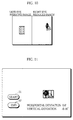
- One example of the image is illustrated in Fig. 9.
- an image representing a cage 61 and an image representing a lion 62 are displayed in addition to the start button 51 and the end button 52, and their horizontal deviation and their vertical deviation are displayed.
- the image representing the cage and the image representing the lion which are stored in the memory 13 are taken as a left eye image and a right eye image and are reduced to one-half in the horizontal direction, respectively, to produce an image corresponding to one frame.
- One example of a left eye reduced image and a right eye reduced image respectively corresponding to the images representing the cage and the lion which are displayed on the screen for an inspecting person shown in Fig. 9 is illustrated in Fig. 10.
- the produced image corresponding to one frame is sent to the 3D display device 2 through the frame memory 16 and the D/A converter 18.
- the 3D display device 2 respectively decomposes the left eye reduced image and the right eye reduced image which are sent into longwise strip-shaped images, alternately arranges the left eye strip-shaped images and the right eye strip-shaped images in the horizontal direction and displays the images on the liquid crystal panel 41 (hereinafter referred to as a screen for a person to be inspected) (step 3). Consequently, the same images as the images displayed on the screen for an inspecting person, that is, the image representing the cage and the image representing the lion are displayed on the screen for a person to be inspected. Only the image representing the cage and only the image representing the lion are respectively seen with the left eye and the right eye of a person to be inspected.
- the initial position of the mouse is stored in the memory 13 (step 4). Thereafter, a voice message "Cage a lion" is outputted from the speaker 20 (step 5).
- An operator so operates the mouse (included in the input device 14) that the lion is caged, and clicks the mouse when the lion has been caged.
- the current position of the mouse is stored in the memory 13 (step 6).
- the image representing the lion is moved on the screen for an inspecting person and the screen for a person to be inspected on the basis of the direction in which the mouse is moved and the amount of movement thereof (step 7).
- a new image displayed on the screen for an inspecting person and a new image sent to the 3D display device 2 are produced on the basis of the image representing the cage and the image representing the lion which are stored in the memory 13.
- the amount of deviation (the amount of deviation in the horizontal direction and the amount of deviation in the vertical direction) between the image representing the cage and the image representing the lion is calculated on the basis of the direction in which the mouse is moved and the amount of movement thereof, and the calculated amount of deviation is displayed on the screen for an inspecting person (step 8).
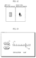
- Fig. 11 One example of the screen for an inspecting person in a case where the mouse is clicked is shown in Fig. 11. Further, a left eye reduced image and a right eye reduced image respectively corresponding to the images representing the cage and the lion which are displayed on the screen for an inspecting person shown in Fig. 11 are illustrated in Fig. 12.
- step 10 "normal” is displayed if the amount of deviation between the image representing the cage and the image representing the lion is within an allowable range, while “reinspection” is displayed on the screen for an inspecting person if it is outside the allowable range. Further, the amount of deviation corresponding to the person to be inspected is stored in the hard disk 12 (step 11), and the results of the inspection is outputted by the printer 21 (step 12).
- the image representing the cage 61 which is a reference image may be replaced with an image representing a horizontal scale 71
- the image representing the lion 62 which is an index image may be replaced with an image representing a vertical bar 72.
- Fig. 13 illustrates a screen for an inspecting person in a case where the image representing the horizontal scale 71 and the image representing the vertical bar 72 are used.
- Fig. 14 illustrates a left eye reduced image corresponding to the image representing the horizontal scale 71 and a right eye reduced image corresponding to the image representing the vertical bar 72 which are displayed on the screen for an inspecting person shown in Fig. 13. In this case, the amount of deviation of the image representing the vertical bar 72 from the reference position "0" of the image representing the horizontal scale 71 is displayed on the screen for an inspecting person.
- the image representing the cage 61 which is a reference image may be replaced with an image representing a vertical image 81
- the image representing the lion 62 which is an index image may be replaced with an image representing a horizontal bar 82.
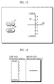
- Fig. 15 illustrates a screen for an inspecting person in a case where the image representing the vertical scale 81 and the image representing the horizontal bar 82 are used.
- Fig. 16 illustrates a left eye reduced image corresponding to the image representing the vertical scale 81 and a right eye reduced image corresponding to the image representing the horizontal bar 82 which are displayed on the screen for an inspecting person shown in Fig. 15. In this case, the amount of deviation of the image representing the horizontal bar 82 from the reference position "0" of the image representing the vertical scale 81 is displayed on the screen for an inspecting person.
- the amount of deviation may be calculated by using a strip-shaped image 91 as a reference image and using a strip-shaped image 92 as an index image moved upon being operated by a person to be inspected, setting a plurality of display positions of the reference image within one screen, and moving the index image for each set display position.
- Fig. 17 illustrates a screen for an inspecting person, which shows that the reference image 91 and the index image 92 which are hatched have been already inspected, and the reference image 91 and the index image 92 which are solid are being currently inspected.
- a left eye reduced image corresponding to the reference image 91 which is currently inspected and a right eye reduced image corresponding the index image 92 which is currently inspected are illustrated in Fig. 18.
- the display device of a parallax barrier type is used as a 3D display device
- a 3D display device using no glasses such as a 3D display device of a lenticular type may be used.
- a 3D display device using both polarizing glasses and liquid crystal shutter glasses may be used.
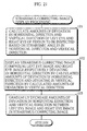
- Fig. 19 shows the procedure for strabismus correction processing.
- Strabismic angle measurement processing is first performed (step 101). It is judged whether or not a person to be inspected has a squint on the basis of information relating to a strabismic angle measured by the strabismic angle measurement processing (step 102). When it is judged that the person to be inspected does not have a squint, that is, it is judged that the person to be inspected is normal, no correction is required, whereby the current processing is terminated. When it is judged that the person to be inspected has a squint, that is, it is judged that the person to be inspected is not normal, strabismus correcting image display processing is performed (step 103).
- Fig. 20 shows the detailed procedure for the strabismic angle measurement processing in the step 101 shown in Fig. 19.
- FIG. 8 illustrates one example of an initial screen displayed on a 2D display 19 (hereinafter referred to as a screen for an inspecting person).
- a start button 51 and an end button 52 are displayed on the initial screen.
- the start button 51 When the start button 51 is pushed, the image representing the cage and the image representing the lion are read out from the hard disk 12, and are stored in a memory 13 (step 111). Their composite image is sent to the 2D display 19 through a frame memory 15 and a D/A converter 17, and is displayed on the 2D display 19 (step 112).
- a frame memory 15 and a D/A converter 17 One example of the image is illustrated in Fig. 9.
- an image representing a cage 61 and an image representing a lion 62 are displayed in addition to the start button 51 and the end button 52, and their horizontal deviation and their vertical deviation are displayed.
- the image representing the cage and the image representing the lion which are stored in the memory 13 are taken as a left eye image and a right eye image and are reduced to one-half in the horizontal direction, respectively, to produce an image corresponding to one frame.
- One example of a left eye reduced image and a right eye reduced image respectively corresponding to the images representing the cage and the lion which are displayed on the screen for an inspecting person shown in Fig. 9 is illustrated in Fig. 10.
- the produced image corresponding to one frame is sent to a 3D display device 2 through a frame memory 16 and a D/A converter 18.
- the 3D display device 2 respectively decomposes the left eye reduced image and the right eye reduced image which are sent into longwise strip-shaped images, alternately arranges the left eye strip-shaped images and the right eye strip-shaped images in the horizontal direction and displays the images on a liquid crystal panel 41 (hereinafter referred to as a screen for a person to be inspected) (step 113). Consequently, the same images as the images displayed on the screen for an inspecting person, that is, the image representing the cage and the image representing the lion are displayed on the screen for a person to be inspected. Only the image representing the cage and only the image representing the lion are respectively seen with the left eye and the right eye of a person to be inspected.
- a voice message "Cage a lion" is outputted from a speaker 20 (step 115).
- An operator so operates the mouse (included in an input device 14) that the lion is caged, and clicks the mouse when the lion has been caged.
- the current position of the mouse is stored in the memory 13 (step 116).
- the image representing the lion is moved on the screen for an inspecting person and the screen for a person to be inspected on the basis of the direction in which the mouse is moved and the amount of movement thereof (step 117).
- a new image displayed on the screen for an inspecting person and a new image sent to the 3D display device 2 are produced on the basis of the image representing the cage and the image representing the lion which are stored in the memory 13.
- Strabismic angles in the horizontal direction and the vertical direction between the image representing the cage and the image representing the lion are calculated on the basis of the direction in which the mouse is moved and the amount of movement thereof, and the calculated strabismic angles are displayed on the screen for an inspecting person (step 118).
- the program is returned to the step 102 shown in Fig. 9.
- the processing in the steps 116 to 118 is repeatedly performed.
- the answer is in the affirmative in the step 119, after which the program proceeds to the step 120.
- the strabismic angles in the horizontal direction and the vertical direction which are finally calculated are stored in the hard disk 12.
- Fig. 11 One example of the screen for an inspecting person in a case where the mouse is clicked is shown in Fig. 11. Further, a left eye reduced image and a right eye reduced image respectively corresponding to the images representing the cage and the lion which are displayed on the screen for an inspecting person shown in Fig. 11 are illustrated in Fig. 12.
- step 102 shown in Fig. 19 it is judged whether or not the strabismic angles measured in the strabismic angle measurement processing in the step 101 are within an allowable angle. If the strabismic angles are within the allowable range, no strabismus correction is required, whereby the current processing is terminated. If the strabismic angles are outside the allowable range, the program proceeds to strabismus correcting image display processing in the step 103.
- Fig. 21 shows the detailed procedure for the strabismus correcting image display processing in the step 103 shown in Fig. 19.
- the amounts of deviation in the horizontal direction of the left eye and the right eye of the person to be inspected are calculated on the basis of the strabismic angle in the horizontal direction, and the amounts of deviation in the vertical direction of the left eye and the right eye of the person to be inspected are calculated on the basis of the strabismic angle in the vertical direction (step 121).
- a strabismus correcting image comprising a left eye image and a right eye image which respectively deviate in the horizontal direction by the calculated amounts of deviation in the horizontal direction and respectively deviate in the vertical direction by the calculated amounts of deviation in the vertical direction is displayed on the 3D display device 2 (step 122).
- the strabismus correcting image is first read out from the hard disk 12, and is stored in the memory 13.
- a left eye image and a right eye image which respectively deviate in the horizontal direction by the amounts of deviation in the horizontal direction calculated in the step 122 and respectively deviate in the vertical direction by the amounts of deviation in the vertical direction calculated in the step 122 are produced from the strabismus correcting image stored in the memory 13, and are respectively reduced to one-half in the horizontal direction, to produce an image corresponding to one frame.
- the produced image corresponding to one frame is sent to the 3D display device 2 through the frame memory 16 and the D/A converter 18.
- the 3D display device 2 respectively decomposes the left eye reduced image and the right eye reduced image which are sent into longwise strip-shaped images, alternately arranges the left eye strip-shaped images and the right eye strip-shaped images in the horizontal direction and displays the images on the liquid crystal panel 41 (hereinafter referred to as a screen for a person to be inspected).
- Fig. 22a illustrates the left eye image L and the right eye image R in this case and the strabismus correcting image displayed on the 3D display device 2.
- the person to be inspected views an index SL included in the left eye strabismus correcting image displayed on the 3D display device 2 with the left eye, and views an index SR included in the right eye strabismus correcting image with the right eye.
- the amounts of deviation in the horizontal direction and the vertical direction between the left eye image and the right eye image in the strabismus correcting image displayed on the 3D display device 2 are gradually decreased (step 123). Specifically, the left eye image and the right eye image are so produced that the amounts of deviation in the horizontal direction and the vertical direction are gradually decreased, and are displayed on the 3D display device 2. Consequently, the left eye image and the right eye image in a case where the amounts of deviation in the horizontal direction and the vertical direction therebetween are zero are finally produced, and are displayed on the 3D display device 2.
- Fig. 22b illustrates a left eye image L and a right eye image R in a case where the amounts of deviation therebetween are decreased and a strabismus correcting image displayed on the 3D display device 2.
- Fig. 22c illustrates a left eye image L and a right eye image R in a case where the amounts of deviation therebetween are zero and a strabismus correcting image displayed on the 3D display device 2.
- the person to be inspected first views the left eye image and the right eye image which have an amount of deviation corresponding to his or her own strabismic angle, whereby an image caught by the left eye and an image caught by the right eye are so seen that they coincide with each other.
- the amount of deviation between the left eye image and the right eye image is so gradually decreased as to be close to zero which is a normal value, whereby the person to be inspected attempts to so unconsciously catch the left eye image and the right eye image that they coincide with each other.
- the strabismus is corrected by such an unconscious function.
- strabismus correcting image a moving image is used in order that the person to be inspected can continue to view the image with interest.
Landscapes
- Health & Medical Sciences (AREA)
- Life Sciences & Earth Sciences (AREA)
- Physics & Mathematics (AREA)
- Engineering & Computer Science (AREA)
- Surgery (AREA)
- Animal Behavior & Ethology (AREA)
- Biomedical Technology (AREA)
- Heart & Thoracic Surgery (AREA)
- Medical Informatics (AREA)
- Molecular Biology (AREA)
- Biophysics (AREA)
- Ophthalmology & Optometry (AREA)
- General Health & Medical Sciences (AREA)
- Public Health (AREA)
- Veterinary Medicine (AREA)
- Multimedia (AREA)
- Signal Processing (AREA)
- General Physics & Mathematics (AREA)
- Optics & Photonics (AREA)
- Eye Examination Apparatus (AREA)
Abstract
Description
Claims (17)
- A binocular view function inspecting apparatus comprising:display means for displaying a reference image and an index image on a three-dimensional display device with either one of the images taken as a left eye image and the other image taken as a right eye image;first input means for causing a person to be inspected to input a movement command to move a display position of the index image in order that a predetermined reference position of the reference image and the display position of the index image coincide with each other;index image movement means for moving the display position of the index image on the basis of the movement command from the first input means;second input means for causing the person to be inspected to provide, when the person to be inspected visually recognizes that the reference position of the reference image and the display position of the index image coincide with each other, confirmation input indicating that the person to be inspected visually recognizes the coincidence; andcalculation means for calculating the amount of deviation of the index image from the reference position of the reference image when the confirmation input is provided.
- The binocular view function inspecting apparatus according to claim 1, further comprisingjudgment means for judging whether or not the person to be inspected is normal on the basis of the amount of deviation calculated by the calculation means, andreporting means for reporting the results of the judgment by the judgment means to an inspecting person.
- A binocular view function inspecting method comprising:a first step of displaying a reference image and an index image on a three-dimensional display device with either one of the images taken as a left eye image and the other image taken as a right eye image;a second step of causing a person to be inspected to input a movement command to move a display position of the index image in order that a predetermined reference position of the reference image and the display position of the index image coincide with each other;a third step of moving the display position of the index image on the basis of the inputted movement command;a fourth step of causing the person to be inspected to provide, when the person to be inspected visually recognizes that the reference position of the reference image and the display position of the index image coincide with each other, confirmation input indicating that the person to be inspected visually recognizes the coincidence; anda fifth step of calculating the amount of deviation of the index image from the reference position of the reference image when the confirmation input is provided.
- The binocular view function inspecting method according to claim 3, further comprisinga sixth step of judging whether or not the person to be inspected is normal on the basis of the amount of deviation calculated in the fifth step, anda seventh step of reporting the results of the judgment in the sixth step to an inspecting person.
- A computer readable recording medium on which a binocular view function inspecting program is recorded, said program causing a computer to carry out the following steps:displaying a reference image and an index image on a three-dimensional display device with either one of the images taken as a left eye image and the other image taken as a right eye image;moving a display position of the index image, when a movement command to move the display position of the index image is inputted by a person to be inspected in order that a predetermined reference position of the reference image and the display position of the index image coincide with each other, on the basis of the movement command; andcalculating the amount of deviation of the index image from the reference position of the reference image by the person to be inspected visually recognizing that the reference position of the reference image and the display position of the index image coincide with each other when confirmation input indicating that the person to be inspected visually recognizes the coincidence is provided by the person to be inspected.
- A strabismus correcting apparatus comprising a strabismic angle measurement means for measuring information relating to the strabismic angle of a person to be inspected, and strabismus correcting means for displaying a strabismus correcting image comprising a left eye image and a right eye image on a three-dimensional display device on the basis of the information relating to the strabismic angle measured by the strabismic angle measurement means,the strabismus correcting means comprising means for displaying the strabismus correcting image comprising the left eye image and the right eye image which have an amount of deviation corresponding to the strabismic angle of the person to be inspected on the three-dimensional display device, and means for gradually decreasing the amount of deviation between the left eye image and the right eye image in the strabismus correcting image displayed on the three-dimensional display device.
- The strabismus correcting apparatus according to claim 6, whereinthe strabismic angle measurement means comprisesdisplay means for displaying a reference image and an index image on the three-dimensional display device with either one of the images taken as a left eye image and the other image taken as a right eye image,first input means for causing the person to be inspected to input a movement command to move a display position of the index image in order that a predetermined reference position of the reference image and the display position of the index image coincide with each other,index image movement means for moving the display position of the index image on the basis of the movement command from the first input means,second input means for causing the person to be inspected to provide, when the person to be inspected visually recognizes that the reference position of the reference image and the display position of the index image coincide with each other, confirmation input indicating that the person to be inspected visually recognizes the coincidence, andcalculation means for calculating the amount of deviation of the index image from the reference position of the reference image when the confirmation input is provided, to obtain information relating to the strabismic angle of the person to be inspected.
- The strabismus correcting apparatus according to claim 6, whereinthe strabismus correcting image is a moving image.
- The strabismus correcting apparatus according to claim 7, whereinthe strabismus correcting image is a moving image.
- A strabismus correcting method comprising a strabismic angle measuring step of measuring information relating to the strabismic angle of a person to be inspected, and a strabismus correcting step of displaying a strabismus correcting image comprising a left eye image and a right eye image on a three-dimensional display device on the basis of the information relating to the strabismic angle measured by the strabismic angle measuring step,the strabismus correcting step comprising the step of displaying the strabismus correcting image comprising the left eye image and the right eye image which have an amount of deviation corresponding to the strabismic angle of the person to be inspected on the three-dimensional display device, and the step of gradually decreasing the amount of deviation between the left eye image and the right eye image in the strabismus correcting image displayed on the three-dimensional display device.
- The strabismus correcting method according to claim 10, whereinthe strabismic angle measuring step comprisesa first step of displaying a reference image and an index image on the three-dimensional display device with either one of the images taken as a left eye image and the other image taken as a right eye image,a second step of causing the person to be inspected to input a movement command to move a display position of the index image in order that a predetermined reference position of the reference image and the display position of the index image coincide with each other,a third step of moving the display position of the index image on the basis of the movement command from the first input means,a fourth step of causing the person to be inspected to provide, when the person to be inspected visually recognizes that the reference position of the reference image and the display position of the index image coincide with each other, confirmation input indicating that the person to be inspected visually recognizes the coincidence, anda fifth step of calculating the amount of deviation of the index image from the reference position of the reference image when the confirmation input is provided, to obtain information relating to the strabismic angle of the person to be inspected.
- The strabismus correcting method according to claim 10, whereinthe strabismus correcting image is a moving image.
- The strabismus correcting method according to claim 11, whereinthe strabismus correcting image is a moving image.
- A computer readable recording medium on which a strabismus correcting program is recorded, said program causing a computer to carry out a strabismic angle measuring step of measuring information relating to the strabismic angle of a person to be inspected, and a strabismus correcting step of displaying a strabismus correcting image comprising a left eye image and a right eye image on a three-dimensional display device on the basis of the information relating to the strabismic angle measured by the strabismic angle measuring step,the strabismus correcting step comprising the step of displaying the strabismus correcting image comprising the left eye image and the right eye image which have an amount of deviation corresponding to the strabismic angle of the person to be inspected on the three-dimensional display device, and the step of gradually decreasing the amount of deviation between the left eye image and the right eye image in the strabismus correcting image displayed on the three-dimensional display device.
- A computer readable recording medium on which the strabismus correcting program as set forth in the claim 14 is recorded, whereinthe strabismic angle measuring step comprises the steps ofdisplaying a reference image and an index image on the three-dimensional display device with either one of the images taken as a left eye image and the other image taken as a right eye image,moving a display position of the index image, when a movement command to move the display position of the index image is inputted by a person to be inspected in order that a predetermined reference position of the reference image and the display position of the index image coincide with each other, on the basis of the movement command,calculating the amount of deviation of the index image from the reference position of the reference image by the person to be inspected visually recognizing that the reference position of the reference image and the display position of the index image coincide with each other when confirmation input indicating that the person to be inspected visually recognizes the coincidence is provided by the person to be inspected.
- A computer readable recording medium on which the strabismus correcting program as set forth in the claim 14 is recorded, whereinthe strabismus correcting image is a moving image.
- A computer readable recording medium on which the strabismus correcting program as set forth in the claim 15 is recorded, whereinthe strabismus correcting image is a moving image.
Applications Claiming Priority (4)
| Application Number | Priority Date | Filing Date | Title |
|---|---|---|---|
| JP250449/96 | 1996-09-20 | ||
| JP8250449A JP2999963B2 (en) | 1996-09-20 | 1996-09-20 | Binocular function test apparatus and test method |
| JP125431/97 | 1997-05-15 | ||
| JP9125431A JPH10314211A (en) | 1997-05-15 | 1997-05-15 | Squint correcting device and computer readable recording medium recording squint correcting program |
Publications (3)
| Publication Number | Publication Date |
|---|---|
| EP0830839A2 true EP0830839A2 (en) | 1998-03-25 |
| EP0830839A3 EP0830839A3 (en) | 1999-04-28 |
| EP0830839B1 EP0830839B1 (en) | 2011-07-20 |
Family
ID=26461874
Family Applications (1)
| Application Number | Title | Priority Date | Filing Date |
|---|---|---|---|
| EP97116287A Expired - Lifetime EP0830839B1 (en) | 1996-09-20 | 1997-09-18 | Binocular view function inspecting apparatus and inspecting method |
Country Status (2)
| Country | Link |
|---|---|
| US (1) | US5877840A (en) |
| EP (1) | EP0830839B1 (en) |
Cited By (13)
| Publication number | Priority date | Publication date | Assignee | Title |
|---|---|---|---|---|
| DE19809591A1 (en) * | 1998-03-06 | 1999-09-09 | Neuhof | Apparatus and method for presenting moving or still visual impressions for automatically and comprehensively acquiring many parameters of the viewer |
| DE19816486A1 (en) * | 1998-04-14 | 1999-11-04 | Bernd Woop | Universal modular eye testing system |
| WO1999066829A1 (en) * | 1998-06-23 | 1999-12-29 | Plusvision, Inc. | Device for examining ocular motility |
| GB2353869A (en) * | 1999-09-01 | 2001-03-07 | Assaf Ahmed Abdel Rahman | Synoptophore using computer display to measure squint |
| WO2003092482A1 (en) * | 2002-05-04 | 2003-11-13 | The University Of Nottingham | Ocular display apparatus for assessment and measurement of and for treatment of ocular disorders, and methods therefor |
| US7367671B2 (en) | 2002-02-08 | 2008-05-06 | Novavision, Inc. | Process and device for the training of human vision |
| US7594728B2 (en) | 2005-12-16 | 2009-09-29 | Novavision, Inc. | Adjustable device for vision testing and therapy |
| US7642990B2 (en) | 2004-06-15 | 2010-01-05 | Novavision, Inc. | Method and device for guiding a user's head during vision training |
| WO2010108495A1 (en) * | 2009-03-26 | 2010-09-30 | Bruun-Jensen Joergen | A system for clinical examination of some visual functions using lenticular optics |
| EP2381294A3 (en) * | 2010-04-21 | 2011-12-14 | Samsung Electronics Co., Ltd. | Stereoscopic glasses with a prism and display system including the glasses |
| EP2398245A3 (en) * | 2010-06-17 | 2014-04-23 | Samsung Electronics Co., Ltd. | Display apparatus and 3d image acquisition-examination method thereof |
| EP2826413A1 (en) | 2007-10-23 | 2015-01-21 | McGill University | Binocular vision assessment and/or therapy |
| WO2015078720A1 (en) * | 2013-11-28 | 2015-06-04 | Ipro Gmbh | Method for representing optotypes, optotype representation, associated use and image output device |
Families Citing this family (11)
| Publication number | Priority date | Publication date | Assignee | Title |
|---|---|---|---|---|
| KR100612586B1 (en) * | 1998-07-21 | 2007-12-04 | 엘지전자 주식회사 | Apparatus For Testing Squint in Head Mounted Display |
| US6139152A (en) | 2000-02-28 | 2000-10-31 | Ghahramani; Bahador | Electronic depth perception testing system and apparatus for conducting depth perception tests |
| DE10207839B4 (en) * | 2001-02-27 | 2010-07-15 | Constanze Schmidt | Method and apparatus for programmable biofeedback snare therapy |
| US6644811B2 (en) | 2001-04-11 | 2003-11-11 | Ferris State University | Oculomotor balance tester |
| BR0318661A (en) * | 2003-12-19 | 2006-11-28 | Tdvision Corp S A De C V | 3d video game system |
| US7482888B1 (en) * | 2007-07-12 | 2009-01-27 | Zerog Wireless, Inc. | Fast startup resonant element oscillator |
| US8266168B2 (en) * | 2008-04-24 | 2012-09-11 | Lexisnexis Risk & Information Analytics Group Inc. | Database systems and methods for linking records and entity representations with sufficiently high confidence |
| US8002408B2 (en) * | 2009-08-03 | 2011-08-23 | Nike, Inc. | Anaglyphic depth perception training or testing |
| JP2012085252A (en) * | 2010-09-17 | 2012-04-26 | Panasonic Corp | Image generation device, image generation method, program, and recording medium with program recorded thereon |
| DE102011089705A1 (en) | 2011-12-22 | 2013-06-27 | Carl Zeiss Vision International Gmbh | vision testing |
| CN106821696B (en) * | 2017-02-08 | 2021-07-27 | 王三铭 | Far-distance reading and writing device for preventing and treating myopia of students and using method |
Family Cites Families (8)
| Publication number | Priority date | Publication date | Assignee | Title |
|---|---|---|---|---|
| US3025754A (en) * | 1957-05-08 | 1962-03-20 | Mirsky David | Strabismic fusion measure and training apparatus |
| US4057054A (en) * | 1976-05-20 | 1977-11-08 | Giannone Frank C | Eye treatment apparatus |
| FR2463606B1 (en) * | 1979-08-22 | 1986-04-11 | Essilor Int | DEVICE FOR CONTROLLING THE PHORIA OF AN INDIVIDUAL IN CLOSE VIEW |
| US4961640A (en) * | 1982-08-20 | 1990-10-09 | Irlen Helen L | Method and apparatus of treatment of symptoms of the Irlen syndrom |
| US4869589A (en) * | 1987-11-30 | 1989-09-26 | United Technologies Corporation | Automated visual screening system |
| US5235361A (en) * | 1990-12-12 | 1993-08-10 | Selwyn Super | Stereoscopic vision testing apparatus |
| GB9208679D0 (en) * | 1992-04-22 | 1992-06-10 | Murray Ian J | Visual display unit visibility test |
| US5309185A (en) * | 1992-06-08 | 1994-05-03 | Harper Gilberto B | Apparatus and method for objective quantitative assessment of human ocular coordination |
-
1997
- 1997-09-16 US US08/919,765 patent/US5877840A/en not_active Expired - Lifetime
- 1997-09-18 EP EP97116287A patent/EP0830839B1/en not_active Expired - Lifetime
Non-Patent Citations (1)
| Title |
|---|
| None |
Cited By (17)
| Publication number | Priority date | Publication date | Assignee | Title |
|---|---|---|---|---|
| DE19809591A1 (en) * | 1998-03-06 | 1999-09-09 | Neuhof | Apparatus and method for presenting moving or still visual impressions for automatically and comprehensively acquiring many parameters of the viewer |
| DE19816486A1 (en) * | 1998-04-14 | 1999-11-04 | Bernd Woop | Universal modular eye testing system |
| WO1999066829A1 (en) * | 1998-06-23 | 1999-12-29 | Plusvision, Inc. | Device for examining ocular motility |
| US6595641B1 (en) | 1998-06-23 | 2003-07-22 | Plusoptix Ag | Device for examining ocular motility |
| GB2353869A (en) * | 1999-09-01 | 2001-03-07 | Assaf Ahmed Abdel Rahman | Synoptophore using computer display to measure squint |
| US7367671B2 (en) | 2002-02-08 | 2008-05-06 | Novavision, Inc. | Process and device for the training of human vision |
| WO2003092482A1 (en) * | 2002-05-04 | 2003-11-13 | The University Of Nottingham | Ocular display apparatus for assessment and measurement of and for treatment of ocular disorders, and methods therefor |
| US7642990B2 (en) | 2004-06-15 | 2010-01-05 | Novavision, Inc. | Method and device for guiding a user's head during vision training |
| US7594728B2 (en) | 2005-12-16 | 2009-09-29 | Novavision, Inc. | Adjustable device for vision testing and therapy |
| EP2826413A1 (en) | 2007-10-23 | 2015-01-21 | McGill University | Binocular vision assessment and/or therapy |
| EP3329838A1 (en) | 2007-10-23 | 2018-06-06 | McGill University | Binocular vision assessment and/or therapy |
| WO2010108495A1 (en) * | 2009-03-26 | 2010-09-30 | Bruun-Jensen Joergen | A system for clinical examination of some visual functions using lenticular optics |
| EP2381294A3 (en) * | 2010-04-21 | 2011-12-14 | Samsung Electronics Co., Ltd. | Stereoscopic glasses with a prism and display system including the glasses |
| EP2398245A3 (en) * | 2010-06-17 | 2014-04-23 | Samsung Electronics Co., Ltd. | Display apparatus and 3d image acquisition-examination method thereof |
| WO2015078720A1 (en) * | 2013-11-28 | 2015-06-04 | Ipro Gmbh | Method for representing optotypes, optotype representation, associated use and image output device |
| CN105916432A (en) * | 2013-11-28 | 2016-08-31 | Ipro有限责任公司 | Method for displaying optometry font, display of optometry font, related application and image output device |
| US10143369B2 (en) | 2013-11-28 | 2018-12-04 | Ipro Gmbh | Method for representing optotypes, optotype representation, associated use and image output device |
Also Published As
| Publication number | Publication date |
|---|---|
| EP0830839A3 (en) | 1999-04-28 |
| US5877840A (en) | 1999-03-02 |
| EP0830839B1 (en) | 2011-07-20 |
Similar Documents
| Publication | Publication Date | Title |
|---|---|---|
| US5877840A (en) | Binocular view function inspecting apparatus and inspecting method | |
| US6104828A (en) | Ophthalmologic image processor | |
| TWI754375B (en) | Image processing method, electronic device and computer-readable storage medium | |
| US7616885B2 (en) | Single lens auto focus system for stereo image generation and method thereof | |
| US6198484B1 (en) | Stereoscopic display system | |
| US8085293B2 (en) | Self adjusting stereo camera system | |
| US6611283B1 (en) | Method and apparatus for inputting three-dimensional shape information | |
| US20070165129A1 (en) | Method of and apparatus for selecting a stereoscopic pair of images | |
| US5764236A (en) | Image data processing apparatus and image reproduction apparatus | |
| US20120038631A1 (en) | System and method for three-dimensional visualization of geographical data | |
| AU2003233160A1 (en) | Method for producing stereoscopic images from monoscopic images | |
| JP3157483B2 (en) | Stereoscopic inspection apparatus and computer-readable recording medium storing stereoscopic inspection program | |
| JP2999963B2 (en) | Binocular function test apparatus and test method | |
| US20210348920A1 (en) | Object Position Estimation Device and Method Therefor | |
| US20180045934A1 (en) | Medical observation device, lens driving control device, lens driving control method, program, and video microscope device | |
| CN117193530B (en) | Intelligent cabin immersive user experience method and system based on virtual reality technology | |
| Voinov et al. | Collective benefit in joint perceptual judgments: Partial roles of shared environments, meta-cognition, and feedback | |
| CN114390267B (en) | Stereoscopic image data synthesis method, device, electronic device and storage medium | |
| Yamanoue et al. | Tolerance for geometrical distortions between L/R images in 3D‐HDTV | |
| JP3462689B2 (en) | Stereoscopic function inspection device | |
| JP2000182058A (en) | Three-dimensional motion input method and three-dimensional motion input system | |
| CN116958225B (en) | A depth sensing detection method and system based on the combination of virtual and real one-way glass | |
| CN107147898B (en) | A kind of 3D display screen alignment system and method | |
| DE102020126407A1 (en) | imaging device | |
| US20120007855A1 (en) | Converting method, device and system for 3d stereoscopic cartoon, and recording medium for the same |
Legal Events
| Date | Code | Title | Description |
|---|---|---|---|
| PUAI | Public reference made under article 153(3) epc to a published international application that has entered the european phase |
Free format text: ORIGINAL CODE: 0009012 |
|
| AK | Designated contracting states |
Kind code of ref document: A2 Designated state(s): DE FR GB |
|
| PUAL | Search report despatched |
Free format text: ORIGINAL CODE: 0009013 |
|
| AK | Designated contracting states |
Kind code of ref document: A3 Designated state(s): AT BE CH DE DK ES FI FR GB GR IE IT LI LU MC NL PT SE |
|
| 17P | Request for examination filed |
Effective date: 19990819 |
|
| AKX | Designation fees paid |
Free format text: DE FR GB |
|
| 17Q | First examination report despatched |
Effective date: 20060216 |
|
| 17Q | First examination report despatched |
Effective date: 20060216 |
|
| 17Q | First examination report despatched |
Effective date: 20060216 |
|
| APBN | Date of receipt of notice of appeal recorded |
Free format text: ORIGINAL CODE: EPIDOSNNOA2E |
|
| APBR | Date of receipt of statement of grounds of appeal recorded |
Free format text: ORIGINAL CODE: EPIDOSNNOA3E |
|
| RAP1 | Party data changed (applicant data changed or rights of an application transferred) |
Owner name: NIDEK CO., LTD. |
|
| APAF | Appeal reference modified |
Free format text: ORIGINAL CODE: EPIDOSCREFNE |
|
| APBT | Appeal procedure closed |
Free format text: ORIGINAL CODE: EPIDOSNNOA9E |
|
| GRAP | Despatch of communication of intention to grant a patent |
Free format text: ORIGINAL CODE: EPIDOSNIGR1 |
|
| GRAS | Grant fee paid |
Free format text: ORIGINAL CODE: EPIDOSNIGR3 |
|
| GRAA | (expected) grant |
Free format text: ORIGINAL CODE: 0009210 |
|
| AK | Designated contracting states |
Kind code of ref document: B1 Designated state(s): DE FR GB |
|
| REG | Reference to a national code |
Ref country code: GB Ref legal event code: FG4D |
|
| REG | Reference to a national code |
Ref country code: DE Ref legal event code: R096 Ref document number: 69740252 Country of ref document: DE Effective date: 20110915 |
|
| PLBE | No opposition filed within time limit |
Free format text: ORIGINAL CODE: 0009261 |
|
| STAA | Information on the status of an ep patent application or granted ep patent |
Free format text: STATUS: NO OPPOSITION FILED WITHIN TIME LIMIT |
|
| 26N | No opposition filed |
Effective date: 20120423 |
|
| REG | Reference to a national code |
Ref country code: DE Ref legal event code: R097 Ref document number: 69740252 Country of ref document: DE Effective date: 20120423 |
|
| PGFP | Annual fee paid to national office [announced via postgrant information from national office to epo] |
Ref country code: GB Payment date: 20120912 Year of fee payment: 16 |
|
| PGFP | Annual fee paid to national office [announced via postgrant information from national office to epo] |
Ref country code: FR Payment date: 20120926 Year of fee payment: 16 Ref country code: DE Payment date: 20120912 Year of fee payment: 16 |
|
| GBPC | Gb: european patent ceased through non-payment of renewal fee |
Effective date: 20130918 |
|
| REG | Reference to a national code |
Ref country code: DE Ref legal event code: R119 Ref document number: 69740252 Country of ref document: DE Effective date: 20140401 |
|
| REG | Reference to a national code |
Ref country code: FR Ref legal event code: ST Effective date: 20140530 |
|
| PG25 | Lapsed in a contracting state [announced via postgrant information from national office to epo] |
Ref country code: GB Free format text: LAPSE BECAUSE OF NON-PAYMENT OF DUE FEES Effective date: 20130918 |
|
| PG25 | Lapsed in a contracting state [announced via postgrant information from national office to epo] |
Ref country code: DE Free format text: LAPSE BECAUSE OF NON-PAYMENT OF DUE FEES Effective date: 20140401 Ref country code: FR Free format text: LAPSE BECAUSE OF NON-PAYMENT OF DUE FEES Effective date: 20130930 |