EP0830662B1 - Engine operation detection - Google Patents
Engine operation detection Download PDFInfo
- Publication number
- EP0830662B1 EP0830662B1 EP96916709A EP96916709A EP0830662B1 EP 0830662 B1 EP0830662 B1 EP 0830662B1 EP 96916709 A EP96916709 A EP 96916709A EP 96916709 A EP96916709 A EP 96916709A EP 0830662 B1 EP0830662 B1 EP 0830662B1
- Authority
- EP
- European Patent Office
- Prior art keywords
- antenna
- vehicle
- signal
- operating
- vicinity
- Prior art date
- Legal status (The legal status is an assumption and is not a legal conclusion. Google has not performed a legal analysis and makes no representation as to the accuracy of the status listed.)
- Expired - Lifetime
Links
- 238000001514 detection method Methods 0.000 title 1
- 230000005672 electromagnetic field Effects 0.000 claims abstract description 18
- 238000000034 method Methods 0.000 claims abstract description 15
- 239000000446 fuel Substances 0.000 claims abstract description 10
- 239000003990 capacitor Substances 0.000 description 13
- 230000006698 induction Effects 0.000 description 6
- 230000000737 periodic effect Effects 0.000 description 3
- 238000001914 filtration Methods 0.000 description 2
- 230000001939 inductive effect Effects 0.000 description 2
- 238000005259 measurement Methods 0.000 description 2
- 230000000007 visual effect Effects 0.000 description 2
- 241000233805 Phoenix Species 0.000 description 1
- 238000013459 approach Methods 0.000 description 1
- 230000005540 biological transmission Effects 0.000 description 1
- 238000012512 characterization method Methods 0.000 description 1
- 238000004891 communication Methods 0.000 description 1
- 125000004122 cyclic group Chemical group 0.000 description 1
- 230000001351 cycling effect Effects 0.000 description 1
- 238000013461 design Methods 0.000 description 1
- 239000002184 metal Substances 0.000 description 1
- 239000004065 semiconductor Substances 0.000 description 1
- 230000001960 triggered effect Effects 0.000 description 1
Images
Classifications
-
- B—PERFORMING OPERATIONS; TRANSPORTING
- B67—OPENING, CLOSING OR CLEANING BOTTLES, JARS OR SIMILAR CONTAINERS; LIQUID HANDLING
- B67D—DISPENSING, DELIVERING OR TRANSFERRING LIQUIDS, NOT OTHERWISE PROVIDED FOR
- B67D7/00—Apparatus or devices for transferring liquids from bulk storage containers or reservoirs into vehicles or into portable containers, e.g. for retail sale purposes
- B67D7/04—Apparatus or devices for transferring liquids from bulk storage containers or reservoirs into vehicles or into portable containers, e.g. for retail sale purposes for transferring fuels, lubricants or mixed fuels and lubricants
- B67D7/0401—Apparatus or devices for transferring liquids from bulk storage containers or reservoirs into vehicles or into portable containers, e.g. for retail sale purposes for transferring fuels, lubricants or mixed fuels and lubricants arrangements for automatically fuelling vehicles, i.e. without human intervention
-
- B—PERFORMING OPERATIONS; TRANSPORTING
- B67—OPENING, CLOSING OR CLEANING BOTTLES, JARS OR SIMILAR CONTAINERS; LIQUID HANDLING
- B67D—DISPENSING, DELIVERING OR TRANSFERRING LIQUIDS, NOT OTHERWISE PROVIDED FOR
- B67D7/00—Apparatus or devices for transferring liquids from bulk storage containers or reservoirs into vehicles or into portable containers, e.g. for retail sale purposes
- B67D7/06—Details or accessories
- B67D7/08—Arrangements of devices for controlling, indicating, metering or registering quantity or price of liquid transferred
- B67D7/14—Arrangements of devices for controlling, indicating, metering or registering quantity or price of liquid transferred responsive to input of recorded programmed information, e.g. on punched cards
- B67D7/145—Arrangements of devices for controlling, indicating, metering or registering quantity or price of liquid transferred responsive to input of recorded programmed information, e.g. on punched cards by wireless communication means, e.g. RF, transponders or the like
-
- G—PHYSICS
- G08—SIGNALLING
- G08G—TRAFFIC CONTROL SYSTEMS
- G08G1/00—Traffic control systems for road vehicles
- G08G1/01—Detecting movement of traffic to be counted or controlled
- G08G1/042—Detecting movement of traffic to be counted or controlled using inductive or magnetic detectors
Definitions
- This invention relates to a method and apparatus for determining if a vehicle with an operating engine is at a particular location.
- Induction loops buried in pavement are typically used to determine if a vehicle is present at above the buried induction loop. These induction loops are most commonly used at traffic signals to trigger a change of the signal when a vehicle approaches or is present at the intersection.
- U.S. Pat. No. 5,361,064 discloses both the typical induction loop design, and the patented improvement to such induction loops.
- the patented improvement is a compensation for periodic noise caused by such things as nearby power lines.
- the inductive sensor is driven by an oscillator to produce an oscillator signal having a frequency that is a function of the inductance of the sensor. Fluctuation of the frequency of the oscillator signal caused by the periodic noise is characterized during an initialization phase of operation. During normal measurement phase of operation, the measurement of the oscillator frequency is compensated for periodic noise based upon the prior noise characterization.
- An inductive loop sensor will determine if a sizable mass of metal is located near the induction loop, but cannot differentiate between a vehicle with the engine operating and a vehicle with the engine not operating.
- Refuelling stations require that the engine of a vehicle not be running when the vehicle is being refuelled, but if the station is a self-service station, it is up to the customer to turn off the ignition of the vehicle. It would be desirable to have a sensor that could automatically determine if the engine of the vehicle is operating. A determination that the vehicle's engine is not operating could be used as a prerequisite for operation of the fuel pump.
- Many gasoline pumps have visual displays for communication instructions to the customer, and such a visual display could include a notice that the ignition of the vehicle needs to be turned off before the pump can be started. This notice could be triggered by an indication that an operating vehicle engine is present, if such an indication were available.
- a determination that the engine of a vehicle is not operating may be even more important for a refuelling station that is equipped to automatically refuel a vehicle.
- the driver will stay seated in the vehicle as the system proceeds to refuel the vehicle. If the driver does not have to leave the vehicle, it may be more likely that the driver will forget to shut off the ignition, or more likely that the driver will choose to not shut off the ignition in order to remain more comfortable because of continued operation of an air conditioner.
- U.S. Pat. No. 5,337,003 suggests a system to measure the lapsed time an engine is operating by a timer that operates when a sensor placed around an ignition wire detects repeated spark impulses. The engine operation is therefore sensed by the impulse to the ignition, but a sensor clamped around the ignition wire is needed for this determination.
- An engine operation sensor at a fixed location would have to sense the operation of an engine without contact with the engine itself. Further, such a system will not be applicable to a diesel engine.
- US-A-4 038 633 discloses an engine operation sensor comprising:
- US-A-5 249 612 discloses a device for determining whether a detected fuel-receiving container is of a suitable type by generating a field, such as an electro-magnetic field, and measuring the reaction of the container to the field. Unless the container is determined to be suitable the device blocks the dispensing of fuel.
- an engine operation sensor comprising:
- a vehicle's engine is operating at a particular location, the method comprising the steps of:
- the means to determine when the antenna is exposed to an oscillating electromagnetic field having a frequency between about 700 and about 2100 Hz of a strength characteristic of a vehicle's alternator operating in the vicinity of the antenna is preferably a combination of at least one high-pass filter, and at least one low-pass filter, the two filters capable of filtering antenna output of frequencies greater than about 2100 Hz and frequencies less than about 700 Hz.
- the antenna is preferably a figure eight loop antenna placed in pavement below the location at which the vehicle is expected to be.
- the sensor of the present invention is particularly applicable as an input to disable a fuel pump at a refuelling station when engine operation is detected.
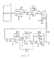
- FIG. 1 is a schematic drawing of an electrical circuit and antenna according to the present invention.
- the present invention utilizes the alternating magnetic field of a vehicle's alternator to determine if a vehicle's engine is operating in the vicinity of the antenna.
- the antenna is preferably in a loop configuration, and more preferably, in a figure-8 configuration. These configurations reduce the noise that the antenna will pick up from other sources.
- the antenna is preferably a plurality of such loops in order to generate a stronger signal. About four figure-8 loops, with a each half of the figure-8 loop being a four foot square has been found to be an acceptable antenna.
- This antenna may be buried in pavement or concrete below a point at which a vehicle is expected to be. Alteratively, the antenna may be attached to a support and placed above that location or placed directly on the pavement.
- the antenna is preferably placed under the position at which the vehicle is expected to be, but may alternatively be placed in an overhead canopy. Placing the antenna below the position at which the vehicle is expected to be is preferred because this results in the antenna be closest to the alternator, and therefore exposed to a stronger electromagnetic field.
- the electromagnetic field created by an operating alternator will be cyclic, with a frequency that varies according to the speed at which the alternator is rotating.
- the frequency of the cycling is the primary distinction between the electromagnetic field created by an alternator compared to electromagnetic fields created by electric motors, electric motors generally creating electromagnetic fields that cycle at higher frequencies.
- Electrical motors may be operating to rotate a radiator or air conditioner fan for a time period after the vehicle's engine is turned off. Also, electrical motors may be used, for example, to open or close windows, or to extend or retract the vehicle's radio antenna. It is therefore significant that frequencies such as those created by such electrical motors be eliminated from the signal from the antenna of the present invention. Additionally, it is important that lower frequencies such as those generated by transmission of 60 Hz power be filtered.
- FIG. 1 a circuit is schematically shown that is capable of filtering high and low frequency noise from the antenna signal, and rectifying and amplifying the remaining signal.
- the antenna A is shown as a figure 8 shaped antenna with two leads extending from the antenna.
- the two leads are preferably transmitted through a coaxial cable to minimize noise picked up by the conduits between the antenna and the remaining portion of the circuit.
- the two leads pass through resistors R1 and R2, which can be 10k ⁇ resistors, and to input amplifier IC1.
- Amplifier IC1 can be a LM324 amplifier available from National Semiconductor, of Santa Clara, California.
- One of the two leads from the antenna is grounded at the input of the input amplifier through a resistor R4, which can be another 10k ⁇ resistor.
- Feedback from the output to the input of the input amplifier is provided through resistor R3, which can be a 10k ⁇ resistor.
- the signal from the input amplifier is passed through a capacitor and resistor pair C1 and R5 which function as a high-pass filter.
- C1 can be a 0.22 uF capacitor and R5 can be a 1k ⁇ resistor.
- the amplified signal from the first high pass filter is passed through a low pass filter, the low pass filter consisting of an amplifier IC2, a resistor R6 and a capacitor C2 is parallel.
- the capacitor can be a 75 nF capacitor and the resistor can be a 1M ⁇ resistor.
- the signal then passes through capacitor C3 which can be a one uF capacitor.
- C3 serves to decouple the following gain control circuitry.
- the signal is then passed through an amplifier, IC3 to provide gain control using feedback from the output signal O, through resistor R8, with the feedback signal grounded through resistor R7.
- IC3 can be a MC3340 amplifier available from Motorola of Phoenix, Arizona.
- R7 and R8 can both be 3.3kn resistors.
- the amplified signal is then passed through another capacitor and resistor pair C5 and R9 that serve as another high pass filter, and another low pass filter consisting of IC4, R10 and C6.
- C5 can be a 0.22 uF capacitor
- R9 can be a 1k ⁇ resistor
- IC4 can be a TL072 amplifier
- R10 can be a 1M ⁇ resistor
- C6 can be a 75 nF capacitor.
- This second set of high pass and low pass filters effectively eliminate noise having frequencies less than about 700 Hz and greater than about 2100 Hz.
- the signal from the second set of high pass and low pass filters is then rectified to generate a signal having a voltage proportional to the integral of the absolute value of the amplified signals passing through the high pass and low pass filters.
- Amplifiers IC5 and IC6, diodes D1 and D2, resistors R11, R12, R13, R14, R15, and R16, and capacitors C7 and C8 provide this rectification.
- the resistors can be, respectively, 20k ⁇ , 20k ⁇ , 200k ⁇ , 100k ⁇ , 1k ⁇ , and 200k ⁇ resistors.
- the amplifiers can be TL072 amplifiers.
- the diodes can both be 1N914 diodes available from International Rectifier, of El Segundo, California.
- the capacitors can be 1 uF and 33 pF capacitors, respectively.
- the elements of this circuit can be sequenced in many different ways, and different numbers of high and low pass filters can be provided depending on the extent to which noise outside of the desired frequency range is to be eliminated. Further, the parameters suggested for the components shown in FIG. 1 are exemplary, and persons of ordinary skill in the art are capable of designing circuits that are functionally similar.
- the antenna of the present invention may have additional functions, such as also being an antenna for a system to determine if a vehicle is located above or in the vicinity of the antenna by a method such as one of those disclosed in U.S. Pat. No. 5,361,064.
- the antenna could therefore be a component of a system effective to determine if a vehicle is present, and if the engine of the vehicle is operating.
- Such a system could sequence refuelling instructions to the operator of the vehicle at a refuelling station and disenable the fuel pump if the vehicle's engine is operating.
- a preferred mode of practicing the present invention is therefore to place the antenna adjacent to a fuel dispenser, and using an output generated by the system of the present invention to disenable the fuel pump.
Landscapes
- Engineering & Computer Science (AREA)
- Mechanical Engineering (AREA)
- Physics & Mathematics (AREA)
- Theoretical Computer Science (AREA)
- Computer Networks & Wireless Communication (AREA)
- Mathematical Physics (AREA)
- General Physics & Mathematics (AREA)
- Combined Controls Of Internal Combustion Engines (AREA)
- Push-Button Switches (AREA)
- Arrangements For Transmission Of Measured Signals (AREA)
- Investigating Or Analyzing Materials By The Use Of Electric Means (AREA)
- Auxiliary Drives, Propulsion Controls, And Safety Devices (AREA)
- Loading And Unloading Of Fuel Tanks Or Ships (AREA)
Abstract
Description
- This invention relates to a method and apparatus for determining if a vehicle with an operating engine is at a particular location.
- Induction loops buried in pavement are typically used to determine if a vehicle is present at above the buried induction loop. These induction loops are most commonly used at traffic signals to trigger a change of the signal when a vehicle approaches or is present at the intersection.
- U.S. Pat. No. 5,361,064 discloses both the typical induction loop design, and the patented improvement to such induction loops. The patented improvement is a compensation for periodic noise caused by such things as nearby power lines. The inductive sensor is driven by an oscillator to produce an oscillator signal having a frequency that is a function of the inductance of the sensor. Fluctuation of the frequency of the oscillator signal caused by the periodic noise is characterized during an initialization phase of operation. During normal measurement phase of operation, the measurement of the oscillator frequency is compensated for periodic noise based upon the prior noise characterization.
- An inductive loop sensor will determine if a sizable mass of metal is located near the induction loop, but cannot differentiate between a vehicle with the engine operating and a vehicle with the engine not operating. Refuelling stations require that the engine of a vehicle not be running when the vehicle is being refuelled, but if the station is a self-service station, it is up to the customer to turn off the ignition of the vehicle. It would be desirable to have a sensor that could automatically determine if the engine of the vehicle is operating. A determination that the vehicle's engine is not operating could be used as a prerequisite for operation of the fuel pump. Many gasoline pumps have visual displays for communication instructions to the customer, and such a visual display could include a notice that the ignition of the vehicle needs to be turned off before the pump can be started. This notice could be triggered by an indication that an operating vehicle engine is present, if such an indication were available.
- A determination that the engine of a vehicle is not operating may be even more important for a refuelling station that is equipped to automatically refuel a vehicle. In an automatic refuelling system, the driver will stay seated in the vehicle as the system proceeds to refuel the vehicle. If the driver does not have to leave the vehicle, it may be more likely that the driver will forget to shut off the ignition, or more likely that the driver will choose to not shut off the ignition in order to remain more comfortable because of continued operation of an air conditioner.
- It could also be desirable to have an indication if the vehicle's engine is operating in an automated refuelling system to discontinue refuelling and remove the fuel dispenser if the driver starts the vehicle's engine with an intention of driving away.
- U.S. Pat. No. 5,337,003 suggests a system to measure the lapsed time an engine is operating by a timer that operates when a sensor placed around an ignition wire detects repeated spark impulses. The engine operation is therefore sensed by the impulse to the ignition, but a sensor clamped around the ignition wire is needed for this determination. An engine operation sensor at a fixed location would have to sense the operation of an engine without contact with the engine itself. Further, such a system will not be applicable to a diesel engine.
- It is therefore an object of the present invention to provide a method and an engine operation sensor capable of sensing if an engine is operating at a predetermined location. It is a further object to provide such a method and sensor that is capable of determining if such an engine is operating whether the engine is a diesel or has an ignition system.
- US-A-4 038 633 discloses an engine operation sensor comprising:
- an antenna comprising a continuous wire formed into at least one loop; and
- a means to determine when the antenna is exposed to an oscillating electromagnetic field having a frequency including the range of 700 to 2100 Hz and of a strength characteristic of a vehicle's alternator operating in the vicinity of the antenna.
-
- US-A-5 249 612 discloses a device for determining whether a detected fuel-receiving container is of a suitable type by generating a field, such as an electro-magnetic field, and measuring the reaction of the container to the field. Unless the container is determined to be suitable the device blocks the dispensing of fuel.
- According to a first aspect of the present invention there is provided an engine operation sensor comprising:
- an antenna comprising a continuous wire formed into at least one loop;
- a determining means to determine when the antenna is exposed to an oscillating electromagnetic field having a frequency between about 700 and about 2100 Hz of a strength characteristic of a vehicle's alternator operating in the vicinity of the antenna; and
- a means to generate a signal when it is determined that the antenna is exposed to an oscillating electromagnetic field having a frequency between about 700 and 2100 Hz of a strength characteristic of a vehicle's alternator operating in the vicinity of the antenna, wherein the signal is used as an input into a logic system that requires that the signal not be generated in order for a refuelling system to refuel a vehicle in the vicinity of the antenna.
-
- According to a second aspect of the present invention there is provided a method to determine if a vehicle's engine is operating at a particular location, the method comprising the steps of:
- providing an antenna comprising an insulated continuous wire formed into at least one loop at the particular location;
- determining when a vehicle's engine is operating at that particular location by determining when the antenna is exposed to an oscillating electromagnetic field having a frequency between about 700 and about 2100 Hz of a strength characteristic of a vehicle's alternator operating in the vicinity of the antenna; and
- generating a signal when it is determined that the antenna is exposed to an oscillating electromagnetic field having a frequency between about 700 and about 2100 Hz of a strength characteristic of a vehicle's alternator operating in the vicinity of the antenna, wherein the signal is an input into a logic system that requires that the signal not be generated in order for a refuelling system to refuel a vehicle in the vicinity of the antenna.
-
- The means to determine when the antenna is exposed to an oscillating electromagnetic field having a frequency between about 700 and about 2100 Hz of a strength characteristic of a vehicle's alternator operating in the vicinity of the antenna is preferably a combination of at least one high-pass filter, and at least one low-pass filter, the two filters capable of filtering antenna output of frequencies greater than about 2100 Hz and frequencies less than about 700 Hz. The antenna is preferably a figure eight loop antenna placed in pavement below the location at which the vehicle is expected to be.
- The sensor of the present invention is particularly applicable as an input to disable a fuel pump at a refuelling station when engine operation is detected.
- FIG. 1 is a schematic drawing of an electrical circuit and antenna according to the present invention.
- The present invention utilizes the alternating magnetic field of a vehicle's alternator to determine if a vehicle's engine is operating in the vicinity of the antenna. The antenna is preferably in a loop configuration, and more preferably, in a figure-8 configuration. These configurations reduce the noise that the antenna will pick up from other sources. The antenna is preferably a plurality of such loops in order to generate a stronger signal. About four figure-8 loops, with a each half of the figure-8 loop being a four foot square has been found to be an acceptable antenna. This antenna may be buried in pavement or concrete below a point at which a vehicle is expected to be. Alteratively, the antenna may be attached to a support and placed above that location or placed directly on the pavement. The antenna is preferably placed under the position at which the vehicle is expected to be, but may alternatively be placed in an overhead canopy. Placing the antenna below the position at which the vehicle is expected to be is preferred because this results in the antenna be closest to the alternator, and therefore exposed to a stronger electromagnetic field.
- The electromagnetic field created by an operating alternator will be cyclic, with a frequency that varies according to the speed at which the alternator is rotating. The frequency of the cycling is the primary distinction between the electromagnetic field created by an alternator compared to electromagnetic fields created by electric motors, electric motors generally creating electromagnetic fields that cycle at higher frequencies. Electrical motors may be operating to rotate a radiator or air conditioner fan for a time period after the vehicle's engine is turned off. Also, electrical motors may be used, for example, to open or close windows, or to extend or retract the vehicle's radio antenna. It is therefore significant that frequencies such as those created by such electrical motors be eliminated from the signal from the antenna of the present invention. Additionally, it is important that lower frequencies such as those generated by transmission of 60 Hz power be filtered.
- Referring now to FIG. 1, a circuit is schematically shown that is capable of filtering high and low frequency noise from the antenna signal, and rectifying and amplifying the remaining signal. The antenna A is shown as a figure 8 shaped antenna with two leads extending from the antenna. The two leads are preferably transmitted through a coaxial cable to minimize noise picked up by the conduits between the antenna and the remaining portion of the circuit. The two leads pass through resistors R1 and R2, which can be 10kΩ resistors, and to input amplifier IC1. Amplifier IC1 can be a LM324 amplifier available from National Semiconductor, of Santa Clara, California.
- One of the two leads from the antenna is grounded at the input of the input amplifier through a resistor R4, which can be another 10kΩ resistor. Feedback from the output to the input of the input amplifier is provided through resistor R3, which can be a 10kΩ resistor. The signal from the input amplifier is passed through a capacitor and resistor pair C1 and R5 which function as a high-pass filter. C1 can be a 0.22 uF capacitor and R5 can be a 1kΩ resistor.
- The amplified signal from the first high pass filter is passed through a low pass filter, the low pass filter consisting of an amplifier IC2, a resistor R6 and a capacitor C2 is parallel. The capacitor can be a 75 nF capacitor and the resistor can be a 1MΩ resistor.
- The signal then passes through capacitor C3 which can be a one uF capacitor. C3 serves to decouple the following gain control circuitry.
- The signal is then passed through an amplifier, IC3 to provide gain control using feedback from the output signal O, through resistor R8, with the feedback signal grounded through resistor R7. IC3 can be a MC3340 amplifier available from Motorola of Phoenix, Arizona. R7 and R8 can both be 3.3kn resistors.
- The amplified signal is then passed through another capacitor and resistor pair C5 and R9 that serve as another high pass filter, and another low pass filter consisting of IC4, R10 and C6. C5 can be a 0.22 uF capacitor, R9 can be a 1kΩ resistor, IC4 can be a TL072 amplifier, R10 can be a 1MΩ resistor and C6 can be a 75 nF capacitor.
- This second set of high pass and low pass filters effectively eliminate noise having frequencies less than about 700 Hz and greater than about 2100 Hz.
- The signal from the second set of high pass and low pass filters is then rectified to generate a signal having a voltage proportional to the integral of the absolute value of the amplified signals passing through the high pass and low pass filters. Amplifiers IC5 and IC6, diodes D1 and D2, resistors R11, R12, R13, R14, R15, and R16, and capacitors C7 and C8 provide this rectification. The resistors can be, respectively, 20kΩ, 20kΩ, 200kΩ, 100kΩ, 1kΩ, and 200kΩ resistors. The amplifiers can be TL072 amplifiers. The diodes can both be 1N914 diodes available from International Rectifier, of El Segundo, California. The capacitors can be 1 uF and 33 pF capacitors, respectively.
- The elements of this circuit can be sequenced in many different ways, and different numbers of high and low pass filters can be provided depending on the extent to which noise outside of the desired frequency range is to be eliminated. Further, the parameters suggested for the components shown in FIG. 1 are exemplary, and persons of ordinary skill in the art are capable of designing circuits that are functionally similar.
- The antenna of the present invention may have additional functions, such as also being an antenna for a system to determine if a vehicle is located above or in the vicinity of the antenna by a method such as one of those disclosed in U.S. Pat. No. 5,361,064. The antenna could therefore be a component of a system effective to determine if a vehicle is present, and if the engine of the vehicle is operating. Such a system could sequence refuelling instructions to the operator of the vehicle at a refuelling station and disenable the fuel pump if the vehicle's engine is operating. A preferred mode of practicing the present invention is therefore to place the antenna adjacent to a fuel dispenser, and using an output generated by the system of the present invention to disenable the fuel pump.
- The preceding description of the invention is exemplary, and reference to the following claims is made to determine the full scope of the present invention.
Claims (14)
- An engine operation sensor comprising:an antenna comprising a continuous wire formed into at least one loop;a determining means to determine when the antenna is exposed to an oscillating electromagnetic field having a frequency between about 700 and about 2100 Hz of a strength characteristic of a vehicle's alternator operating in the vicinity of the antenna; anda means to generate a signal when it is determined that the antenna is exposed to an oscillating electromagnetic field having a frequency between about 700 and about 2100 Hz of a strength characteristic of a vehicle's alternator operating in the vicinity of the antenna, wherein the signal is used as an input into a logic system that requires that the signal not be generated in order for a refuelling system to refuel a vehicle in the vicinity of the antenna.
- The sensor of claim 1, wherein the determining means comprises at least one high pass filter and at least one low pass filter.
- The sensor of claim 1, wherein the determining means comprises a plurality of high-pass filters, and a plurality of low-pass filters.
- The sensor of any one of the preceding claims, wherein the antenna is a figure of eight loop antenna placed in pavement below the location at which the vehicle is expected to be.
- The sensor of any one of the preceding claims, wherein the antenna is placed in pavement adjacent to a fuel dispenser.
- The sensor of any one of the preceding claims, wherein the determining means further comprises a precision rectifier to convert the alternating signal from the antenna to a direct current voltage differential.
- The sensor of claim 6, wherein the determining means further comprises an amplifier effective to amplify the differential potential between leads of the antenna.
- A method to determine if a vehicle's engine is operating at a particular location, the method comprising the steps of:providing an antenna comprising an insulated continuous wire formed into at least one loop at the particular location;determining when a vehicle's engine is operating at that particular location by determining when the antenna is exposed to an oscillating electromagnetic field having a frequency between about 700 and about 2100 Hz of a strength characteristic of a vehicle's alternator operating in the vicinity of the antenna; andgenerating a signal when it is determined that the antenna is exposed to an oscillating electromagnetic field having a frequency between about 700 and about 2100 Hz of a strength characteristic of a vehicle's alternator operating in the vicinity of the antenna, wherein the signal is an input into a logic system that requires that the signal not be generated in order for a refuelling system to refuel a vehicle in the vicinity of the antenna.
- The method claim 8, wherein the determination step comprises passing a signal from the antenna through at least one high pass filter and at least one low pass filter.
- The method of claim 8, wherein the determining step comprises passing a signal from the antenna through a plurality of high-pass filters, and a plurality of low-pass filters, the high pass filters being effective to essentially eliminate electrical noise having a frequency less than about 700 Hz and the low pass filters being effective to essentially eliminate electrical noise having a frequency greater than about 2100 Hz.
- The method of any one of claims 8 to 10, wherein the antenna is a figure of eight loop antenna placed in pavement below the location at which the vehicle is expected to be.
- The method of any one of claims 8 to 11, wherein the antenna is placed in pavement adjacent to a fuel dispenser.
- The method of any one of claims 8 to 12, wherein the determining step comprises rectifying a signal from the antenna to convert the alternating signal from the antenna to a direct current voltage differential, a direct current differential above a threshold level being indicative of an operating vehicle engine.
- The method of claim 13, wherein the determining step further comprises amplifying the differential potential between leads of the antenna.
Applications Claiming Priority (3)
| Application Number | Priority Date | Filing Date | Title |
|---|---|---|---|
| US461279 | 1995-06-05 | ||
| US08/461,279 US5705999A (en) | 1995-06-05 | 1995-06-05 | Engine operation detection |
| PCT/US1996/007860 WO1996039688A1 (en) | 1995-06-05 | 1996-05-29 | Engine operation detection |
Publications (2)
| Publication Number | Publication Date |
|---|---|
| EP0830662A1 EP0830662A1 (en) | 1998-03-25 |
| EP0830662B1 true EP0830662B1 (en) | 1999-10-20 |
Family
ID=23831924
Family Applications (1)
| Application Number | Title | Priority Date | Filing Date |
|---|---|---|---|
| EP96916709A Expired - Lifetime EP0830662B1 (en) | 1995-06-05 | 1996-05-29 | Engine operation detection |
Country Status (9)
| Country | Link |
|---|---|
| US (1) | US5705999A (en) |
| EP (1) | EP0830662B1 (en) |
| JP (1) | JP2001517180A (en) |
| AT (1) | ATE185917T1 (en) |
| AU (1) | AU704428B2 (en) |
| CA (1) | CA2223374A1 (en) |
| DE (1) | DE69604803T2 (en) |
| ES (1) | ES2140098T3 (en) |
| WO (1) | WO1996039688A1 (en) |
Families Citing this family (9)
| Publication number | Priority date | Publication date | Assignee | Title |
|---|---|---|---|---|
| US6611210B2 (en) * | 1996-12-03 | 2003-08-26 | Inductive Signature Technologies, Inc. | Automotive vehicle classification and identification by inductive signature |
| SE512518C2 (en) * | 1998-05-07 | 2000-03-27 | Autofill Patent Ab | Device for automatic refueling of vehicles |
| CN1319726C (en) | 1999-12-01 | 2007-06-06 | 倍耐力轮胎公司 | Plant for producing tyres of different types simultaneously |
| US7082406B1 (en) | 2000-06-22 | 2006-07-25 | Gilbarco Inc. | Multi-stage accounting system for a fueling environment |
| US7634341B2 (en) * | 2001-03-07 | 2009-12-15 | 1138037 Ontario Ltd. (“Alirt”) | Detecting device and method of using same |
| US20060178586A1 (en) * | 2005-02-07 | 2006-08-10 | Dobak John D Iii | Devices and methods for accelerometer-based characterization of cardiac function and identification of LV target pacing zones |
| US20080291055A1 (en) * | 2007-05-23 | 2008-11-27 | Harrington Nathan J | Method and system for vehicle traffic monitoring based on the detection of a characteristic radio frequency |
| US20110267222A1 (en) * | 2010-04-30 | 2011-11-03 | Murray Craig | Location detection methods and systems |
| US9051928B2 (en) * | 2011-05-09 | 2015-06-09 | Ahmad I. S. I. Al-Jafar | Safety device for preventing delivery of fuel to a motor vehicle with a running engine |
Family Cites Families (12)
| Publication number | Priority date | Publication date | Assignee | Title |
|---|---|---|---|---|
| US4038633A (en) * | 1973-08-22 | 1977-07-26 | King Frederick N | Detection system for automobiles and other motor-driven objects |
| US4179744A (en) * | 1978-03-02 | 1979-12-18 | Magtronics Incorporated | Method and apparatus for analyzing performance of electric-traction-motor powered vehicles and electrical operating components thereof |
| AU583785B2 (en) * | 1982-12-02 | 1989-05-11 | Peek Traffic Limited | Improved environmental tracking in inductance loop vehicle detection systems |
| GB8421715D0 (en) * | 1984-08-28 | 1984-10-03 | Buttemer D A | Loop detector |
| DE3632316A1 (en) * | 1986-09-23 | 1988-03-31 | Siemens Ag | VEHICLE DETECTOR |
| US5198811A (en) * | 1987-05-08 | 1993-03-30 | Detector Systems, Inc. | Vehicle communication system using existing roadway loops wherein the physical integrity of the loop is kept intact |
| US5361064A (en) * | 1991-06-17 | 1994-11-01 | Minnesota Mining And Manufacturing Company | Vehicle detector with power main noise compensation |
| JP2549248Y2 (en) * | 1991-08-30 | 1997-09-30 | 富士重工業株式会社 | Safety circuit for vehicle fuel supply system |
| US5249612A (en) * | 1992-07-24 | 1993-10-05 | Bti, Inc. | Apparatus and methods for controlling fluid dispensing |
| US5455768A (en) * | 1992-11-06 | 1995-10-03 | Safetran Traffic Systems, Inc. | System for determining vehicle speed and presence |
| US5337003A (en) * | 1992-12-28 | 1994-08-09 | Carmichael Edward W | Self-contained, clip-on engine operating time log |
| US5512891A (en) * | 1994-05-04 | 1996-04-30 | H. M. Electronics, Inc. | Drive-up station vehicle detection system and method of using same |
-
1995
- 1995-06-05 US US08/461,279 patent/US5705999A/en not_active Expired - Fee Related
-
1996
- 1996-05-29 WO PCT/US1996/007860 patent/WO1996039688A1/en not_active Ceased
- 1996-05-29 JP JP50078897A patent/JP2001517180A/en active Pending
- 1996-05-29 AT AT96916709T patent/ATE185917T1/en not_active IP Right Cessation
- 1996-05-29 DE DE69604803T patent/DE69604803T2/en not_active Expired - Fee Related
- 1996-05-29 EP EP96916709A patent/EP0830662B1/en not_active Expired - Lifetime
- 1996-05-29 ES ES96916709T patent/ES2140098T3/en not_active Expired - Lifetime
- 1996-05-29 CA CA002223374A patent/CA2223374A1/en not_active Abandoned
- 1996-05-29 AU AU59378/96A patent/AU704428B2/en not_active Ceased
Also Published As
| Publication number | Publication date |
|---|---|
| DE69604803T2 (en) | 2000-05-18 |
| EP0830662A1 (en) | 1998-03-25 |
| ES2140098T3 (en) | 2000-02-16 |
| US5705999A (en) | 1998-01-06 |
| JP2001517180A (en) | 2001-10-02 |
| ATE185917T1 (en) | 1999-11-15 |
| DE69604803D1 (en) | 1999-11-25 |
| AU5937896A (en) | 1996-12-24 |
| CA2223374A1 (en) | 1996-12-12 |
| WO1996039688A1 (en) | 1996-12-12 |
| AU704428B2 (en) | 1999-04-22 |
Similar Documents
| Publication | Publication Date | Title |
|---|---|---|
| US5705999A (en) | Engine operation detection | |
| US5291208A (en) | Incipient lightning detection and device protection | |
| EP0622642B1 (en) | An object detecting device | |
| US5521603A (en) | Incipient lightning detection and device protection | |
| EP3799259A1 (en) | Apparatus, device and method for detecting metal foreign matter in wireless charging system | |
| EP0053103B1 (en) | Circuit for detecting and signalling failure and irregular operation of a charging device for batteries | |
| US9553636B2 (en) | Contactless electricity supply device with foreign object detector | |
| CA1249124A (en) | Flux-gate sensor electrical drive method and circuit | |
| US5654686A (en) | Electronic vehicle theft detection system employing a magnetic field sensor | |
| US4491785A (en) | Tracing electrical conductors by high-frequency loading and improved signal detection | |
| US4785294A (en) | Static monitoring system | |
| EP1265337B1 (en) | Abnormality detection apparatus of vehicle AC generator | |
| JPH0356859A (en) | Method of detecting number of revolutions of internal-combustion engine | |
| US20030042874A1 (en) | Voltage sensing for automotive voltage regulator | |
| US4038633A (en) | Detection system for automobiles and other motor-driven objects | |
| EP0735641B1 (en) | Charge control system for use in internal combustion engine | |
| US3825889A (en) | Vehicle detection system | |
| US4037194A (en) | Current sensing alarm circuit for a motor vehicle | |
| US3714626A (en) | Vehicle detection system | |
| EP0448065B1 (en) | A battery-recharging system for a motor vehicle | |
| GB2191591A (en) | Earth monitoring | |
| CN208035985U (en) | Parking space manages system | |
| CN210155245U (en) | Single-phase earth fault locator of distribution network | |
| EP0485190A2 (en) | Security systems | |
| JPS61203737A (en) | Communication system between vehicles on road |
Legal Events
| Date | Code | Title | Description |
|---|---|---|---|
| PUAI | Public reference made under article 153(3) epc to a published international application that has entered the european phase |
Free format text: ORIGINAL CODE: 0009012 |
|
| 17P | Request for examination filed |
Effective date: 19971201 |
|
| AK | Designated contracting states |
Kind code of ref document: A1 Designated state(s): AT BE CH DE DK ES FR GB GR IT LI NL SE |
|
| GRAG | Despatch of communication of intention to grant |
Free format text: ORIGINAL CODE: EPIDOS AGRA |
|
| 17Q | First examination report despatched |
Effective date: 19990226 |
|
| GRAG | Despatch of communication of intention to grant |
Free format text: ORIGINAL CODE: EPIDOS AGRA |
|
| GRAH | Despatch of communication of intention to grant a patent |
Free format text: ORIGINAL CODE: EPIDOS IGRA |
|
| GRAH | Despatch of communication of intention to grant a patent |
Free format text: ORIGINAL CODE: EPIDOS IGRA |
|
| GRAA | (expected) grant |
Free format text: ORIGINAL CODE: 0009210 |
|
| AK | Designated contracting states |
Kind code of ref document: B1 Designated state(s): AT BE CH DE DK ES FR GB GR IT LI NL SE |
|
| PG25 | Lapsed in a contracting state [announced via postgrant information from national office to epo] |
Ref country code: SE Free format text: THE PATENT HAS BEEN ANNULLED BY A DECISION OF A NATIONAL AUTHORITY Effective date: 19991020 Ref country code: LI Free format text: LAPSE BECAUSE OF FAILURE TO SUBMIT A TRANSLATION OF THE DESCRIPTION OR TO PAY THE FEE WITHIN THE PRESCRIBED TIME-LIMIT Effective date: 19991020 Ref country code: GR Free format text: LAPSE BECAUSE OF NON-PAYMENT OF DUE FEES Effective date: 19991020 Ref country code: CH Free format text: LAPSE BECAUSE OF FAILURE TO SUBMIT A TRANSLATION OF THE DESCRIPTION OR TO PAY THE FEE WITHIN THE PRESCRIBED TIME-LIMIT Effective date: 19991020 Ref country code: BE Free format text: LAPSE BECAUSE OF FAILURE TO SUBMIT A TRANSLATION OF THE DESCRIPTION OR TO PAY THE FEE WITHIN THE PRESCRIBED TIME-LIMIT Effective date: 19991020 Ref country code: AT Free format text: LAPSE BECAUSE OF FAILURE TO SUBMIT A TRANSLATION OF THE DESCRIPTION OR TO PAY THE FEE WITHIN THE PRESCRIBED TIME-LIMIT Effective date: 19991020 |
|
| REF | Corresponds to: |
Ref document number: 185917 Country of ref document: AT Date of ref document: 19991115 Kind code of ref document: T |
|
| ET | Fr: translation filed | ||
| REG | Reference to a national code |
Ref country code: CH Ref legal event code: EP |
|
| REF | Corresponds to: |
Ref document number: 69604803 Country of ref document: DE Date of ref document: 19991125 |
|
| ITF | It: translation for a ep patent filed | ||
| PG25 | Lapsed in a contracting state [announced via postgrant information from national office to epo] |
Ref country code: DK Free format text: LAPSE BECAUSE OF FAILURE TO SUBMIT A TRANSLATION OF THE DESCRIPTION OR TO PAY THE FEE WITHIN THE PRESCRIBED TIME-LIMIT Effective date: 20000120 |
|
| REG | Reference to a national code |
Ref country code: ES Ref legal event code: FG2A Ref document number: 2140098 Country of ref document: ES Kind code of ref document: T3 |
|
| REG | Reference to a national code |
Ref country code: CH Ref legal event code: PL |
|
| PLBE | No opposition filed within time limit |
Free format text: ORIGINAL CODE: 0009261 |
|
| STAA | Information on the status of an ep patent application or granted ep patent |
Free format text: STATUS: NO OPPOSITION FILED WITHIN TIME LIMIT |
|
| 26N | No opposition filed | ||
| REG | Reference to a national code |
Ref country code: GB Ref legal event code: IF02 |
|
| PGFP | Annual fee paid to national office [announced via postgrant information from national office to epo] |
Ref country code: FR Payment date: 20020508 Year of fee payment: 7 |
|
| PGFP | Annual fee paid to national office [announced via postgrant information from national office to epo] |
Ref country code: ES Payment date: 20020522 Year of fee payment: 7 |
|
| PGFP | Annual fee paid to national office [announced via postgrant information from national office to epo] |
Ref country code: NL Payment date: 20020529 Year of fee payment: 7 Ref country code: GB Payment date: 20020529 Year of fee payment: 7 |
|
| PGFP | Annual fee paid to national office [announced via postgrant information from national office to epo] |
Ref country code: DE Payment date: 20020610 Year of fee payment: 7 |
|
| PG25 | Lapsed in a contracting state [announced via postgrant information from national office to epo] |
Ref country code: GB Free format text: LAPSE BECAUSE OF NON-PAYMENT OF DUE FEES Effective date: 20030529 |
|
| PG25 | Lapsed in a contracting state [announced via postgrant information from national office to epo] |
Ref country code: ES Free format text: LAPSE BECAUSE OF NON-PAYMENT OF DUE FEES Effective date: 20030530 |
|
| PG25 | Lapsed in a contracting state [announced via postgrant information from national office to epo] |
Ref country code: NL Free format text: LAPSE BECAUSE OF NON-PAYMENT OF DUE FEES Effective date: 20031201 |
|
| PG25 | Lapsed in a contracting state [announced via postgrant information from national office to epo] |
Ref country code: DE Free format text: LAPSE BECAUSE OF NON-PAYMENT OF DUE FEES Effective date: 20031202 |
|
| GBPC | Gb: european patent ceased through non-payment of renewal fee |
Effective date: 20030529 |
|
| PG25 | Lapsed in a contracting state [announced via postgrant information from national office to epo] |
Ref country code: FR Free format text: LAPSE BECAUSE OF NON-PAYMENT OF DUE FEES Effective date: 20040130 |
|
| NLV4 | Nl: lapsed or anulled due to non-payment of the annual fee |
Effective date: 20031201 |
|
| REG | Reference to a national code |
Ref country code: FR Ref legal event code: ST |
|
| REG | Reference to a national code |
Ref country code: ES Ref legal event code: FD2A Effective date: 20030530 |
|
| PG25 | Lapsed in a contracting state [announced via postgrant information from national office to epo] |
Ref country code: IT Free format text: LAPSE BECAUSE OF NON-PAYMENT OF DUE FEES;WARNING: LAPSES OF ITALIAN PATENTS WITH EFFECTIVE DATE BEFORE 2007 MAY HAVE OCCURRED AT ANY TIME BEFORE 2007. THE CORRECT EFFECTIVE DATE MAY BE DIFFERENT FROM THE ONE RECORDED. Effective date: 20050529 |