EP0830266B1 - Obstacle detection system for vehicles moving in reverse - Google Patents
Obstacle detection system for vehicles moving in reverse Download PDFInfo
- Publication number
- EP0830266B1 EP0830266B1 EP96922185A EP96922185A EP0830266B1 EP 0830266 B1 EP0830266 B1 EP 0830266B1 EP 96922185 A EP96922185 A EP 96922185A EP 96922185 A EP96922185 A EP 96922185A EP 0830266 B1 EP0830266 B1 EP 0830266B1
- Authority
- EP
- European Patent Office
- Prior art keywords
- vehicle
- detection system
- obstacle
- driver
- obstacle detection
- Prior art date
- Legal status (The legal status is an assumption and is not a legal conclusion. Google has not performed a legal analysis and makes no representation as to the accuracy of the status listed.)
- Expired - Lifetime
Links
- 238000001514 detection method Methods 0.000 title claims abstract description 110
- 230000000007 visual effect Effects 0.000 claims abstract description 22
- 230000011664 signaling Effects 0.000 claims description 14
- 230000004044 response Effects 0.000 claims description 9
- 238000012216 screening Methods 0.000 claims description 4
- 238000004422 calculation algorithm Methods 0.000 description 10
- 238000004364 calculation method Methods 0.000 description 5
- 238000005259 measurement Methods 0.000 description 5
- 230000003287 optical effect Effects 0.000 description 5
- 230000006378 damage Effects 0.000 description 4
- 238000010586 diagram Methods 0.000 description 4
- 239000011159 matrix material Substances 0.000 description 4
- 238000000034 method Methods 0.000 description 4
- 230000002411 adverse Effects 0.000 description 3
- 230000006870 function Effects 0.000 description 3
- 230000008054 signal transmission Effects 0.000 description 3
- 238000012360 testing method Methods 0.000 description 3
- 238000002604 ultrasonography Methods 0.000 description 3
- 238000003491 array Methods 0.000 description 2
- 239000000428 dust Substances 0.000 description 2
- 238000012544 monitoring process Methods 0.000 description 2
- 208000027418 Wounds and injury Diseases 0.000 description 1
- 230000003213 activating effect Effects 0.000 description 1
- 230000006978 adaptation Effects 0.000 description 1
- 230000005540 biological transmission Effects 0.000 description 1
- 230000008859 change Effects 0.000 description 1
- 238000004590 computer program Methods 0.000 description 1
- 238000002405 diagnostic procedure Methods 0.000 description 1
- 239000006185 dispersion Substances 0.000 description 1
- 230000009977 dual effect Effects 0.000 description 1
- 230000004438 eyesight Effects 0.000 description 1
- 230000012447 hatching Effects 0.000 description 1
- 230000001771 impaired effect Effects 0.000 description 1
- 208000014674 injury Diseases 0.000 description 1
- 230000001788 irregular Effects 0.000 description 1
- 238000012986 modification Methods 0.000 description 1
- 230000004048 modification Effects 0.000 description 1
- 230000004297 night vision Effects 0.000 description 1
- 230000008520 organization Effects 0.000 description 1
Images




Classifications
-
- G—PHYSICS
- G01—MEASURING; TESTING
- G01S—RADIO DIRECTION-FINDING; RADIO NAVIGATION; DETERMINING DISTANCE OR VELOCITY BY USE OF RADIO WAVES; LOCATING OR PRESENCE-DETECTING BY USE OF THE REFLECTION OR RERADIATION OF RADIO WAVES; ANALOGOUS ARRANGEMENTS USING OTHER WAVES
- G01S15/00—Systems using the reflection or reradiation of acoustic waves, e.g. sonar systems
- G01S15/88—Sonar systems specially adapted for specific applications
- G01S15/93—Sonar systems specially adapted for specific applications for anti-collision purposes
- G01S15/931—Sonar systems specially adapted for specific applications for anti-collision purposes of land vehicles
-
- B—PERFORMING OPERATIONS; TRANSPORTING
- B60—VEHICLES IN GENERAL
- B60Q—ARRANGEMENT OF SIGNALLING OR LIGHTING DEVICES, THE MOUNTING OR SUPPORTING THEREOF OR CIRCUITS THEREFOR, FOR VEHICLES IN GENERAL
- B60Q9/00—Arrangement or adaptation of signal devices not provided for in one of main groups B60Q1/00 - B60Q7/00, e.g. haptic signalling
- B60Q9/002—Arrangement or adaptation of signal devices not provided for in one of main groups B60Q1/00 - B60Q7/00, e.g. haptic signalling for parking purposes, e.g. for warning the driver that his vehicle has contacted or is about to contact an obstacle
- B60Q9/007—Arrangement or adaptation of signal devices not provided for in one of main groups B60Q1/00 - B60Q7/00, e.g. haptic signalling for parking purposes, e.g. for warning the driver that his vehicle has contacted or is about to contact an obstacle providing information about the distance to an obstacle, e.g. varying sound
-
- G—PHYSICS
- G01—MEASURING; TESTING
- G01S—RADIO DIRECTION-FINDING; RADIO NAVIGATION; DETERMINING DISTANCE OR VELOCITY BY USE OF RADIO WAVES; LOCATING OR PRESENCE-DETECTING BY USE OF THE REFLECTION OR RERADIATION OF RADIO WAVES; ANALOGOUS ARRANGEMENTS USING OTHER WAVES
- G01S15/00—Systems using the reflection or reradiation of acoustic waves, e.g. sonar systems
- G01S15/88—Sonar systems specially adapted for specific applications
- G01S15/93—Sonar systems specially adapted for specific applications for anti-collision purposes
- G01S15/931—Sonar systems specially adapted for specific applications for anti-collision purposes of land vehicles
- G01S2015/937—Sonar systems specially adapted for specific applications for anti-collision purposes of land vehicles sensor installation details
- G01S2015/939—Sonar systems specially adapted for specific applications for anti-collision purposes of land vehicles sensor installation details vertical stacking of sensors, e.g. to enable obstacle height determination
-
- Y—GENERAL TAGGING OF NEW TECHNOLOGICAL DEVELOPMENTS; GENERAL TAGGING OF CROSS-SECTIONAL TECHNOLOGIES SPANNING OVER SEVERAL SECTIONS OF THE IPC; TECHNICAL SUBJECTS COVERED BY FORMER USPC CROSS-REFERENCE ART COLLECTIONS [XRACs] AND DIGESTS
- Y10—TECHNICAL SUBJECTS COVERED BY FORMER USPC
- Y10S—TECHNICAL SUBJECTS COVERED BY FORMER USPC CROSS-REFERENCE ART COLLECTIONS [XRACs] AND DIGESTS
- Y10S367/00—Communications, electrical: acoustic wave systems and devices
- Y10S367/909—Collision avoidance
Definitions
- the present invention relates to an obstacle detection system according to the preamble of claim 1.
- An obstacle detection system of this kind is known from document US-A-5,214,408.
- U.S. Patent Nos. 5,214,408 to Asayama and 5,304,980 to Maekawa disclose target detection systems using light sensitive image sensors for optically sensing two image signals from an object, comparing the two signals and calculating the distance to the object based on the deviation between the images using triangulation.
- the systems utilize dual lenses mounted at the front of the vehicle to measure the distance from a leading vehicle by comparing the two images received by each of the two lenses.
- An infrared light generating means is also provided for projecting infrared light toward the object when atmospheric light is insufficient.
- Some of the problems associated with these image sensor systems include poor resolution at very close distances which makes it unsuitable for backing-up applications; poor performance in situations of impaired visibility such as inclement weather, dust, smog and especially fog; the susceptibility of the lenses to damage or ineffectiveness due to dirt, dust, snow or rain; and the relative expense of such systems.
- Video systems which consist of a camera mounted on the upper rear portion of the vehicle, and a monitor on the instrument panel or above the dashboard inside the vehicle.
- Video systems came into use in several special applications such as buses, airport apron vehicles, and the like. These devices have many disadvantages such as poor night vision, their inability to gauge the distance between the vehicle and the obstacle, and severe safety problems associated with the driver being distracted and preoccupied trying to observe the video monitor and use the side view mirrors while moving the vehicle in reverse.
- Yet another optical system is a distance measurement system using lasers. These systems also suffer from the disadvantage of poor performance under adverse weather conditions, and are also unable to measure close distances such as those under three meters.
- Conductivity measurement systems as that disclosed in British Patent No. UK 2,266,397 are based on changes in the capacitance in the environment and are generally effective for a very short range, on the order of approximately 30cm.
- the conductive strip must be mounted across the full width of the rear of the vehicle, and adverse weather conditions such as rain and snow may change the conductive field which may result in false alarms.
- Ultrasonic systems are cited by industry experts as the preferred technology including ISO Technical Report ISO/TR 12155 published by the International Organization for Standardization.
- Various ultrasonic systems have been proposed, and include those employing basic ultrasonic signal transmitting and receiving circuitry.
- the technology is suitable for all weather and visibility circumstances, and provides the optimal performance in short distance measurement and target detection due to the lower speed of sound.
- a signal is transmitted and the echo is deflected to the receiver providing an indication of presence and distance of a target based on the speed of sound.
- the disadvantages of these devices in general include an inability to measure at very short distances due to cross-talk between the transmitter and receiver, and poor area coverage and the inability to detect targets of irregular shapes and/or sizes.
- FIG. 9 is a schematic representation of the angular configuration of the watching areas in which primed reference numerals are used. It is a top view of a portion of vehicle 10' having three obstacle detectors 12', 14' and 16' mounted in parallel, and an obstacle 18'.
- Each detector has an angular coverage area, and it can be seen that some areas close to the detectors remain uncovered. Those uncovered areas are labeled 20' and 22' and are indicated with hatching. Widening the angle of coverage to address this problem results in a significant decrease in the signal strength thereby reducing the distance that can be covered.
- a further example is shown in GB-A-2131642 to Daimler Benz and Siemens that discloses a different method for detection whereby the detection area is divided into 49 cells referred to as a "memory matrix".
- the detection system uses unpaired transmitters and receivers to determine whether an obstacle is present in a cell of the memory matrix. The presence of an obstacle is indicated when the system decodes a positive or binary ONE in a cell of the memory matrix. Thus only the presence of an obstacle corresponding to its location in the matrix is indicated, but not the distance.
- the disclosed system simply sends a signal from one side and receives and a reflected signal which allows it to locate the cell in which the obstacle is located.
- FIG. 9 Another problem with conventional systems such as that pictured in FIG. 9 is that the use of transducers in parallel relation to one another may miss certain angular hazards due to deflection of the transmitted signal away from any receivers.
- two signals 24a' and 26a' are transmitted from detector 12' toward obstacle 18' which has an angular shape or orientation. Due to the shape of obstacle 18', deflected signals 24b' and 26b' travel away from any receiving sensors of the detectors and obstacle 18' is not detected.
- an electronic obstacle detection system for guiding and warning a motorist of obstacles in a detection area while backing-up having the features of claim 1.
- the main components of the system include a pair of sensor clusters to be affixed to the rear of the vehicle, a pair of exterior visual indicators, and an audio-visual indicator located in the vehicle.
- Each of the sensor clusters are encased in a housing which is configured to provide complete detection area coverage of transmitted and received signals.
- the system is preferably powered by power source within the vehicle.
- the present system detects objects in at least three zones of a detection area which refers to the area behind the vehicle within which the system can detect obstacles: a close collision zone directly behind the vehicle, a warning zone further behind the vehicle, and a pre-warning zone behind the warning zone. Due to the configuration of the sensor clusters and their position on the back of the vehicle, there are no gaps in coverage and the entire horizontal detection area is covered.
- the present system allows for operation of the sensor clusters in both monostatic and bistatic modes thereby enabling the system to receive return signals deflected from odd shaped hazards which may have been missed by conventional systems.
- the term "monostatic” in this context refers to the transmission of a signal and reception of the return signal by the same sensor pair; and the term “bistatic” refers to the transmission of a signal by one sensor and reception of the return signal by a non-paired receiver.
- the detection system of the present invention is not susceptible to "dead" areas or gaps in coverage between sensors, and can detect oddly shaped hazards, particularly angular ones which tend to deflect transmitted signals away from receivers of conventional systems. Redundancy is build into the system so that damage to or failure of any individual sensor does not impair the overall functioning of the system.
- the present system is not affected by adverse weather conditions or limited visibility.
- the system can be installed easily to most vehicles regardless of the rear configuration and the locations of the sensor clusters do not affect the operation of lift gates on most trucks.
- Exterior visual indicators comprise a pair of light signal devices mounted on the driver and passenger sides of the vehicle.
- the signal devices are located so that they are visible to the driver through the side view mirrors mounted on the sides of the vehicle. Their location enables the driver to maneuver the vehicle without any distraction since the side view mirrors are used in backing-up.
- the signal devices have a plurality of warning lights which are lit to indicate the level of warning given to the driver.
- an audio-visual warning may be provided to the driver by a panel having lights which correspond to the exterior light signals and an audible alarm.
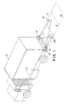
- FIG. 1 is a perspective view of a vehicle 10 and its detection area D located to the rear of the vehicle.
- Two of the three principal components of obstacle detection system 12 are shown in FIG. 1, both sensor clusters 14 and 16, and one exterior visual indicator 18, the second exterior visual indicator 20 is located on the other side of the vehicle and therefore is not pictured in FIG. 1.
- ultrasonic sensor clusters 14 and 16 are shown schematically as triangular or quarter circle shapes. The actual shape of a sensor cluster is shown in FIGS. 5-7 as described below. All of the components of detection system 12 are pictured schematically in FIG. 2, including exterior visual indicator 20 and audio-visual panel 22.
- Vehicle 10 has side view mirrors 24 and 26 mounted on the sides of the cab, and exterior visual indicators 18 and 20 are attached to the vehicle in locations which are in the lines of sight of mirrors 24 and 26 respectively, FIG. 3. Exemplary lines of sight are labeled LS in FIGS. 1, 4 and 8. Due to the location of visual indicators 18 and 20, a driver is not distracted in using the detection system since attention will already be given to mirrors 24 and 26 when backing-up.
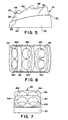
- FIGS. 5-7 are detailed top, front and side views respectively of sensor cluster 14.
- Sensor cluster 14 comprises a specially designed housing 30 having a vehicle attachment side 32 with an attachment edge 34 proximate the vehicle and a curved distal edge 36. Housing 30 also has a transceiving side 38 with a curved proximate edge 40 which defines the connection point with attachment side 32 and coincides with distal edge 36, and a stepped distal side 42.
- Sensor cluster 14 is configured to be mounted on the rear of vehicle 10 on the driver's seat side, and transceiving side 38 of housing 30 has an angled shape having stepped portions containing pairs of transmitters and receivers.
- Housing 30 has a roughly triangular shape with the narrow portion toward the center of the vehicle and the wider portion toward the outer edge of the vehicle.
- the curve of distal edge 36 of vehicle attachment side 32 extends from a narrower portion toward the center of the vehicle to a wider portion toward the outer edge.
- Attached to the distal edge of attachment side 32 is transceiving side 38 comprising three angled, stepped portions or surfaces, from the inside out, 44, 46 and 48.
- Each stepped portion includes an ultrasonic transmitter designated by a suffix "t" to the reference numeral, and an ultrasonic receiver designated by a suffix "r” to the reference numeral.
- transmitters 44t, 46t and 48t are positioned above corresponding receivers 44r, 46r and 48r, and are referred to as transceiver pairs.
- transceiver pairs Although the preferred embodiment employs transmitters and receivers, single unit transceivers which incorporate both functions may also be used. Any arrangement of transceiver pairs or single unit transceivers is contemplated to be within the scope of the invention.
- the angular relationships between stepped portions 44, 46 and 48 determine the amount of coverage of each transceiver pair. Stepped portions 44, 46 and 48 each cover areas having an approximate span of 30°.
- the angle labeled ⁇ illustrates the coverage area provided by the transceiver pairs of outer stepped portion 48 of sensor cluster 14. Similarly, angle ⁇ illustrates the coverage area provided by the transceiver pair in middle stepped portion 46, and angle ⁇ illustrates the coverage area provided by the transceiver pair in inner stepped portion 44.
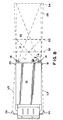
- the detection area D refers to the entire swath of coverage provided by sensor clusters 14 and 16 which is preferably equal to the width of the vehicle plus approximately 20cm to each side of area D. This narrow alley provides an added field of detection at the edges of the area without confusing the driver between visible and non-visible obstacles. This additional lateral coverage is shown in FIG. 8 as alley 28.
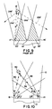
- sensor cluster 16 provides corresponding spans of coverage from its stepped portions, and the angles are labeled in FIG. 10.
- each sensor cluster covers approximately 90° which are divided into segments of approximately 30° each.
- the angled, stepped configuration of sensor clusters 14 and 16 provide coverage to the entire detection area D behind vehicle 10 with no gaps or "dead" spots.
- an obstacle 50 is located within the ⁇ segment of sensor cluster 16 and the ⁇ segment of sensor cluster 14. The lines of transmission and reception will be described herein with respect to the operation of the detection system.
- the base components of detection system 12 are shown in FIG. 11 and broadly comprise a microcomputer linked to a power source 1, a user interface 2 and transmitters 3 and receivers 4, or transceivers, which transmit the output signals and receive the input signals.
- the microcomputer functions can be performed using conventional circuit components, for example, a clock 5, a counter 6, registers 7, switching control logic 8 and comparators 9. Power is preferably supplied in parallel to the reverse lights of the vehicle so that the detection system is powered when the vehicle ignition switch is turned on and the vehicle is placed in reverse gear.
- the transmitters and receivers as discussed above, are integrated into the sensor clusters.
- the sensor clusters include transmitter arrays, such as 44t, 46t and 48t, for transmitting ultrasonic signals toward a target behind vehicle 10, and receiver arrays, such as 44r, 46r and 48r, for receiving return signals which are deflected from the target. As pictured, the sensor clusters are located at the two outer edges of the rear of the vehicle. Reception of the return signals occur in both monostatic and bistatic modes thereby enabling the logic circuit or computer to detect and calculate the distance of the closest targets within the coverage area.
- detection area D is also divided into proximity zones I, II and III.
- Proximity zone I is the zone closest to the back of the vehicle and extends to a predetermined distance indicated by broken line 52.
- Proximity zone II is further away from the vehicle and is bounded by line 52 and another broken line 53.
- Proximity zone III is behind zone II and is bounded by broken line 53 and another broken line 54.
- the distance from the back of the vehicle to line 52 is the minimum distance which will be allowed, and therefore proximity zone I is referred to as the imminent crash zone.
- the detection system will warn the driver to stop if any obstacle is detected in zone I.
- Proximity zone II is referred to as a warning zone, and the detection system will indicate that the driver is to proceed rearward with extreme caution if any obstacle is detected in zone II.
- Proximity zone III is referred to as a pre-warning zone, and the detection system will indicate that the driver is to proceed with caution if an obstacle is detected in zone III. If an obstacle is detected in the area beyond zone III, that is beyond line 54, the detection system will indicate an "all clear".
- the distances of lines 52, 53 and 54 from the rear of the vehicle are predetermined to be the boundaries of the zones. Those distances correspond to predetermined first, second and third thresholds which are stored within the computer memory. Broadly, the operation of the computer involves comparing a detected distance with the thresholds and activating the appropriate warning signal.
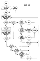
- FIG. 12 there are shown the principal program steps of the computer.
- the computer preferably performs a self-test and undergoes diagnostic testing. Any failure in the diagnostic routine will be indicated and further operation stopped. If the self-test is passed, the computer will proceed to perform a detecting algorithm using input from the sensor clusters.
- the transmitters and receivers of the sensor clusters operate in both monostatic and bistatic modes. To better understand these modes, reference is made to FIG. 10 in which line 56 indicates an ultrasound signal transmitted from sensor cluster 14 toward obstacle 50.
- the transmitted signal is deflected in two ways and will be received in two ways: monostatically referring to return signal 58 which is received by the same transceiver pair that sent it, and bistatically referring to return signal 60 which is received by a different transceiver pair located in sensor cluster 16.
- lines 56 and 58 should coincide but are shown separated for clarity of illustration. Because of the configuration of the sensor clusters and their shapes, the entire detection area behind the vehicle is covered as seen in FIG. 10. In contrast, in the prior art system shown in FIG. 9, the angularly oriented obstacle 18' is only within the area covered by one sensor 12', and the deflected signals 24b' and 26b' stray away from any receivers so that obstacle 18' should not be detected.
- Exterior visual indicators 18 and 20 are preferably provided with different colored lights directed toward the side view mirrors. Similar to a traffic signal, top light 62 is red, middle light 64 is yellow, and bottom light 66 is green. The three lights form part of the user interface which communicates with the driver in response to obstacles detected behind the vehicle. As described above, an audible alarm may sound from the audio-visual panel 22, and FIG. 13 illustrates the audible signal outputs corresponding to the various thresholds of warning of the visual indicators.
- the sensor clusters can detect a plurality of obstacles and the computer calculates the distance to the closest one.
- the computer calculates the distance by measuring the time lapse between the transmission of a signal and the receipt of its return signal, angle and the distance between the clusters.
- Stored within the computer memory is a first threshold corresponding to the minimum permitted distance between the back of the vehicle and the closest obstacle, that is the distance to line 52 in FIG. 8 covering zone I.
- a second threshold in memory is larger than the first threshold and corresponds to a distance from the back of the vehicle which is sufficiently close to warrant extreme caution, that is the distance to line 53 covering zone II.
- a third threshold in memory is larger than the second and corresponds to a distance which warrants caution in backing-up, that is the distance to line 54 covering zone III.
- a short range target search in both bistatic and monostatic modes is performed, and if a target obstacle is detected, the computer calculates the distance to the obstacle using a conventional computing technique.
- the computing technique uses a conventional clock/timer circuit to measure the difference between the time a signal or pulse is transmitted and a return signal or pulse is received by the sensor clusters.
- the detection system uses a multi-target screening technique which ensures that the first returned signal or pulse is used in the computing technique regardless of whether that returned signal or pulse was received monostatically or bistatically.
- the calculated distance is compared with the first threshold and if it is less than the first threshold, a red light is illuminated on exterior visual indicators 18 and 20, by lighting top lights 62 indicating that an obstacle has been detected in collision zone I and signalling the driver to stop. In conjunction with the red lights, a specific audible signal corresponding to this warning may sound inside the vehicle from audio-visual panel 22.
- FIG. 13 illustrates the audible signal output. If the calculated distance is not less than the first threshold, it is compared with the second threshold. If the calculated distance is less than the second threshold, yellow lights are flashed by intermittently lighting middle lights 64 indicating that an obstacle has been detected in warning zone II and signalling the motorist to proceed with extreme caution.
- the calculated distance is greater than the second threshold, it is compared with the third threshold, and if it is less than the third threshold, yellow lights are illuminated by lighting middle lights 64 indicating that an obstacle has been detected in pre-warning zone III and signalling the driver to proceed with caution. If the calculated distance is greater than the third threshold, then an "all clear" is indicated either by illuminating none of the lights or lighting green bottom lights 66 signalling the driver that no obstacles have been detected in detection zone D and to proceed with normal care and caution. With each of the above levels of warning, a suitable corresponding audible signal may sound from audio-visual panel 22 within the vehicle. Panel 22 may include a series of lights which correspond to the lights on exterior visual indicators 18 and 20, although these may be secondary to the exterior lights in function.
- the target detection, distance calculation and visual and/or auditory indication steps are repeated continuously in a programming loop as shown figuratively in FIG. 12 providing continual monitoring of the detection area when the detection system is engaged.
- a sub-part of the detection algorithm is a "disappearing target algorithm" which will indicate to the driver that a target obstacle has been detected in successive zones and then has “disappeared” in a subsequent iteration and signal the driver by illuminating both the yellow and red lights.
- a broken line delineates the disappearing target sub-algorithm. After a target has been detected and is not detected again in the immediately following iteration, a series of decision operations are performed. If any of the lights were lit or the yellow light flashed in the immediately preceding iteration of the detection algorithm, then both the yellow and red lights are illuminated to warn the driver of an obstacle that has "disappeared.” If all of the decision operations are answered in the negative, then an all clear signal is given by illuminating the green light or no light at all.
- Obstacle 68 is block shaped and is located in collision zone I
- obstacle 70 is cylindrical and is located in warning zone II.
- the transmitters of sensor clusters 14 and 16 transmit ultrasound signals toward detection area D and the signals are deflected off of obstacles 68 and 70 and received by the receivers of the sensor clusters. Some return signals will be received by a receiver on the same cluster that sent the signal and other return signals will be received by a receiver on the other cluster, thereby providing monostatic and bistatic operation.
- the computer which is located in one of the sensor clusters will calculate the distance to the closest obstacle because the return signal from the closest target will be determined by the multi-target screening technique.
- obstacle 68 is the closest and the distance to it will be calculated.
- the computer will determine that obstacle 68 is located in collision zone I and will sent an output signal to the user interface to illuminate red lights 62 and to cause an audible alarm to sound from audio-visual panel 22 within the vehicle warning the motorist to stop. If obstacle 68 were not present, of course the computer would calculate the distance to obstacle 70 which is located in the warning zone II and send an output signal to the user interface to flash yellow lights 64 warning the motorist to proceed with extreme caution.
- FIG. 12 and FIG. 13 show only the principal steps of the computer program and that many other embodiments are possible without in any way departing from the spirit of the invention. For example, there are an infinite number of thresholds possible to provide additional levels of warning to the driver.
- the present detection system provides the best available coverage of the area behind the vehicle.
- the configuration of the sensor clusters on both sides of the rear of the vehicle enables the computer through its seek-and-store detection algorithm to transmit signals from every transmitter in each array and consequently receive return signals deflected from an obstacle into every one of the available receivers, thereby being able to recognize even very small objects with odd shapes and textures.
- the obstacle detection system of the present invention provides multiple levels of cautionary warnings by continually monitoring the detection area.
- the angled, stepped configuration of the sensor clusters provide the expanded coverage of detection area D.
- Exterior visual indicators 18 and 20 are attached to the sides of the vehicle so that their lights are viewed in the side view mirrors visible to the motorist while maneuvering in reverse.
- the preferred orientation of indicators 18 and 20 are within 15° vertically and within 15° horizontally of the driver's line of sight of the side view mirrors.
- Additional visual display and audio tone warning is located on audio-visual panel 22 in the cab sounding alarms.
- Panel 22 may also include a series of lights which communicate visually as well.
- transmitters and receivers or single unit transceivers are constituted by an ultrasonic detectors, it will clearly be understood that sonic, optical infrared, RF, and radar detectors are equally suitable.
- the detection algorithm described herein pertains to the preferred embodiment of the invention. It will be understood that alternative algorithms may be formulated and used with the detection system components of the present invention.
Landscapes
- Engineering & Computer Science (AREA)
- Remote Sensing (AREA)
- Radar, Positioning & Navigation (AREA)
- Physics & Mathematics (AREA)
- Computer Networks & Wireless Communication (AREA)
- Acoustics & Sound (AREA)
- Mechanical Engineering (AREA)
- Human Computer Interaction (AREA)
- Transportation (AREA)
- General Physics & Mathematics (AREA)
- Measurement Of Velocity Or Position Using Acoustic Or Ultrasonic Waves (AREA)
- Radar Systems Or Details Thereof (AREA)
- Traffic Control Systems (AREA)
- Geophysics And Detection Of Objects (AREA)
- Control Of Position, Course, Altitude, Or Attitude Of Moving Bodies (AREA)
- Control Of Driving Devices And Active Controlling Of Vehicle (AREA)
- Optical Radar Systems And Details Thereof (AREA)
Abstract
Description
Claims (20)
- An obstacle detection system (12) for a vehicle (10) moving in reverse for warning a driver of obstacles in a detection area (D) to the rear of the vehicle and adapted to be operatively coupled to a computer and an output indicator, said detection system comprising:sensing means comprising an array of signal receiving means (44r, 46r, 48r) for receiving signals deflected from a target object (50, 68, 70) located in the detection area;detection means coupled to said receiving means (44r, 46r, 48r) for detecting the presence of a target object in the detection area iteratively, said detection means comprising:multi-target screening means for screening return signals and determining one which corresponds to a closest target object;calculating means for calculating the distance from the rear of the vehicle to the closest target object;memory means for storing a first threshold value corresponding to a minimum distance allowed between an obstacle in the detection area and the rear of the vehicle;first comparator means for comparing the calculated distance to the first threshold distance and generating a first output signal if the calculated distance is less than the first threshold distance; andan indicator coupled to said detection means and responsive to the first output signal for indicating to the driver to activate the brakes and to stop the vehicle or signalling directly to the brake system to activate the brakes, characterised in that:said obstacle detection system further comprises:a housing (30) comprising a plurality of stepped portions (44, 46, 48) oriented angularly with respect to one another and a vehicle mount portion (32) for mounting said housing to the rear of a vehicle (10); and in thatsaid sensing means further comprises an angled, stepped sensor cluster (14, 16) contained in said housing for attachment to the rear of the vehicle (10), said sensor cluster comprising an array of signal transmitting means (44t, 46t, 48t) for transmitting signals from the rear of the vehicle and said array of signal receiving means (44r, 46r, 48r), said transmitting means and said receiving means being disposed in said stepped portions of said housing so as to provide an angular area of signal transmitting and receiving coverage.
- The obstacle detection system of claim 1, wherein said indication means comprises an exterior visual indicator (18,20) attached to the vehicle so as to be visible to the driver through viewing a side view mirror of the vehicle.
- The obstacle detection system of claim 2, wherein said exterior visual indicator (18,20) includes a red light and a yellow light adapted to be illuminated in response to output signals from said detection means.
- The obstacle detection system of claim 3, wherein in response to the first output signal said red light of said exterior visual indicator is illuminated signalling the driver to stop the vehicle.
- The obstacle detection system of claim 3, wherein said memory means further comprises a second threshold value corresponding to a warning distance between an obstacle in the detection area and the rear of the vehicle, and wherein said detection means further comprises second comparator means for comparing the calculated distance to the second threshold distance and generating a second output signal if the obstacle is in a warning zone such that the calculated distance is less than the second threshold distance but greater than the first threshold distance, and said indicating means being further responsive to the second output signal for signalling the driver of an obstacle in the warning zone.
- The obstacle detection system of claim 5, wherein in response to the second output signal said yellow light of said exterior visual indicator is intermittently illuminated signalling the driver to proceed in reverse with extreme caution.
- The obstacle detection system of claim 3, wherein said memory means further comprises a third threshold value corresponding to a pre-warning distance between an obstacle (50) in the detection area and the rear of the vehicle, and wherein said detection means further comprises third comparator means for comparing the calculated distance to the third threshold distance and generating a third output signal if the obstacle is in a pre-warning zone (III) such that the calculated distance is less than the third threshold distance but grater than the second threshold distance, and said indicating means being further responsive to the third output signal for signalling the driver of an obstacle in the pre-warning zone.
- The obstacle detection system of claim 7, wherein in response to the third output signal said yellow light of said exterior visual indicator (18,20) is illuminated signalling the driver to proceed in reverse with caution.
- The obstacle detection system of claim 7, wherein said detection means is adapted to generate a fourth output signal if the calculated distance is greater than the third threshold, and said indicating means being further responsive to the fourth output signal for signalling the driver of no obstacles detected in the detection area.
- The obstacle detection system of claim 9, wherein said indicating means further comprises a green light on said exterior visual indicator (18,20) and in response to the fourth output signal said green light is illuminated signalling the driver to proceed with normal care and caution.
- The obstacle detection system of claim 1, wherein said indication means comprises an audible alarm alerting the driver to stop the vehicle.
- The obstacle detection system of claim 1, comprising a pair of sensor (44t, 46t, 48t, 44r, 46r, 48r) clusters wherein one said sensor cluster is mounted to the driver's side of the rear of the vehicle and another said sensor cluster is mounted to the passenger's side of the rear of the vehicle, each said sensor cluster providing an angular coverage area, said sensor clusters angled toward each other such that their angular coverage areas intersect.
- The obstacle detection system of claim 12, wherein the angular coverage area of each said sensor cluster is approximately 90°.
- The obstacle detection system of claim 13, wherein the coverage area of each said sensor cluster comprises three angular coverage segments of approximately 30° each.
- The obstacle detection system of claim 14, wherein said angular area of coverage comprises a plurality of angular coverage segments, said transmitters and said receivers in each said stepped portion of said housing providing one angular coverage segment.
- The obstacle detection system of claim 15, wherein said angular area of coverage is approximately 90° such that the sum of said angular coverage segments equals approximately 90°.
- The obstacle detection system of claim 16, wherein said angular coverage segments are approximately 30° each such that three segments comprise said angular area of coverage.
- The obstacle detection system of claim 1, wherein said indication means comprises an audible alarm which sounds only if a target object is present in the detection area in response to the first output signal alerting the driver to stop the vehicle.
- The obstacle detection system of claim 5, wherein said indication means comprises an audible alarm which sounds only if a target object is present in the detection area in response to the second output signal signalling the driver to proceed in reverse with extreme caution.
- The obstacle detection system of claim 7, wherein said indication means comprises an audible alarm which sounds only if a target object is present in the detection area in response to the third output signal signalling the driver to proceed in reverse with caution.
Applications Claiming Priority (3)
| Application Number | Priority Date | Filing Date | Title |
|---|---|---|---|
| US497429 | 1995-06-30 | ||
| US08/497,429 US5574426A (en) | 1995-06-30 | 1995-06-30 | Obstacle detection system for vehicles moving in reverse |
| PCT/IB1996/000728 WO1997002155A1 (en) | 1995-06-30 | 1996-06-27 | Obstacle detection system for vehicles moving in reverse |
Publications (3)
| Publication Number | Publication Date |
|---|---|
| EP0830266A1 EP0830266A1 (en) | 1998-03-25 |
| EP0830266A4 EP0830266A4 (en) | 1998-12-02 |
| EP0830266B1 true EP0830266B1 (en) | 2002-03-06 |
Family
ID=23976834
Family Applications (1)
| Application Number | Title | Priority Date | Filing Date |
|---|---|---|---|
| EP96922185A Expired - Lifetime EP0830266B1 (en) | 1995-06-30 | 1996-06-27 | Obstacle detection system for vehicles moving in reverse |
Country Status (11)
| Country | Link |
|---|---|
| US (1) | US5574426A (en) |
| EP (1) | EP0830266B1 (en) |
| JP (1) | JPH11509153A (en) |
| AT (1) | ATE214010T1 (en) |
| AU (1) | AU703104B2 (en) |
| CA (1) | CA2225735A1 (en) |
| DE (1) | DE69619670T2 (en) |
| DK (1) | DK0830266T3 (en) |
| ES (1) | ES2171689T3 (en) |
| PT (1) | PT830266E (en) |
| WO (1) | WO1997002155A1 (en) |
Families Citing this family (150)
| Publication number | Priority date | Publication date | Assignee | Title |
|---|---|---|---|---|
| US6856873B2 (en) * | 1995-06-07 | 2005-02-15 | Automotive Technologies International, Inc. | Vehicular monitoring systems using image processing |
| US5910854A (en) | 1993-02-26 | 1999-06-08 | Donnelly Corporation | Electrochromic polymeric solid films, manufacturing electrochromic devices using such solid films, and processes for making such solid films and devices |
| US5668663A (en) | 1994-05-05 | 1997-09-16 | Donnelly Corporation | Electrochromic mirrors and devices |
| DE19501642B4 (en) * | 1995-01-20 | 2008-01-17 | Robert Bosch Gmbh | Method for contactless distance measurement |
| US6891563B2 (en) * | 1996-05-22 | 2005-05-10 | Donnelly Corporation | Vehicular vision system |
| DE19615240A1 (en) * | 1996-04-18 | 1997-10-23 | Daimler Benz Ag | Arrangement for optical detection of the course of the road |
| US5754123A (en) * | 1996-05-06 | 1998-05-19 | Ford Motor Company | Hybrid ultrasonic and radar based backup aid |
| KR980008783A (en) * | 1996-07-12 | 1998-04-30 | 김영귀 | Cornering assist system and its operation method |
| JPH1067252A (en) * | 1996-08-29 | 1998-03-10 | Aisin Seiki Co Ltd | Vehicle running state detection device |
| US6124886A (en) | 1997-08-25 | 2000-09-26 | Donnelly Corporation | Modular rearview mirror assembly |
| US8294975B2 (en) | 1997-08-25 | 2012-10-23 | Donnelly Corporation | Automotive rearview mirror assembly |
| US6172613B1 (en) | 1998-02-18 | 2001-01-09 | Donnelly Corporation | Rearview mirror assembly incorporating vehicle information display |
| US6326613B1 (en) | 1998-01-07 | 2001-12-04 | Donnelly Corporation | Vehicle interior mirror assembly adapted for containing a rain sensor |
| US5945907A (en) * | 1997-10-27 | 1999-08-31 | Michael Yaron | Apparatus and methods for parking a vehicle using position detection sensor |
| US6173215B1 (en) * | 1997-12-19 | 2001-01-09 | Caterpillar Inc. | Method for determining a desired response to detection of an obstacle |
| US6124647A (en) * | 1998-12-16 | 2000-09-26 | Donnelly Corporation | Information display in a rearview mirror |
| US6690268B2 (en) | 2000-03-02 | 2004-02-10 | Donnelly Corporation | Video mirror systems incorporating an accessory module |
| US6445287B1 (en) | 2000-02-28 | 2002-09-03 | Donnelly Corporation | Tire inflation assistance monitoring system |
| US8288711B2 (en) | 1998-01-07 | 2012-10-16 | Donnelly Corporation | Interior rearview mirror system with forwardly-viewing camera and a control |
| US6044632A (en) * | 1998-02-05 | 2000-04-04 | Eaton Corporation, Cutler-Hammer Products | Backup proximity sensor for a vehicle |
| US6380883B1 (en) | 1998-02-23 | 2002-04-30 | Amerigon | High performance vehicle radar system |
| US6069581A (en) | 1998-02-20 | 2000-05-30 | Amerigon | High performance vehicle radar system |
| US6329925B1 (en) | 1999-11-24 | 2001-12-11 | Donnelly Corporation | Rearview mirror assembly with added feature modular display |
| US6693517B2 (en) | 2000-04-21 | 2004-02-17 | Donnelly Corporation | Vehicle mirror assembly communicating wirelessly with vehicle accessories and occupants |
| US6477464B2 (en) | 2000-03-09 | 2002-11-05 | Donnelly Corporation | Complete mirror-based global-positioning system (GPS) navigation solution |
| US6693524B1 (en) * | 1998-06-02 | 2004-02-17 | George R. Payne | Vehicle backup monitoring and alarm system |
| DE19831262C2 (en) * | 1998-07-11 | 2002-09-19 | Wabco Gmbh & Co Ohg | Device to support the driver of a commercial vehicle when reversing |
| DE19839942C2 (en) * | 1998-09-02 | 2001-07-12 | Mannesmann Vdo Ag | Parking aid for a motor vehicle |
| US6211778B1 (en) * | 1998-09-14 | 2001-04-03 | Michael J. Reeves | Vehicle safety sensor |
| US6606027B1 (en) | 1998-09-14 | 2003-08-12 | Michael J. Reeves | Vehicle safety sensor system |
| US20040046647A1 (en) * | 2000-11-21 | 2004-03-11 | Reeves Michael J. | Vehicle safety sensor system |
| DE19843564A1 (en) * | 1998-09-23 | 2000-03-30 | Bosch Gmbh Robert | Warning device for a motor vehicle |
| US6021373A (en) * | 1998-12-21 | 2000-02-01 | Eaton Corporation | Back-up proximity sensor for a vehicle |
| DE19901953B4 (en) * | 1999-01-20 | 2014-02-06 | Robert Bosch Gmbh | Device and method for stabilizing a vehicle combination |
| US6225918B1 (en) | 1999-02-19 | 2001-05-01 | Bing Kam | Automatic warning signal system for vehicles |
| US6734807B2 (en) * | 1999-04-01 | 2004-05-11 | Lear Automotive Dearborn, Inc. | Polarametric blind spot detector with steerable beam |
| US6114950A (en) * | 1999-05-03 | 2000-09-05 | Specam Technologies, Inc. | Obstacle proximity warning device for vehicles |
| US6204754B1 (en) * | 1999-06-17 | 2001-03-20 | International Business Machines Corporation | Proximity indicating system |
| US6894608B1 (en) | 1999-07-22 | 2005-05-17 | Altra Technologies Incorporated | System and method for warning of potential collisions |
| JP3714116B2 (en) * | 1999-08-09 | 2005-11-09 | トヨタ自動車株式会社 | Steering stability control device |
| AU782231B2 (en) * | 1999-11-25 | 2005-07-14 | Global 7 Group Pty Ltd | Mobile plant proximity detection and warning system |
| US6133826A (en) * | 1999-12-07 | 2000-10-17 | Motorola, Inc. | Method and apparatus for detecting objects |
| US6642839B1 (en) * | 2000-02-16 | 2003-11-04 | Altra Technologies Incorporated | System and method of providing scalable sensor systems based on stand alone sensor modules |
| US7167796B2 (en) | 2000-03-09 | 2007-01-23 | Donnelly Corporation | Vehicle navigation system for use with a telematics system |
| US7370983B2 (en) | 2000-03-02 | 2008-05-13 | Donnelly Corporation | Interior mirror assembly with display |
| US7046127B2 (en) * | 2000-05-09 | 2006-05-16 | Terence Boddy | Electronic reversing aid with wireless transmitter and receiver |
| US6634139B1 (en) * | 2000-07-25 | 2003-10-21 | Donald Metz | Dock light warning system |
| US6431001B1 (en) * | 2000-08-31 | 2002-08-13 | Denso Corporation | Obstacle detecting system having snow detecting function |
| JP2002131428A (en) * | 2000-10-25 | 2002-05-09 | Mitsubishi Electric Corp | Ultrasonic obstacle detection device |
| US7148815B2 (en) * | 2000-12-22 | 2006-12-12 | Byron Scott Derringer | Apparatus and method for detecting objects located on an airport runway |
| US20020130770A1 (en) * | 2000-12-29 | 2002-09-19 | Dennis Keyworth | Object sensor with integrally molded housing and method for making same |
| EP1363810B1 (en) | 2001-01-23 | 2007-05-30 | Donnelly Corporation | Improved vehicular lighting system |
| US7255451B2 (en) | 2002-09-20 | 2007-08-14 | Donnelly Corporation | Electro-optic mirror cell |
| US7581859B2 (en) | 2005-09-14 | 2009-09-01 | Donnelly Corp. | Display device for exterior rearview mirror |
| US6734799B2 (en) * | 2001-03-01 | 2004-05-11 | Trw Inc. | Apparatus and method for responding to the health and fitness of a driver of a vehicle |
| US6720868B2 (en) * | 2001-05-31 | 2004-04-13 | Omega Patents, L.L.C. | Back-up warning system in a license plate holder and related method |
| US6879248B2 (en) * | 2001-05-31 | 2005-04-12 | Omega Patents, L.L.C. | Back-up warning system for a vehicle and related method |
| US6542085B1 (en) * | 2001-10-04 | 2003-04-01 | Whetron Industrial Co., Ltd. | Distance measuring and monitoring device equipped automobile reverse radar |
| JP4108314B2 (en) * | 2001-10-31 | 2008-06-25 | トヨタ自動車株式会社 | Vehicle periphery monitoring device |
| US7265663B2 (en) | 2001-11-28 | 2007-09-04 | Trivinci Systems, Llc | Multimedia racing experience system |
| US20030105558A1 (en) * | 2001-11-28 | 2003-06-05 | Steele Robert C. | Multimedia racing experience system and corresponding experience based displays |
| US6933837B2 (en) | 2002-01-25 | 2005-08-23 | Altra Technologies Incorporated | Trailer based collision warning system and method |
| US6731204B2 (en) * | 2002-02-19 | 2004-05-04 | Continental Teves, Inc. | Object detection system providing driver information through sound |
| US7123168B2 (en) * | 2002-04-25 | 2006-10-17 | Donnelly Corporation | Driving separation distance indicator |
| US6918674B2 (en) | 2002-05-03 | 2005-07-19 | Donnelly Corporation | Vehicle rearview mirror system |
| WO2003105099A1 (en) | 2002-06-06 | 2003-12-18 | Donnelly Corporation | Interior rearview mirror system with compass |
| EP1532462A4 (en) * | 2002-06-06 | 2005-12-21 | Roadeye Flr General Partnershi | Forward-looking radar system |
| US7329013B2 (en) | 2002-06-06 | 2008-02-12 | Donnelly Corporation | Interior rearview mirror system with compass |
| US6864783B2 (en) * | 2002-07-25 | 2005-03-08 | Ford Global Technologies, Llc | Potential collision detection and reversing aid system |
| US6870473B2 (en) * | 2002-08-01 | 2005-03-22 | Wabash National, L.P. | Corner-post mounted, status light display for a semi-trailer |
| DE20213978U1 (en) * | 2002-09-06 | 2002-12-05 | Voit, Stefan, Dipl.-Wirtsch.-Ing., 66386 St Ingbert | Electronic distance warning system |
| US7076366B2 (en) * | 2002-09-06 | 2006-07-11 | Steven Simon | Object collision avoidance system for a vehicle |
| US7310177B2 (en) | 2002-09-20 | 2007-12-18 | Donnelly Corporation | Electro-optic reflective element assembly |
| AU2003278863A1 (en) | 2002-09-20 | 2004-04-08 | Donnelly Corporation | Mirror reflective element assembly |
| US6982634B2 (en) * | 2002-11-07 | 2006-01-03 | Shih-Hsiung Li | Method and apparatus for reducing blind spots in obstacle detection |
| US6927677B2 (en) * | 2003-03-14 | 2005-08-09 | Darryll Anderson | Blind spot detector system |
| DE10313002B4 (en) * | 2003-03-24 | 2006-03-23 | Daimlerchrysler Ag | Vehicle environment detection unit |
| US7289037B2 (en) | 2003-05-19 | 2007-10-30 | Donnelly Corporation | Mirror assembly for vehicle |
| JP2005008020A (en) * | 2003-06-18 | 2005-01-13 | Denso Corp | Vehicle travel information notification device |
| ITMO20030024U1 (en) * | 2003-07-11 | 2005-01-12 | Meta System Spa | PLATE HOLDER FOR VEHICLES WITH SUPPORTS FOR DETECTION DEVICES, OF THE SENSOR TYPE, MICROTELECAMER OR SIMILAR TRANSDUCERS |
| KR20050020601A (en) * | 2003-08-19 | 2005-03-04 | 주식회사 현대오토넷 | Back warning system for vehicles |
| US7446924B2 (en) | 2003-10-02 | 2008-11-04 | Donnelly Corporation | Mirror reflective element assembly including electronic component |
| US7308341B2 (en) | 2003-10-14 | 2007-12-11 | Donnelly Corporation | Vehicle communication system |
| US7341264B2 (en) * | 2003-10-30 | 2008-03-11 | Mark Swannie | Trailer hitch mounted reverse sensing system |
| US7239958B2 (en) * | 2003-12-18 | 2007-07-03 | General Motors Corporation | Apparatus and method for discerning a driver's intent and for aiding the driver |
| DE202004007063U1 (en) * | 2004-05-04 | 2005-09-15 | Liebherr Werk Nenzing Gmbh Nen | Reach Stacker |
| US20050253693A1 (en) * | 2004-05-11 | 2005-11-17 | Mark Rennick | Object detection system, apparatus, and method |
| US20050257975A1 (en) * | 2004-05-19 | 2005-11-24 | Cavin John C | Expressway safety mirror |
| US7106183B2 (en) * | 2004-08-26 | 2006-09-12 | Nesa International Incorporated | Rearview camera and sensor system for vehicles |
| JP2006098359A (en) * | 2004-09-30 | 2006-04-13 | Denso Corp | Obstacle detection device |
| KR101115221B1 (en) * | 2005-01-07 | 2012-02-14 | 주식회사 현대오토넷 | Vehicle proximity warning system and method |
| JP4179285B2 (en) * | 2005-01-12 | 2008-11-12 | トヨタ自動車株式会社 | Parking assistance device |
| US20060187010A1 (en) * | 2005-02-18 | 2006-08-24 | Herbert Berman | Vehicle motion warning device |
| GB2424984A (en) * | 2005-04-06 | 2006-10-11 | Lee Bosanko | Reversing system for a vehicle housed in an under run bar |
| US20060001545A1 (en) * | 2005-05-04 | 2006-01-05 | Mr. Brian Wolf | Non-Intrusive Fall Protection Device, System and Method |
| ATE517368T1 (en) | 2005-05-16 | 2011-08-15 | Donnelly Corp | VEHICLE MIRROR ARRANGEMENT WITH CHARACTER ON THE REFLECTIVE PART |
| US7339462B1 (en) | 2005-09-06 | 2008-03-04 | Chris Diorio | Reverse gear volume reducer |
| TWM284569U (en) * | 2005-10-12 | 2006-01-01 | Cing-Liang Lyu | Wide-angle rearview mirror assembly for rearview and car-backing monitoring |
| US20070088488A1 (en) * | 2005-10-14 | 2007-04-19 | Reeves Michael J | Vehicle safety system |
| US7496439B2 (en) * | 2005-10-17 | 2009-02-24 | Lang Mekra North America, Llc | Multifunction exterior display for a vehicle mirror |
| EP1949666B1 (en) | 2005-11-01 | 2013-07-17 | Magna Mirrors of America, Inc. | Interior rearview mirror with display |
| US7362216B2 (en) * | 2005-11-17 | 2008-04-22 | Shih-Hsiung Li | Reversing sensor without a control box |
| US20070120707A1 (en) * | 2005-11-29 | 2007-05-31 | Rv Insite, Inc. | Method for positioning recreational vehicles and portable position sensor and alert system for recreational vehicles and other vehicles |
| KR100696392B1 (en) * | 2005-12-07 | 2007-03-19 | 주식회사단해 | Vehicle outside monitoring system and method |
| US8194132B2 (en) | 2006-01-20 | 2012-06-05 | Old World Industries, Llc | System for monitoring an area adjacent a vehicle |
| JP4875541B2 (en) * | 2006-08-28 | 2012-02-15 | 株式会社日本自動車部品総合研究所 | Direction detection method, object detection device, program |
| FR2906372B1 (en) * | 2006-09-21 | 2010-06-18 | Derisys | DEVICE FOR AIDING THE DRIVING OF A MOTOR VEHICLE |
| DE102006051961A1 (en) * | 2006-11-03 | 2008-05-15 | Robert Bosch Gmbh | Device for adjusting the distance of a motor vehicle |
| US7719410B2 (en) * | 2007-01-08 | 2010-05-18 | Gm Global Technology Operations, Inc. | Threat assessment state processing for collision warning, mitigation and/or avoidance in ground-based vehicles |
| US7830243B2 (en) * | 2007-02-02 | 2010-11-09 | Chrysler Group Llc | Dual mode vehicle blind spot system |
| US7957874B2 (en) * | 2007-03-19 | 2011-06-07 | GM Global Technology Operations LLC | Override of automatic braking in a collision mitigation and/or avoidance system |
| WO2009011250A1 (en) * | 2007-07-17 | 2009-01-22 | Honda Motor Co., Ltd. | Obstacle device for vehicle driving experience |
| US8190355B2 (en) * | 2007-10-10 | 2012-05-29 | International Business Machines Corporation | Driving assistance and monitoring |
| DE102007053400B4 (en) * | 2007-11-09 | 2017-11-16 | Continental Automotive Gmbh | Method and device for detecting the approach of a vehicle to an object |
| DE202008003306U1 (en) | 2008-03-08 | 2008-09-18 | Wabco Gmbh | Device for arranging environmental sensors in a vehicle |
| US8154418B2 (en) | 2008-03-31 | 2012-04-10 | Magna Mirrors Of America, Inc. | Interior rearview mirror system |
| US8508366B2 (en) * | 2008-05-12 | 2013-08-13 | Robert Bosch Gmbh | Scanning security detector |
| JP4880712B2 (en) * | 2009-02-27 | 2012-02-22 | 株式会社日本自動車部品総合研究所 | Obstacle detection device |
| DE102009046158A1 (en) * | 2009-10-29 | 2011-05-05 | Robert Bosch Gmbh | Method for detecting objects with low height |
| SE535786C2 (en) * | 2010-01-19 | 2012-12-18 | Volvo Technology Corp | Dead Angle Warning System |
| US8662898B2 (en) * | 2010-03-15 | 2014-03-04 | Joan Bellontine | Goal achievement game and method |
| DE102010030466B4 (en) | 2010-06-24 | 2021-05-20 | Robert Bosch Gmbh | Procedure for warning a driver of a collision |
| DE102010032909A1 (en) | 2010-07-30 | 2012-02-02 | Wabco Gmbh | Monitoring system for monitoring the environment, in particular the rear space of motor vehicles |
| DE102011084589A1 (en) * | 2011-10-17 | 2013-04-18 | Robert Bosch Gmbh | Device for assisting driver of motor vehicle during reversing vehicle or maneuvering in dark, has lighting device illuminating rear portion of vehicle based on steering angle, and ultrasonic sensor detecting living objects in rear portion |
| DE102012016255A1 (en) * | 2012-08-16 | 2014-02-20 | GM Global Technology Operations, LLC (n.d. Ges. d. Staates Delaware) | A method of warning a subsequent motor vehicle |
| DE102012020263B4 (en) * | 2012-10-12 | 2018-03-08 | Audi Ag | Pedestrian protection impactor for simulating a pedestrian impact on a vehicle |
| JP5798150B2 (en) * | 2013-05-30 | 2015-10-21 | 本田技研工業株式会社 | Object detection device |
| CN104280739A (en) * | 2013-07-10 | 2015-01-14 | 富泰华工业(深圳)有限公司 | Distance measurement system and method |
| DE102014200692A1 (en) * | 2014-01-16 | 2015-07-16 | Robert Bosch Gmbh | PROCESS, ANTENNA ARRANGEMENT, RADAR SYSTEM AND VEHICLE |
| US9423497B2 (en) * | 2014-02-17 | 2016-08-23 | Radar Obstacle Detection Ltd. | Obstacle map reconstruction system and method |
| US9342747B2 (en) * | 2014-04-14 | 2016-05-17 | Bendix Commercial Vehicle Systems Llc | Vehicle driver assistance apparatus for assisting a vehicle driver in maneuvering the vehicle relative to an object |
| TW201541423A (en) * | 2014-04-25 | 2015-11-01 | Autoequips Tech Co Ltd | Obstacle warning system |
| EP2962898B1 (en) | 2014-07-03 | 2021-11-10 | Volvo Car Corporation | A method and system for generating an alarm signal in a vehicle |
| JP6403055B2 (en) * | 2014-10-03 | 2018-10-10 | パナソニックIpマネジメント株式会社 | Object detection device |
| US9315175B1 (en) | 2014-10-08 | 2016-04-19 | Ford Global Technologies, Llc | Automatic braking override system |
| EP3209509B1 (en) | 2014-10-23 | 2019-09-04 | Carrier Corporation | Coupling assist system for a tractor trailer |
| US10486742B2 (en) * | 2016-08-01 | 2019-11-26 | Magna Electronics Inc. | Parking assist system using light projections |
| CN109690349B (en) * | 2016-09-15 | 2023-10-31 | 株式会社小糸制作所 | sensor system |
| US10391931B2 (en) * | 2017-06-12 | 2019-08-27 | GM Global Technology Operations LLC | System and method for providing enhanced passenger use of an autonomous vehicle |
| US10339392B2 (en) * | 2017-06-15 | 2019-07-02 | Blackberry Limited | Method and system for rear status detection |
| US10131323B1 (en) * | 2017-09-01 | 2018-11-20 | Gentex Corporation | Vehicle notification system for approaching object detection |
| US10906542B2 (en) * | 2018-06-26 | 2021-02-02 | Denso International America, Inc. | Vehicle detection system which classifies valid or invalid vehicles |
| US10882538B1 (en) * | 2019-07-31 | 2021-01-05 | Karma Automotive Llc | System and method for a combined visual and audible spatial warning system |
| US11151874B2 (en) * | 2020-01-23 | 2021-10-19 | Frogparking Limited | Vehicle flow monitoring system |
| US11535257B2 (en) * | 2020-05-22 | 2022-12-27 | Robert Bosch Gmbh | Lane localization system and method |
| EP4196838B1 (en) | 2020-08-12 | 2025-07-09 | ZF CV Systems Global GmbH | Sensor housing, housing-integrated sensor- and cleaning-device and vehicle |
| CN112423218B (en) * | 2020-09-29 | 2023-05-26 | 红点定位(北京)科技有限公司 | Social distance alarm method, device, computer equipment and storage medium |
| JP7789627B2 (en) * | 2022-06-21 | 2025-12-22 | 日野自動車株式会社 | Abnormality diagnosis device |
| WO2025227240A1 (en) * | 2024-05-03 | 2025-11-06 | Global Sensor Systems Inc. | Methods, systems and apparatus for improved automatic reverse object detection and braking of vocational vehicles |
| CN120503699B (en) * | 2025-07-22 | 2025-09-23 | 成都赛力斯科技有限公司 | Car lamp control method and device, computer equipment and storage medium |
Family Cites Families (12)
| Publication number | Priority date | Publication date | Assignee | Title |
|---|---|---|---|---|
| US4467313A (en) * | 1980-11-14 | 1984-08-21 | Nippon Soken, Inc. | Automotive rear safety checking apparatus |
| DE3244358C2 (en) * | 1982-12-01 | 1984-10-04 | Daimler-Benz Ag, 7000 Stuttgart | Device for detecting obstacles as a maneuvering aid when parking or turning a motor vehicle |
| US4903004A (en) * | 1986-11-05 | 1990-02-20 | Starke Jeffrey W | All-weather digital distance measuring and signalling system |
| ATE89927T1 (en) * | 1987-10-19 | 1993-06-15 | Siemens Ag | MONITORING DEVICE FOR REVERSING SAFETY DEVICES IN VEHICLES. |
| US4943796A (en) * | 1989-06-09 | 1990-07-24 | Lee Y C | Rear view mirror mounted reversing distance sensor |
| US4974215A (en) * | 1989-11-29 | 1990-11-27 | Portec, Inc. | Loading dock range finding system |
| US5004997A (en) * | 1990-01-22 | 1991-04-02 | Insys Ltd. | Parking aid device |
| DE69124726T2 (en) * | 1990-10-25 | 1997-07-03 | Mitsubishi Electric Corp | Distance detection device for a motor vehicle |
| JPH04331311A (en) * | 1991-01-24 | 1992-11-19 | Mitsubishi Electric Corp | Detecting apparatus of inter-vehicle distance |
| IE71181B1 (en) * | 1991-01-29 | 1997-01-29 | Proximeter Co Ltd | Proximity detector |
| JPH0587922A (en) * | 1991-09-30 | 1993-04-09 | Aisin Seiki Co Ltd | Obstacle detection device |
| GB2266397A (en) * | 1992-04-22 | 1993-10-27 | Marconi Gec Ltd | Vehicle manoeuvring aid |
-
1995
- 1995-06-30 US US08/497,429 patent/US5574426A/en not_active Expired - Lifetime
-
1996
- 1996-06-27 WO PCT/IB1996/000728 patent/WO1997002155A1/en not_active Ceased
- 1996-06-27 PT PT96922185T patent/PT830266E/en unknown
- 1996-06-27 AT AT96922185T patent/ATE214010T1/en not_active IP Right Cessation
- 1996-06-27 AU AU63157/96A patent/AU703104B2/en not_active Ceased
- 1996-06-27 DK DK96922185T patent/DK0830266T3/en active
- 1996-06-27 DE DE69619670T patent/DE69619670T2/en not_active Expired - Fee Related
- 1996-06-27 EP EP96922185A patent/EP0830266B1/en not_active Expired - Lifetime
- 1996-06-27 CA CA002225735A patent/CA2225735A1/en not_active Abandoned
- 1996-06-27 JP JP9504955A patent/JPH11509153A/en not_active Ceased
- 1996-06-27 ES ES96922185T patent/ES2171689T3/en not_active Expired - Lifetime
Also Published As
| Publication number | Publication date |
|---|---|
| DE69619670D1 (en) | 2002-04-11 |
| DK0830266T3 (en) | 2002-06-17 |
| JPH11509153A (en) | 1999-08-17 |
| ES2171689T3 (en) | 2002-09-16 |
| AU6315796A (en) | 1997-02-05 |
| US5574426A (en) | 1996-11-12 |
| WO1997002155A1 (en) | 1997-01-23 |
| PT830266E (en) | 2002-07-31 |
| DE69619670T2 (en) | 2002-10-24 |
| CA2225735A1 (en) | 1997-01-23 |
| EP0830266A4 (en) | 1998-12-02 |
| ATE214010T1 (en) | 2002-03-15 |
| EP0830266A1 (en) | 1998-03-25 |
| AU703104B2 (en) | 1999-03-18 |
Similar Documents
| Publication | Publication Date | Title |
|---|---|---|
| US5574426A (en) | Obstacle detection system for vehicles moving in reverse | |
| US5701122A (en) | Electronic curb feeler | |
| US5734336A (en) | Collision avoidance system | |
| US6894608B1 (en) | System and method for warning of potential collisions | |
| US5754123A (en) | Hybrid ultrasonic and radar based backup aid | |
| US8564425B2 (en) | Blind spot monitoring system | |
| US5229975A (en) | Vehicle proximity sensor | |
| US7106213B2 (en) | Distance detection and display system for use in a vehicle | |
| US6943726B2 (en) | Device for searching a parking space | |
| US6363326B1 (en) | Method and apparatus for detecting an object on a side of or backwards of a vehicle | |
| US6268803B1 (en) | System and method of avoiding collisions | |
| US7729856B2 (en) | Method and device for detecting objects in the surroundings of a vehicle | |
| US11417215B2 (en) | Method and system for tracking position of vehicle using ultrasonic sensor in rear-cross blind spot | |
| US6606027B1 (en) | Vehicle safety sensor system | |
| US20050195071A1 (en) | Method for distance alert and distance alerting unit | |
| US20030052773A1 (en) | Blind spot detector | |
| US20080169938A1 (en) | Variable blind spot warning system | |
| US20040046647A1 (en) | Vehicle safety sensor system | |
| JPS5836741A (en) | Vehicle diagonal rear obstacle warning system | |
| JP2789437B2 (en) | Inter-vehicle distance alarm | |
| JP3420337B2 (en) | Driving safety indicator | |
| KR100483275B1 (en) | Radar system for vehicle | |
| CA2120638A1 (en) | Blind spot warning device | |
| JP2850534B2 (en) | Rear-end collision prevention device | |
| KR100204775B1 (en) | Obstacle warning device for car reverse |
Legal Events
| Date | Code | Title | Description |
|---|---|---|---|
| PUAI | Public reference made under article 153(3) epc to a published international application that has entered the european phase |
Free format text: ORIGINAL CODE: 0009012 |
|
| 17P | Request for examination filed |
Effective date: 19980116 |
|
| AK | Designated contracting states |
Kind code of ref document: A1 Designated state(s): AT BE CH DE DK ES FI FR GB GR IE IT LI LU MC NL PT SE |
|
| A4 | Supplementary search report drawn up and despatched |
Effective date: 19981019 |
|
| AK | Designated contracting states |
Kind code of ref document: A4 Designated state(s): AT BE CH DE DK ES FI FR GB GR IE IT LI LU MC NL PT SE |
|
| 17Q | First examination report despatched |
Effective date: 20000804 |
|
| GRAG | Despatch of communication of intention to grant |
Free format text: ORIGINAL CODE: EPIDOS AGRA |
|
| GRAG | Despatch of communication of intention to grant |
Free format text: ORIGINAL CODE: EPIDOS AGRA |
|
| GRAG | Despatch of communication of intention to grant |
Free format text: ORIGINAL CODE: EPIDOS AGRA |
|
| GRAG | Despatch of communication of intention to grant |
Free format text: ORIGINAL CODE: EPIDOS AGRA |
|
| GRAH | Despatch of communication of intention to grant a patent |
Free format text: ORIGINAL CODE: EPIDOS IGRA |
|
| GRAH | Despatch of communication of intention to grant a patent |
Free format text: ORIGINAL CODE: EPIDOS IGRA |
|
| REG | Reference to a national code |
Ref country code: GB Ref legal event code: IF02 |
|
| GRAA | (expected) grant |
Free format text: ORIGINAL CODE: 0009210 |
|
| AK | Designated contracting states |
Kind code of ref document: B1 Designated state(s): AT BE CH DE DK ES FI FR GB GR IE IT LI LU MC NL PT SE |
|
| PG25 | Lapsed in a contracting state [announced via postgrant information from national office to epo] |
Ref country code: GR Free format text: LAPSE BECAUSE OF FAILURE TO SUBMIT A TRANSLATION OF THE DESCRIPTION OR TO PAY THE FEE WITHIN THE PRESCRIBED TIME-LIMIT Effective date: 20020306 |
|
| REF | Corresponds to: |
Ref document number: 214010 Country of ref document: AT Date of ref document: 20020315 Kind code of ref document: T |
|
| REG | Reference to a national code |
Ref country code: CH Ref legal event code: EP |
|
| REF | Corresponds to: |
Ref document number: 69619670 Country of ref document: DE Date of ref document: 20020411 |
|
| REG | Reference to a national code |
Ref country code: CH Ref legal event code: NV Representative=s name: BRAUN & PARTNER PATENT-, MARKEN-, RECHTSANWAELTE |
|
| REG | Reference to a national code |
Ref country code: DK Ref legal event code: T3 |
|
| PG25 | Lapsed in a contracting state [announced via postgrant information from national office to epo] |
Ref country code: MC Free format text: LAPSE BECAUSE OF NON-PAYMENT OF DUE FEES Effective date: 20020627 |
|
| PGFP | Annual fee paid to national office [announced via postgrant information from national office to epo] |
Ref country code: FR Payment date: 20020702 Year of fee payment: 7 |
|
| PGFP | Annual fee paid to national office [announced via postgrant information from national office to epo] |
Ref country code: SE Payment date: 20020703 Year of fee payment: 7 |
|
| PGFP | Annual fee paid to national office [announced via postgrant information from national office to epo] |
Ref country code: GB Payment date: 20020716 Year of fee payment: 7 |
|
| ET | Fr: translation filed | ||
| PGFP | Annual fee paid to national office [announced via postgrant information from national office to epo] |
Ref country code: ES Payment date: 20020722 Year of fee payment: 7 |
|
| PGFP | Annual fee paid to national office [announced via postgrant information from national office to epo] |
Ref country code: NL Payment date: 20020725 Year of fee payment: 7 Ref country code: DK Payment date: 20020725 Year of fee payment: 7 |
|
| PGFP | Annual fee paid to national office [announced via postgrant information from national office to epo] |
Ref country code: FI Payment date: 20020726 Year of fee payment: 7 |
|
| PGFP | Annual fee paid to national office [announced via postgrant information from national office to epo] |
Ref country code: PT Payment date: 20020729 Year of fee payment: 7 Ref country code: LU Payment date: 20020729 Year of fee payment: 7 |
|
| PGFP | Annual fee paid to national office [announced via postgrant information from national office to epo] |
Ref country code: IE Payment date: 20020730 Year of fee payment: 7 |
|
| PGFP | Annual fee paid to national office [announced via postgrant information from national office to epo] |
Ref country code: DE Payment date: 20020731 Year of fee payment: 7 |
|
| REG | Reference to a national code |
Ref country code: PT Ref legal event code: SC4A Free format text: AVAILABILITY OF NATIONAL TRANSLATION Effective date: 20020513 |
|
| PGFP | Annual fee paid to national office [announced via postgrant information from national office to epo] |
Ref country code: AT Payment date: 20020826 Year of fee payment: 7 |
|
| PGFP | Annual fee paid to national office [announced via postgrant information from national office to epo] |
Ref country code: BE Payment date: 20020910 Year of fee payment: 7 |
|
| REG | Reference to a national code |
Ref country code: ES Ref legal event code: FG2A Ref document number: 2171689 Country of ref document: ES Kind code of ref document: T3 |
|
| PLBE | No opposition filed within time limit |
Free format text: ORIGINAL CODE: 0009261 |
|
| STAA | Information on the status of an ep patent application or granted ep patent |
Free format text: STATUS: NO OPPOSITION FILED WITHIN TIME LIMIT |
|
| REG | Reference to a national code |
Ref country code: CH Ref legal event code: PL |
|
| 26N | No opposition filed |
Effective date: 20021209 |
|
| PGFP | Annual fee paid to national office [announced via postgrant information from national office to epo] |
Ref country code: CH Payment date: 20030321 Year of fee payment: 7 |
|
| REG | Reference to a national code |
Ref country code: CH Ref legal event code: AEN Free format text: LE BREVET A ETE REACTIVE SELON LA DEMANDE DE POURSUITE DE LA PROCEDURE DU 21.03.2003. |
|
| PG25 | Lapsed in a contracting state [announced via postgrant information from national office to epo] |
Ref country code: LU Free format text: LAPSE BECAUSE OF NON-PAYMENT OF DUE FEES Effective date: 20030627 Ref country code: IE Free format text: LAPSE BECAUSE OF NON-PAYMENT OF DUE FEES Effective date: 20030627 Ref country code: GB Free format text: LAPSE BECAUSE OF NON-PAYMENT OF DUE FEES Effective date: 20030627 Ref country code: FI Free format text: LAPSE BECAUSE OF NON-PAYMENT OF DUE FEES Effective date: 20030627 Ref country code: AT Free format text: LAPSE BECAUSE OF NON-PAYMENT OF DUE FEES Effective date: 20030627 |
|
| PG25 | Lapsed in a contracting state [announced via postgrant information from national office to epo] |
Ref country code: SE Free format text: LAPSE BECAUSE OF NON-PAYMENT OF DUE FEES Effective date: 20030628 Ref country code: ES Free format text: LAPSE BECAUSE OF NON-PAYMENT OF DUE FEES Effective date: 20030628 |
|
| PG25 | Lapsed in a contracting state [announced via postgrant information from national office to epo] |
Ref country code: LI Free format text: LAPSE BECAUSE OF NON-PAYMENT OF DUE FEES Effective date: 20030630 Ref country code: DK Free format text: LAPSE BECAUSE OF NON-PAYMENT OF DUE FEES Effective date: 20030630 Ref country code: CH Free format text: LAPSE BECAUSE OF NON-PAYMENT OF DUE FEES Effective date: 20030630 Ref country code: BE Free format text: LAPSE BECAUSE OF NON-PAYMENT OF DUE FEES Effective date: 20030630 |
|
| BERE | Be: lapsed |
Owner name: *GINTEC ACTIVE SAFETY LTD Effective date: 20030630 |
|
| PG25 | Lapsed in a contracting state [announced via postgrant information from national office to epo] |
Ref country code: PT Free format text: LAPSE BECAUSE OF NON-PAYMENT OF DUE FEES Effective date: 20031231 |
|
| PG25 | Lapsed in a contracting state [announced via postgrant information from national office to epo] |
Ref country code: NL Free format text: LAPSE BECAUSE OF NON-PAYMENT OF DUE FEES Effective date: 20040101 Ref country code: DE Free format text: LAPSE BECAUSE OF NON-PAYMENT OF DUE FEES Effective date: 20040101 |
|
| REG | Reference to a national code |
Ref country code: DK Ref legal event code: EBP |
|
| EUG | Se: european patent has lapsed | ||
| REG | Reference to a national code |
Ref country code: CH Ref legal event code: PL |
|
| GBPC | Gb: european patent ceased through non-payment of renewal fee |
Effective date: 20030627 |
|
| PG25 | Lapsed in a contracting state [announced via postgrant information from national office to epo] |
Ref country code: FR Free format text: LAPSE BECAUSE OF NON-PAYMENT OF DUE FEES Effective date: 20040227 |
|
| NLV4 | Nl: lapsed or anulled due to non-payment of the annual fee |
Effective date: 20040101 |
|
| REG | Reference to a national code |
Ref country code: PT Ref legal event code: MM4A Free format text: LAPSE DUE TO NON-PAYMENT OF FEES Effective date: 20031231 |
|
| REG | Reference to a national code |
Ref country code: FR Ref legal event code: ST |
|
| REG | Reference to a national code |
Ref country code: IE Ref legal event code: MM4A |
|
| REG | Reference to a national code |
Ref country code: ES Ref legal event code: FD2A Effective date: 20030628 |
|
| PG25 | Lapsed in a contracting state [announced via postgrant information from national office to epo] |
Ref country code: IT Free format text: LAPSE BECAUSE OF NON-PAYMENT OF DUE FEES;WARNING: LAPSES OF ITALIAN PATENTS WITH EFFECTIVE DATE BEFORE 2007 MAY HAVE OCCURRED AT ANY TIME BEFORE 2007. THE CORRECT EFFECTIVE DATE MAY BE DIFFERENT FROM THE ONE RECORDED. Effective date: 20050627 |