EP0829875B1 - Method and device for encoding audio signal and method and device for decoding audio signal - Google Patents
Method and device for encoding audio signal and method and device for decoding audio signal Download PDFInfo
- Publication number
- EP0829875B1 EP0829875B1 EP96920030A EP96920030A EP0829875B1 EP 0829875 B1 EP0829875 B1 EP 0829875B1 EP 96920030 A EP96920030 A EP 96920030A EP 96920030 A EP96920030 A EP 96920030A EP 0829875 B1 EP0829875 B1 EP 0829875B1
- Authority
- EP
- European Patent Office
- Prior art keywords
- coded
- frame
- audio signal
- data
- blocks
- Prior art date
- Legal status (The legal status is an assumption and is not a legal conclusion. Google has not performed a legal analysis and makes no representation as to the accuracy of the status listed.)
- Expired - Lifetime
Links
- 230000005236 sound signal Effects 0.000 title claims abstract description 107
- 238000000034 method Methods 0.000 title claims description 24
- 238000001514 detection method Methods 0.000 claims description 18
- 230000000903 blocking effect Effects 0.000 claims description 6
- 230000001360 synchronised effect Effects 0.000 abstract description 3
- 238000010586 diagram Methods 0.000 description 14
- 230000000694 effects Effects 0.000 description 4
- 238000005070 sampling Methods 0.000 description 4
- 230000000630 rising effect Effects 0.000 description 3
- 230000003044 adaptive effect Effects 0.000 description 2
- 230000005540 biological transmission Effects 0.000 description 2
- 238000013329 compounding Methods 0.000 description 2
- 238000007796 conventional method Methods 0.000 description 2
- 238000000605 extraction Methods 0.000 description 2
- 230000002123 temporal effect Effects 0.000 description 2
- 230000015572 biosynthetic process Effects 0.000 description 1
- 230000015556 catabolic process Effects 0.000 description 1
- 238000006243 chemical reaction Methods 0.000 description 1
- 238000006731 degradation reaction Methods 0.000 description 1
- 230000001934 delay Effects 0.000 description 1
- 239000000284 extract Substances 0.000 description 1
- 238000005562 fading Methods 0.000 description 1
Images


Classifications
-
- H—ELECTRICITY
- H04—ELECTRIC COMMUNICATION TECHNIQUE
- H04N—PICTORIAL COMMUNICATION, e.g. TELEVISION
- H04N21/00—Selective content distribution, e.g. interactive television or video on demand [VOD]
- H04N21/20—Servers specifically adapted for the distribution of content, e.g. VOD servers; Operations thereof
- H04N21/23—Processing of content or additional data; Elementary server operations; Server middleware
- H04N21/236—Assembling of a multiplex stream, e.g. transport stream, by combining a video stream with other content or additional data, e.g. inserting a URL [Uniform Resource Locator] into a video stream, multiplexing software data into a video stream; Remultiplexing of multiplex streams; Insertion of stuffing bits into the multiplex stream, e.g. to obtain a constant bit-rate; Assembling of a packetised elementary stream
- H04N21/2368—Multiplexing of audio and video streams
-
- G—PHYSICS
- G10—MUSICAL INSTRUMENTS; ACOUSTICS
- G10L—SPEECH ANALYSIS TECHNIQUES OR SPEECH SYNTHESIS; SPEECH RECOGNITION; SPEECH OR VOICE PROCESSING TECHNIQUES; SPEECH OR AUDIO CODING OR DECODING
- G10L19/00—Speech or audio signals analysis-synthesis techniques for redundancy reduction, e.g. in vocoders; Coding or decoding of speech or audio signals, using source filter models or psychoacoustic analysis
-
- G—PHYSICS
- G11—INFORMATION STORAGE
- G11B—INFORMATION STORAGE BASED ON RELATIVE MOVEMENT BETWEEN RECORD CARRIER AND TRANSDUCER
- G11B20/00—Signal processing not specific to the method of recording or reproducing; Circuits therefor
- G11B20/10—Digital recording or reproducing
- G11B20/12—Formatting, e.g. arrangement of data block or words on the record carriers
- G11B20/1201—Formatting, e.g. arrangement of data block or words on the record carriers on tapes
- G11B20/1211—Formatting, e.g. arrangement of data block or words on the record carriers on tapes with different data track configurations
- G11B20/1214—Formatting, e.g. arrangement of data block or words on the record carriers on tapes with different data track configurations for discontinuous data, e.g. digital information signals, computer programme data
-
- G—PHYSICS
- G11—INFORMATION STORAGE
- G11B—INFORMATION STORAGE BASED ON RELATIVE MOVEMENT BETWEEN RECORD CARRIER AND TRANSDUCER
- G11B27/00—Editing; Indexing; Addressing; Timing or synchronising; Monitoring; Measuring tape travel
- G11B27/02—Editing, e.g. varying the order of information signals recorded on, or reproduced from, record carriers
- G11B27/031—Electronic editing of digitised analogue information signals, e.g. audio or video signals
- G11B27/036—Insert-editing
-
- G—PHYSICS
- G11—INFORMATION STORAGE
- G11B—INFORMATION STORAGE BASED ON RELATIVE MOVEMENT BETWEEN RECORD CARRIER AND TRANSDUCER
- G11B27/00—Editing; Indexing; Addressing; Timing or synchronising; Monitoring; Measuring tape travel
- G11B27/10—Indexing; Addressing; Timing or synchronising; Measuring tape travel
-
- H—ELECTRICITY
- H04—ELECTRIC COMMUNICATION TECHNIQUE
- H04N—PICTORIAL COMMUNICATION, e.g. TELEVISION
- H04N21/00—Selective content distribution, e.g. interactive television or video on demand [VOD]
- H04N21/40—Client devices specifically adapted for the reception of or interaction with content, e.g. set-top-box [STB]; Operations thereof
- H04N21/43—Processing of content or additional data, e.g. demultiplexing additional data from a digital video stream; Elementary client operations, e.g. monitoring of home network or synchronising decoder's clock; Client middleware
- H04N21/434—Disassembling of a multiplex stream, e.g. demultiplexing audio and video streams, extraction of additional data from a video stream; Remultiplexing of multiplex streams; Extraction or processing of SI; Disassembling of packetised elementary stream
- H04N21/4341—Demultiplexing of audio and video streams
-
- H—ELECTRICITY
- H04—ELECTRIC COMMUNICATION TECHNIQUE
- H04N—PICTORIAL COMMUNICATION, e.g. TELEVISION
- H04N5/00—Details of television systems
- H04N5/44—Receiver circuitry for the reception of television signals according to analogue transmission standards
- H04N5/60—Receiver circuitry for the reception of television signals according to analogue transmission standards for the sound signals
- H04N5/602—Receiver circuitry for the reception of television signals according to analogue transmission standards for the sound signals for digital sound signals
-
- H—ELECTRICITY
- H04—ELECTRIC COMMUNICATION TECHNIQUE
- H04N—PICTORIAL COMMUNICATION, e.g. TELEVISION
- H04N5/00—Details of television systems
- H04N5/76—Television signal recording
- H04N5/91—Television signal processing therefor
- H04N5/92—Transformation of the television signal for recording, e.g. modulation, frequency changing; Inverse transformation for playback
- H04N5/926—Transformation of the television signal for recording, e.g. modulation, frequency changing; Inverse transformation for playback by pulse code modulation
- H04N5/9265—Transformation of the television signal for recording, e.g. modulation, frequency changing; Inverse transformation for playback by pulse code modulation with processing of the sound signal
-
- H—ELECTRICITY
- H04—ELECTRIC COMMUNICATION TECHNIQUE
- H04N—PICTORIAL COMMUNICATION, e.g. TELEVISION
- H04N9/00—Details of colour television systems
- H04N9/79—Processing of colour television signals in connection with recording
- H04N9/80—Transformation of the television signal for recording, e.g. modulation, frequency changing; Inverse transformation for playback
- H04N9/804—Transformation of the television signal for recording, e.g. modulation, frequency changing; Inverse transformation for playback involving pulse code modulation of the colour picture signal components
- H04N9/806—Transformation of the television signal for recording, e.g. modulation, frequency changing; Inverse transformation for playback involving pulse code modulation of the colour picture signal components with processing of the sound signal
- H04N9/8063—Transformation of the television signal for recording, e.g. modulation, frequency changing; Inverse transformation for playback involving pulse code modulation of the colour picture signal components with processing of the sound signal using time division multiplex of the PCM audio and PCM video signals
-
- G—PHYSICS
- G11—INFORMATION STORAGE
- G11B—INFORMATION STORAGE BASED ON RELATIVE MOVEMENT BETWEEN RECORD CARRIER AND TRANSDUCER
- G11B20/00—Signal processing not specific to the method of recording or reproducing; Circuits therefor
- G11B20/10—Digital recording or reproducing
- G11B20/14—Digital recording or reproducing using self-clocking codes
- G11B20/1403—Digital recording or reproducing using self-clocking codes characterised by the use of two levels
- G11B20/1423—Code representation depending on subsequent bits, e.g. delay modulation, double density code, Miller code
- G11B20/1426—Code representation depending on subsequent bits, e.g. delay modulation, double density code, Miller code conversion to or from block codes or representations thereof
-
- G—PHYSICS
- G11—INFORMATION STORAGE
- G11B—INFORMATION STORAGE BASED ON RELATIVE MOVEMENT BETWEEN RECORD CARRIER AND TRANSDUCER
- G11B2220/00—Record carriers by type
- G11B2220/90—Tape-like record carriers
-
- G—PHYSICS
- G11—INFORMATION STORAGE
- G11B—INFORMATION STORAGE BASED ON RELATIVE MOVEMENT BETWEEN RECORD CARRIER AND TRANSDUCER
- G11B27/00—Editing; Indexing; Addressing; Timing or synchronising; Monitoring; Measuring tape travel
- G11B27/02—Editing, e.g. varying the order of information signals recorded on, or reproduced from, record carriers
- G11B27/031—Electronic editing of digitised analogue information signals, e.g. audio or video signals
- G11B27/032—Electronic editing of digitised analogue information signals, e.g. audio or video signals on tapes
Definitions
- This invention relates to a method and apparatus for coding audio signals and a method and apparatus for decoding coded audio signals, and is preferably applicable to, for example, recording and reproducing apparatuses that code audio signals in blocks to transmit, record, and reproduce them with video signals.
- Conventional methods for coding audio signals in blocks to reduce the amount of data include sub-band coding and conversion coding.
- the audio coding method called ATRAC (Adaptive Transform Acoustic Coding) used for minidiscs (MD) and the coding method called PASC (Precision Adaptive Sub-band Coding) used for digital compact cassettes (DCC) code DCT (Discrete Cosine Transform) coefficients or band-divided data.
- ATRAC Adaptive Transform Acoustic Coding
- PASC Precision Adaptive Sub-band Coding
- DCC digital compact cassettes
- DCT Discrete Cosine Transform
- conventional audio coding methods use quasi-instantaneous compounding, which is used in the sound standard of MPEG (Moving Pictures Expert Group). Since the level of audio signals varies at a relatively low speed, the quasi-instantaneous compounding divides the signal into blocks each including a specified number of samples and compresses and extends the data on the basis of the blocks.
- MPEG Motion Pictures Expert Group
- Video signals which carry images that have one-to-one correspondence with sounds carried by audio signals, are edited on the basis of frames or fields, but in the audio coding method that uses blocks as the coding unit, the length of coded blocks is determined independently of the number of samples per video signal frame or field.
- a system controller in a receiver or a reproducing device decodes these signals based on the temporal information added to the transmitted data.
- coded audio blocks each extending across two video frames in the video signal result.
- decoded data may be missing in coded blocks before or after the switching point.
- the audio signal cannot be decoded during the period of time corresponding to the sum of the 383-sample data in the first audio signal and the 383-sample data in the second audio signal (that is, data of the 766 samples) and the period of time corresponding to data of 256 samples before or after the first period of time (data of the 512 samples in total) due to sub-band coding.
- a data rate converter and a data rate inverse converter disclosed in "Patent abstracts of Japan” and JP-A-63131375, converts a digitised audio signal not synchronous with the field period of the video signal into a form that is synchronous with the field period of the video signal.
- This invention proposes a method and apparatus for coding audio signals and a method and apparatus for decoding coded audio signals which involve no period of time in which decoded data is missing, thereby transmitting them even if an audio signal coded in blocks not in synchronism with the frames of fields of a video signal is decoded on the basis of these frames or fields.
- an audio signal coding method for coding an input audio signal in specified data units to form coded audio data separated into coded blocks, wherein the audio signal is block coded in such a way that an integral number of audio coded blocks are filled in the period of time corresponding to one frame or field of the video signal, thereby forming an array of coded blocks in synchronism with the frames or fields of the video signal.
- the method embodying the present invention may comprise the steps of blocking and coding blocks separated into blocks, aligning the leading position of one of the coded blocks with a corresponding frame or field boundary in a video signal, and forming an array of coded blocks in synchronism with the frames or fields of the video signal by arranging those coded blocks which follow the coded block the leading position of which has been aligned with the corresponding frame or field boundary in the video signal in such a way that an integral number of coded blocks are filled in the period of time corresponding to one frame or field.
- Embodiments may also provide an audio signal encoder for coding an input audio signal in specified data units to form coded audio data separated into coded blocks, comprising a coding means for blocking and coding an input audio signal in specified data units to form coded blocks separated into blocks, a detection means for determining the phase difference between the frame or field boundaries in the video signal and the coded blocks to detect the coded block corresponding to a particular frame or field boundary based on the phase difference, and a memory means for inputting output from the coding means, aligning, based on the results of detection by the detection means, the leading position of the coded block with a corresponding frame or field boundary, and outputting coded blocks in synchronism with the frames or fields of the video signal by arranging those coded blocks which follow the coded block the leading position of which has been aligned with the corresponding frame or field boundary in such a way that an integral number of coded blocks are filled in the period of time corresponding to one frame or field.
- the method embodying the present invention may code an input audio signal using the audio signal coding steps including the steps of blocking and coding an input audio signal in specified data units to form coded blocks separated into blocks, aligning the leading position of one of the coded blocks with a corresponding frame or field boundary in the video signal, forming coded audio data in synchronism with the frames or fields of the video signal by arranging those coded blocks which follow the coded block the leading position of which has been aligned with the corresponding frame or field boundary in the video signal in such a way that an integral number of coded blocks are filled in the period of time corresponding to one frame or field, and adding to the coded audio data, information representing the phase difference between the frame or field boundary in the video signal and the coded block not subjected to alignment of the leading position with the corresponding frame or field boundary, and decodes the coded audio data using coded audio data decoding steps including the steps of detecting relevant phase difference information from the coded audio data including the information on the phase difference and recovering the original phase relationship between the coded block and
- Embodiments may include an audio signal coding section comprising a coding means for blocking and coding an input audio signal in specified data units to form coded blocks separated into blocks, a detection means for determining the phase difference between the frame or field boundaries in the video signal and the coded blocks to detect the coded block corresponding to a particular frame or field boundary based on the phase difference, and a memory means for inputting output from the coding means, aligning, based on the results of detection by the detection means, the leading position of the coded block with a corresponding frame or field boundary, and outputting coded blocks in synchronism with the frames or fields by arranging those coded blocks which follow the coded block the leading position of which has been aligned with the corresponding frame or field boundary in such a way that an integral number of coded blocks are filled in the period of time corresponding to one frame or field, and a phase difference addition means for adding the phase difference detected by the detection means to the corresponding coded block output from the memory means in synchronism with the frames or fields; and
- the audio coded block Since an integral number of coded blocks are filled in the period of time corresponding to one frame or field in the video signal in order to form an array of coded blocks in synchronism with the frames or fields of the video signal, the audio coded block is not separated at a switching point even if switching such as edition is carried out on the basis of the frames or fields of the video signal. Consequently, the decoding section can decode even coded audio data near the switching point, thereby reducing periods of time in which decoded data is missing.
- the decoding section can recover the original phase relationship between the audio coded block and the video signal based on the phase difference information.
- an integral number of coded blocks are filled in the period of time corresponding to one frame or field of the video signal in order to form audio coded blocks in synchronism with each frame or field of the video signal, so most of the coded audio data can be decoded even if switching is executed on the basis of the frames or fields.
- phase difference information that represents the phase difference between the original coded block and the video signal and which has been used for synchronization to the coded audio data comprising coded audio blocks in synchronism with the frames or fields of the video signal, the phase can be managed easily during decoding to enable the configuration of the decoder to be simplified.
- Fig. 1 is a block diagram showing the configuration of an audio signal encoder according to a first embodiment.
- Figs. 2(A) to (C) are schematic diagram explaining the input and output of an MPEG coding circuit.
- Figs. 3(A) and (B) are schematic diagrams explaining the operation of a phase comparator.
- Figs. 4(A) to (D) are schematic diagram explaining the operation of a memory circuit in the encoder.
- Fig. 5 is a block diagram showing the configuration of an audio signal decoder according to the first embodiment.
- Figs. 6(A) to (D) are schematic diagrams explaining the operation of a memory circuit in the decoder.
- Figs. 7(A) to (D) are schematic diagram explaining the operation of the memory circuit on coded data that has been subjected to switching on the basis of the frames of a video signal.
- Fig. 8 is a schematic diagram showing how coded blocks filled in one frame overlap original frames according to the first embodiment.
- Fig. 9 is a block diagram showing the configuration of an audio signal encoder according to a second embodiment.
- Figs. 10(A) to (D) are schematic diagram explaining the operation of a memory circuit in the encoder according to the second embodiment.
- Fig. 11 is a block diagram showing the configuration of an audio signal decoder according to the second embodiment.
- Figs. 12(A) to (D) are schematic diagram explaining the operation of a memory circuit in the decoder according to the second embodiment.
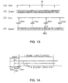
- Figs. 13(A) to (D) are schematic diagram explaining the operation of the memory circuit according to the second embodiment on coded data that has been subjected to switching on the basis of the frames of a video signal.
- Fig. 14 is a schematic diagram showing how coded blocks filled in one frame overlap original frames according to the second embodiment.
- Fig. 1, 1 generally indicates an audio signal encoder that is provided in, for example, a sound signal recording section in a digital video tape recorder.
- Input audio signals S AUD sampled at a frequency of 48 [kHz] and block pulse signals S BLK each comprising a pulse signal that rises every 384T of audio block length (T represents a sampling period of 20.8 [ ⁇ sec] at a sampling frequency of 48 [kHz]) are input to an MPEG coding circuit 2.
- the MPEG coding circuit 2 sub-band codes an input audio signal S AUD in blocks in synchronism with a block pulse signal S BLK based on the MPEG's sound standard MPEG layer I. This allows one sub-band coded block to be formed every 384 samples in input audio data, and coded data S CODE1 obtained is supplied to a memory circuit 3.
- the MPEG coding circuit 2 blocks the input audio signal S AUD (Fig. 2(B)) by dividing it into data units in synchronism with the block pulse signal S BLK (Fig. 2(A)), and sub-band codes each blocked data to generate the coded data S CODE1 (Fig. 2(C)) separated into blocks, as shown in Figs. 2(A) to (C).
- the coded data S CODE1 is output after a delay corresponding to the time T LG required for coding.
- the block pulse signal S BLK is input to a phase comparison circuit 4 together with a frame pulse signal S FLP .
- the frame pulse signal S FLP has a period that allows the video signal frame frequency of 29.97 [Hz] to be in synchronism with the input audio signal S AUD sampling frequency of 48 [kHz], and comprises an array of pulses that rise at a time interval of 1601T or 1602T.
- the phase comparison circuit 4 sets a window period W with a width of 384T (selected to have a length corresponding to one cycle of the block pulse S BLK ) before and after a rising time position of a frame pulse signal S FLP (Fig. 3(A)), and detects a block pulse signal S BLK (Fig. 3(B)) that rises within the window period W to detect the block number and amount of offset T OFF of a leading block BK1, as shown in Figs. 3(A) and (B).
- the phase comparison circuit 4 compares the phases of the block pulse signal S BLK and the frame pulse signal S FLP to detect a coded block located at a boundary between video frames, outputs to the memory circuit 3 a leading block detection signal S2 representing the block number of the detected block, and outputs to an offset addition circuit 5 an offset signal S3 including the amount of offset (a phase difference) of the leading block BK1 from the frame boundary and information on whether or not the leading block BK1 is a duplicate of the preceding coded block.
- the phase comparison circuit 4 can thus output to the memory circuit 3 a leading block detection signal S2 representing the block starting at the block pulse S BLK (Fig. 3(B)) that rises within the window period W.
- the window period W with a width of 384T is set from -351T to +32T using the rising position of the frame pulse S FLP as the reference.
- the memory circuit 3 sequentially stores input coded data S CODE1 (Fig. 4(B)) from the MPEG coding circuit 2 asynchronously with the phase of the frame pulse signal S FLP (Fig. 4(A)), as shown in Figs. 4(A) to (D).
- the memory circuit 3 starts reading the leading block BK1 at the rising of a code frame pulse signal S CFP (Fig. 4(C)) and reads coded data S CODE2 (Fig. 4(D)) at a high speed sufficient to fill an integral number of coded blocks in one frame in order to output the output coded data S CODE2 in synchronism with the code frame pulse signal S CFP (Fig. 4(C)).
- the code frame pulse signal S CFP indicates the output phase of coded audio data S CODE3 output on the basis of frames, and rises at an interval of 1601T or 1602T as in the frame pulse signal S FLP .
- the audio data thus written to the memory circuit 3 as the coded data S CODE1 asynchronously with the video frame is read out as the coded data S CODE2 synchronizing with the video frame and comprising audio block data including the leading block and an integral number of subsequent blocks (for example, 5 blocks in total) which are filled in one video frame.
- the memory circuit 3 reads the audio data at a high speed 5/(1601.6/384) times as high as the speed at which the data is written in order to fill five blocks of audio data in one video frame.
- the value of 1601.6 indicates the number of audio data samples in one video frame, and is the average obtained from generation probability of the numbers of video data samples (that is, 1601 and 1602 samples).
- a single read of audio data from the memory circuit 3 may be insufficient to read audio data of as many samples as those in one video frame as output coding data S CODE2 , so the memory circuit 3 also reads the data in audio blocks corresponding to an insufficient number of samples (in this embodiment, the data in the fifth audio block from leading block BK1) at the terminal of the one video frame period in a duplicate manner.
- Whether or not audio blocks are read from the memory circuit 3 in a duplicate manner is determined by the phase comparison circuit 4 detecting whether or not the leading position of the fifth block from the detected leading block BK1 is within the window period W. On determining that the leading position of the fifth block from the leading block BK1 is within the window period W, the phase comparison circuit 4 controls the memory circuit 3 so as to also read the fifth block based on a leading block examination signal S2 in a duplicate manner. When, however, the leading position of the fifth audio block from the leading block BK1 is not within the window period W, a duplicate read is not executed.
- An offset addition circuit 5 adds an offset signal S3 to the beginning of each frame (or the beginning of each coded block) as header information to form final coded audio data S CODE3 , which is transmitted to the recording section of the digital VTR and recorded on the recording medium.
- the coded audio data S CODE3 reproduced from the recording medium by the reproduction section of the digital VTR, is decoded by an audio signal decoder 10 as shown in Fig. 5.
- the audio signal decoder 10 sequentially stores in the memory circuit 11 the coded audio data S CODE3 transmitted from the reproduction section of the digital VTR, and also inputs it to an offset extraction circuit 12.
- the offset extraction circuit 12 extracts the offset signal S3 added to the beginning of each frame (or the beginning of each coded block) based on the block pulse signal S BLK or code frame pulse signal S CFP , and outputs the offset signal S3 to a phase calculation circuit 13.
- the phase calculation circuit 13 receives the offset signal S3 and the frame pulse signal S FLP in synchronism with the frames of the video signals, uses the frame pulse signal S FLP as the reference to calculate a leading block phase signal S4 representing the phase of the leading block, and outputs the signal S4 to the memory circuit 11.
- the memory circuit 11 on loading the coded audio data S CODE3 (Fig. 6(B)) in synchronism with the code frame pulse signal S CFP (Fig. 6(A)), the memory circuit 11 reads each coded block, which has been offset during coding in synchronism with the frame pulse signal S FLP (Fig. 6(C)), so as to offset it an offset amount T OFF to return it to its original position, based on the leading block phase signal S4 supplied by the phase calculation circuit 13. The memory circuit 11 then outputs the coded block as coded audio data S CODE4 (Fig. 6(D)). At this point, only one of the duplicate blocks is read from the memory circuit 11 as the coded block specified by the offset signal, based on duplicate information.
- the audio signal decoder 10 enables the obtainment of the coded audio data S CODE4 comprising coded block data obtained by recovering, during a read from the memory circuit 11, the original block phases of the coded blocks converted so as to synchronize with the frame pulse signal S FLP by the memory circuit 3 of the audio signal encoder 1.
- the audio signal decoder 10 uses the MPEG decoding circuit 14 to decode the coded audio data S CODE4 , delays it a specified amount of time to allow it to synchronize with the video signal, and outputs it as a decoded audio signal S5.
- the input audio signal S AUD sampled at 48 [kHz] is block coded by the MPEG coding circuit 2 of the audio signal encoder 1 every 384 samples according to the MPEG's sound standard MPEG layer I.
- the coded blocks are stored in the memory circuit 3, and the timing with which and the speed at which data is read from the memory circuit 3 are controlled so as to fill an integral number of audio blocks in one video frame period, thereby forming the coded data S CODE2 in synchronism with the frames of the video signal.
- the coded audio data S CODE3 formed in this manner is directly, on the basis of frames of the video signal, subjected to switching such as edition and then decoded by the audio signal decoder 10.
- the coded audio data S CODE3 obtained from the audio signal coding circuit 1 comprises an integral number of coded blocks filled in the period of time corresponding to each video frame, thereby preventing the coded block from extending across video frames.
- each coded block is prevented from being separated at a switching point, and audio data can be decoded without causing decoded data to be missing near the switching point.
- the audio signal decoder 10 After controlling the read from the memory circuit 11 according to the offset signal S3 so as to recover the original phases of the coded blocks which have been offset during coding, the audio signal decoder 10 uses the MPEG decoding circuit 14 to decode the audio data.
- the period of time in which data is missing is only 383T, which means that the missing of data can be substantially reduced compared to the conventional technique in which the entire data in the blocks of 766 samples and relevant 256 samples located before and after these samples cannot be decoded because information cannot be obtained for decoding the audio data.
- an integral number of coded blocks are filled and transmitted in the period of time corresponding to one frame of the video signal. This prevents the coded audio block from extending beyond a frame boundary in the video signal, and also prevents audio data from being missing during decoding even if switching is carried out on the basis of video frames.
- the phase can be managed more easily during decoding because that amount of the offset of the coded block from a frame boundary which has been used during coding when the phase of the coded block has been aligned with the phase of the frame is added to the coded audio data and because this amount of offset is referenced to recover the original phase relationship during decoding.
- FIG. 9 in which the same components as in Fig. 1 have the same reference numerals, 20 indicates an audio signal encoder according to a second embodiment.
- a memory circuit 21 forms coded data S CODE2 ' comprising coded blocks in synchronism with the frames of the video signal by filling six coded audio blocks in the period of time corresponding to one frame of the video signal, thereby forming the coded data S CODE2 ', as shown in Fig. 10(D).
- the audio signal encoder 20 sets a window period W of a length equal to the width of one coded block including the frame pulse signal S FLP , and using as the leading block BK1 the coded block occurring within the window period W to align the audio block boundary position of the leading block BK1 with the corresponding video frame boundary position.
- the audio signal encoder 20 then arranges the coded blocks in such a manner that six audio blocks including the leading block BK1 are filled in the period of time corresponding to one video frame.
- the audio signal encoder 20 also writes the output of the MPEG coding circuit 2 to a memory circuit 21, and reads audio data for six blocks based on the leading block detection signal S2 from the phase comparator 4, as shown in Figs. 10(A) to (D). In this case, when the fifth audio block from the leading block is within the window period W, it is read in a duplicate manner, whereas when it is not within the window period W, it is not read in a duplicate manner.
- the sixth block BK2 is always read in a duplicate manner.
- the audio signal encoder 20 can reliably transmit audio data corresponding to each video block without the missing of data even if transmitted audio data is subjected to switching such as edition on the basis of video blocks.
- FIG. 11 in which the same components as in Fig. 5 have the same reference numerals, 30 indicates an audio signal decoder according to the second embodiment which temporarily stores in a memory circuit 31 coded audio data S CODE3 ' formed by the audio signal encoder 20, and which controls the read from memory circuit 31 based on the leading block phase signal S4 output from the phase calculation circuit 13 to output from the memory circuit 31 coded audio data S CODE4 ' with its original phase relationship with the video signal as shown in Figs. 12(A) to (D).
- the coded audio data S CODE3 ' is input to the audio signal decoder 30 in the same array as coded by the audio signal encoder 20, so the audio data in all the blocks is completely decoded as in the first embodiment.
- coded blocks each extending beyond a video frame boundary to overlap a plurality of video frames are assigned so as to be filled in the period of time corresponding to one video frame, as shown in Fig. 14.
- all the coded blocks in the frame can be decoded even if the coded audio data S CODE3 ' subjected to switching as shown in Fig. 13(B) is received.
- Even with a single decoder almost all the coded blocks in the frame can be decoded by enabling all six blocks to be decoded within the period of time corresponding to one video frame of 1601T or 1602T.
- the audio signal encoder 20 fills in one video frame of the video signal six blocks of coded audio data which completely cover each video frame in the period of time corresponding to one video frame in order to form coded audio data S CODE3 ' in which one or more audio blocks are read in a duplicate manner before and after the code frame pulse S CFP .
- the audio block data is subjected to switching on the basis of video frames, one of the duplicate audio block data can be decoded to reduce audio blocks that cannot be decoded, thereby enabling reliable decoding.
- This invention is applicable to video signal processing apparatuses that transmit (record, reproduce, and send through a transmission path) video signals and audio signals corresponding to the video signals together.
Landscapes
- Engineering & Computer Science (AREA)
- Multimedia (AREA)
- Signal Processing (AREA)
- General Engineering & Computer Science (AREA)
- Computational Linguistics (AREA)
- Health & Medical Sciences (AREA)
- Audiology, Speech & Language Pathology (AREA)
- Human Computer Interaction (AREA)
- Physics & Mathematics (AREA)
- Acoustics & Sound (AREA)
- Compression Or Coding Systems Of Tv Signals (AREA)
Abstract
Description
Claims (12)
- An audio signal coding method for coding an input audio signal (SAUD) corresponding to a video signal on the basis of specified data units to form coded audio data (SCODE1) separated into coded blocks, said method comprising:blocking and coding said input audio signal (SAUD) in specified data units to form said coded Mocks separated into blocks and writing the coded blocks sequentially to a memory means (3);aligning the leading position of one of said coded blocks with a corresponding frame or field boundary in said video signal, and forming said array of coded blocks in synchronism with the frames or fields of said video signal by arranging those coded blocks which follow the coded block the leading position of which has been aligned with the corresponding frame or field boundary in such a way that an integral number of said coded blocks are filled in the period of time corresponding to one frame or field, thereby reading the data (SCODE2) from said memory means (3); andadding to said coded audio data (SCODE2), information representing the phase difference (S3) between said frame or field boundary position and said coded block not subjected to alignment of its block leading position with said frame or field boundary position, wherein;said written coded audio data (SCODE2) is read at a higher read speed than a write speed and in synchronism with one frame or field of said video signal.
- The audio signal coding method according to claim 1 wherein:said video signal has 525 scanning lines per frame and a field frequency of 59.94 [Hz], wherein:said input audio signal (SAUD) is sampled at 48 [kHz], and wherein:said coded block is obtained by coding said input audio signal (SAUD) on the basis of the data unit of 384 samples.
- The audio signal coding method according to claim 1 wherein:five coded blocks are filled in the period of time corresponding to said one frame or field.
- The audio signal coding method according to claim 1 wherein:six coded blocks are filled in the period of time corresponding to said one frame or field.
- The audio signal coding method according to claim 4 wherein:for at least one of the coded blocks to be filled in said one frame or field, only part of the bit stream therein is filled.
- An audio signal encoder (1) for coding an input audio signal (SAUD) corresponding to a video signal on the basis of specified data units to form coded audio data (SCODE1) separated into coded blocks, comprising:coding means (2) for blocking and coding said input audio signal (SAUD) in specified data units to form coded blocks separated into blocks and outputting the coded blocks as audio data (SCODE1);detection means (4) for determining the phase difference between the frame or field boundaries in said video signal and said coded blocks in said audio data (SCODE1) to detect the coded block corresponding to a particular frame or field boundary based on the phase difference;memory means (3) operative after the write of said audio data (SCODE1) from said coding means (2) for aligning, based on the results of detection by said detection means (4), the block leading position of the coded block with a corresponding frame or field boundary, and outputting an array of coded blocks in synchronism with the frames or fields of the video signal by reading said written audio data (SCODE2) to arrange those coded blocks which follow the coded block the leading position of which has been aligned with the corresponding frame or field boundary in such a way that an integral number of coded blocks are filled in the period of time corresponding to one frame or field; andphase difference addition means (5) for adding the phase difference detected by said detection means (4) to said coded block in synchronism with the frame or field which is output from said memory means (3).
- The audio signal encoder (1) according to claim 6 wherein:said video signal has 525 scanning lines per frame and a field frequency of 59.94 [Hz], wherein:said input audio signal (SAUD) is sampled at 48 [kHz], and wherein:said coded block is formed by coding said input audio signal (SAUD) on the basis of the data unit of 384 samples.
- The audio signal encoder (1) according to claim 6 wherein:five coded blocks are filled by said memory means (3) in the period of time corresponding to said one frame or field.
- The audio signal encoder (1) according to claim 6 wherein:six coded blocks are filled by said memory means (3) in the period of time corresponding to said one frame or field to be arranged for outputting.
- The audio signal encoder (1) according to claim 9 wherein:for at least one of the coded blocks to be filled in the period of time corresponding to said one frame or field, only part of the bit stream therein is filled.
- An audio signal coding and decoding method comprising the audio signal coding steps of claim 1; and
coded audio data (SCODE3) decoding steps including the steps of:writing said coded audio data (SCODE3) to a second memory means (11);detecting relevant phase difference information (S3) from the coded audio data (SCODE3) including said information on the phase difference (S3); andreading data (SCODE4) from said second memory means (11) based on the detected phase difference information (S3) to recover the original phase relationship between said coded block and said video signal. - An audio signal encoder and decoder comprising an audio signal encoder (1) according to claim 6; and
a coded audio data (SCODE3) decoding section (10) including:phase difference information (S3) detection means (12) for detecting said phase difference information (S3) from the coded audio data (SCODE3) from said audio signal coding section (1); andsecond memory means (11) operative after the write of the coded audio data (SCODE3) from said audio signal encoder (1) for reading the written coded audio data (SCODE4) based on the phase difference information (S3) detected by said phase difference information detection means (12) in order to recover the original phase relationship between said coded block and said video signal.
Applications Claiming Priority (4)
| Application Number | Priority Date | Filing Date | Title |
|---|---|---|---|
| JP15861795 | 1995-05-31 | ||
| JP15861795 | 1995-05-31 | ||
| JP158617/95 | 1995-05-31 | ||
| PCT/JP1996/001490 WO1996038843A1 (en) | 1995-05-31 | 1996-05-31 | Method and device for encoding audio signal and method and device for decoding audio signal |
Publications (3)
| Publication Number | Publication Date |
|---|---|
| EP0829875A1 EP0829875A1 (en) | 1998-03-18 |
| EP0829875A4 EP0829875A4 (en) | 2000-04-19 |
| EP0829875B1 true EP0829875B1 (en) | 2002-09-18 |
Family
ID=15675631
Family Applications (1)
| Application Number | Title | Priority Date | Filing Date |
|---|---|---|---|
| EP96920030A Expired - Lifetime EP0829875B1 (en) | 1995-05-31 | 1996-05-31 | Method and device for encoding audio signal and method and device for decoding audio signal |
Country Status (4)
| Country | Link |
|---|---|
| US (1) | US6480234B1 (en) |
| EP (1) | EP0829875B1 (en) |
| DE (1) | DE69623771T2 (en) |
| WO (1) | WO1996038843A1 (en) |
Families Citing this family (14)
| Publication number | Priority date | Publication date | Assignee | Title |
|---|---|---|---|---|
| US6124895A (en) * | 1997-10-17 | 2000-09-26 | Dolby Laboratories Licensing Corporation | Frame-based audio coding with video/audio data synchronization by dynamic audio frame alignment |
| US5913190A (en) * | 1997-10-17 | 1999-06-15 | Dolby Laboratories Licensing Corporation | Frame-based audio coding with video/audio data synchronization by audio sample rate conversion |
| DE19849408A1 (en) * | 1998-10-27 | 2000-05-04 | Continental Teves Ag & Co Ohg | Method and device for processing a received signal that transmits data in coded form |
| US6639878B1 (en) * | 2000-03-21 | 2003-10-28 | Microsoft Corporation | Method and apparatus for characterizing and improving optical drive performance |
| EP1449365A2 (en) * | 2001-07-09 | 2004-08-25 | Visible World, Inc. | System and method for seamless switching of compressed audio streams |
| JP4467984B2 (en) * | 2002-01-18 | 2010-05-26 | コーニンクレッカ フィリップス エレクトロニクス エヌ ヴィ | Audio coding |
| US7006976B2 (en) | 2002-01-29 | 2006-02-28 | Pace Micro Technology, Llp | Apparatus and method for inserting data effects into a digital data stream |
| US7174696B2 (en) | 2002-03-01 | 2007-02-13 | Free-Flow Packaging International, Inc. | Machine and method for inflating and sealing air-filled packing cushions |
| JP4340483B2 (en) * | 2003-06-27 | 2009-10-07 | 富士通株式会社 | Composite content delivery method and delivery system |
| JP4979355B2 (en) * | 2006-11-30 | 2012-07-18 | パナソニック株式会社 | Image coding apparatus and image coding method |
| JP4948147B2 (en) | 2006-12-15 | 2012-06-06 | 富士通株式会社 | Method and apparatus for editing composite content file |
| DE102009030318B4 (en) * | 2009-06-24 | 2012-09-06 | Opticom Dipl.-Ing. Michael Keyhl Gmbh | Apparatus and method for determining a sample rate difference |
| GB2477263B (en) * | 2010-01-13 | 2015-09-30 | British Broadcasting Corp | Method and apparatus for processing transport streams |
| FR2987197B1 (en) * | 2012-02-20 | 2015-11-20 | Tdf | METHOD FOR GENERATING A DIGITAL PACKET STREAM OUT OF AN ENCODER, DEVICE CAPABLE OF GENERATING SUCH AN ENCODED STREAM AND A SYSTEM SUITABLE FOR USING SUCH AN ENCODED STREAM. |
Citations (5)
| Publication number | Priority date | Publication date | Assignee | Title |
|---|---|---|---|---|
| JPS60212874A (en) * | 1984-04-09 | 1985-10-25 | Matsushita Electric Ind Co Ltd | Digital signal recording and reproducing device |
| EP0178075A1 (en) * | 1984-09-17 | 1986-04-16 | Sony Corporation | Methods of recording and reproducing audio signals |
| EP0239326A2 (en) * | 1986-03-19 | 1987-09-30 | Victor Company Of Japan, Limited | Magnetic recording and reproducing system |
| JPS63131375A (en) * | 1986-11-21 | 1988-06-03 | Matsushita Electric Ind Co Ltd | Rotary head type recording and reproducing device |
| EP0315372A2 (en) * | 1987-10-31 | 1989-05-10 | Sony Corporation | Digital signal recording apparatus |
Family Cites Families (7)
| Publication number | Priority date | Publication date | Assignee | Title |
|---|---|---|---|---|
| US4851409A (en) * | 1986-02-14 | 1989-07-25 | Merck Frosst Canada Inc. | 2-substituted quinoline dioic acids and pharmaceutical compositions |
| DE69321558T2 (en) * | 1992-11-17 | 1999-04-22 | Matsushita Electric Industrial Co., Ltd., Kadoma, Osaka | Video and audio signal multiplexing and separating devices |
| JP2630202B2 (en) * | 1993-06-16 | 1997-07-16 | 松下電器産業株式会社 | Recording device |
| US5351092A (en) * | 1993-07-23 | 1994-09-27 | The Grass Valley Group, Inc. | Synchronization of digital audio with digital video |
| DE69414275T2 (en) * | 1993-09-16 | 1999-05-06 | Toshiba Kawasaki Kk | Device for synchronizing compressed video and audio signals |
| JP3500671B2 (en) * | 1993-10-08 | 2004-02-23 | ソニー株式会社 | Digital image signal recording and / or reproducing method, recording and / or reproducing apparatus, and recording medium |
| US5483538A (en) * | 1994-05-25 | 1996-01-09 | The Grass Valley Group, Inc. | Audio frame synchronization for embedded audio demultiplexers |
-
1996
- 1996-05-31 DE DE69623771T patent/DE69623771T2/en not_active Expired - Fee Related
- 1996-05-31 EP EP96920030A patent/EP0829875B1/en not_active Expired - Lifetime
- 1996-05-31 WO PCT/JP1996/001490 patent/WO1996038843A1/en active IP Right Grant
-
1997
- 1997-11-28 US US08/979,634 patent/US6480234B1/en not_active Expired - Fee Related
Patent Citations (5)
| Publication number | Priority date | Publication date | Assignee | Title |
|---|---|---|---|---|
| JPS60212874A (en) * | 1984-04-09 | 1985-10-25 | Matsushita Electric Ind Co Ltd | Digital signal recording and reproducing device |
| EP0178075A1 (en) * | 1984-09-17 | 1986-04-16 | Sony Corporation | Methods of recording and reproducing audio signals |
| EP0239326A2 (en) * | 1986-03-19 | 1987-09-30 | Victor Company Of Japan, Limited | Magnetic recording and reproducing system |
| JPS63131375A (en) * | 1986-11-21 | 1988-06-03 | Matsushita Electric Ind Co Ltd | Rotary head type recording and reproducing device |
| EP0315372A2 (en) * | 1987-10-31 | 1989-05-10 | Sony Corporation | Digital signal recording apparatus |
Non-Patent Citations (2)
| Title |
|---|
| PATENT ABSTRACTS OF JAPAN vol. 010, no. 074 (P - 439) 25 March 1986 (1986-03-25) * |
| PATENT ABSTRACTS OF JAPAN vol. 012, no. 390 (P - 772) 18 October 1988 (1988-10-18) * |
Also Published As
| Publication number | Publication date |
|---|---|
| DE69623771T2 (en) | 2003-07-31 |
| EP0829875A4 (en) | 2000-04-19 |
| EP0829875A1 (en) | 1998-03-18 |
| WO1996038843A1 (en) | 1996-12-05 |
| DE69623771D1 (en) | 2002-10-24 |
| US6480234B1 (en) | 2002-11-12 |
Similar Documents
| Publication | Publication Date | Title |
|---|---|---|
| US5953483A (en) | Apparatus for recording and reproducing an information signal comprising packets that may occur irregularly as a function of time in a serial datastream of the information signal, and a record carrier carrying the information signal | |
| EP1175103B1 (en) | Recording and reproducing an MPEG information signal on/from a record carrier | |
| EP0829875B1 (en) | Method and device for encoding audio signal and method and device for decoding audio signal | |
| JP3047812B2 (en) | Magnetic recording / reproducing device | |
| EP0116402A2 (en) | Scrambling systems for audio frequency signals | |
| KR100293859B1 (en) | Digital video signal encoding device | |
| JP3158740B2 (en) | Digital video signal transmission method and dubbing method | |
| US5717815A (en) | Compression data editing apparatus | |
| US5999905A (en) | Apparatus and method for processing data to maintain continuity when subsequent data is added and an apparatus and method for recording said data | |
| RU2219655C2 (en) | Device and method for transmitting digital information signal, record medium, and signal receiving device | |
| US5889917A (en) | Method and apparatus for editing an audio-visual signal having audio data that is in the form of block units which are not synchronous with the fields/frames of video data | |
| EP0726679B1 (en) | Method and device for transmitting compressed picture data | |
| WO1996033559A2 (en) | Concealment method and arrangement and reproducing apparatus provided with the concealment arrangement | |
| KR100456176B1 (en) | Video data recording and / or playback device and video data recording and / or playback method | |
| JP3646382B2 (en) | Data processing apparatus, data processing method, data recording apparatus, data recording method, encoding apparatus, and encoding method | |
| EP0996128A2 (en) | Method and apparatus for recording and reproducing information | |
| US6289171B1 (en) | Arrangement for recording or reproducing a digital video signal and a corresponding digital audio signal | |
| JP2666793B2 (en) | Receiving-side timing reproduction method and apparatus | |
| US6038370A (en) | Recording and/or reproducing device and its method | |
| KR0179113B1 (en) | Audio dubbing and reproduction method and apparatus for dvcr | |
| KR100220848B1 (en) | Audio channel inserting apparatus for a digital video camera | |
| JP3430613B2 (en) | Information signal reproducing method and apparatus | |
| JPH10198400A (en) | Data coding device and method, data decoding device and method, and data coding and decoding system | |
| JPH08329605A (en) | Method and device for processing digital audio signal and recording/reproducing device | |
| JPH11219564A (en) | Recording device and recording and reproducing device |
Legal Events
| Date | Code | Title | Description |
|---|---|---|---|
| PUAI | Public reference made under article 153(3) epc to a published international application that has entered the european phase |
Free format text: ORIGINAL CODE: 0009012 |
|
| 17P | Request for examination filed |
Effective date: 19971119 |
|
| AK | Designated contracting states |
Kind code of ref document: A1 Designated state(s): DE FR GB |
|
| A4 | Supplementary search report drawn up and despatched |
Effective date: 20000302 |
|
| AK | Designated contracting states |
Kind code of ref document: A4 Designated state(s): DE FR GB |
|
| RIC1 | Information provided on ipc code assigned before grant |
Free format text: 7G 11B 20/12 A, 7H 04N 5/91 B, 7H 04N 9/806 B |
|
| 17Q | First examination report despatched |
Effective date: 20010212 |
|
| GRAG | Despatch of communication of intention to grant |
Free format text: ORIGINAL CODE: EPIDOS AGRA |
|
| GRAG | Despatch of communication of intention to grant |
Free format text: ORIGINAL CODE: EPIDOS AGRA |
|
| GRAG | Despatch of communication of intention to grant |
Free format text: ORIGINAL CODE: EPIDOS AGRA |
|
| GRAH | Despatch of communication of intention to grant a patent |
Free format text: ORIGINAL CODE: EPIDOS IGRA |
|
| GRAH | Despatch of communication of intention to grant a patent |
Free format text: ORIGINAL CODE: EPIDOS IGRA |
|
| GRAA | (expected) grant |
Free format text: ORIGINAL CODE: 0009210 |
|
| AK | Designated contracting states |
Kind code of ref document: B1 Designated state(s): DE FR GB |
|
| REG | Reference to a national code |
Ref country code: GB Ref legal event code: FG4D |
|
| REF | Corresponds to: |
Ref document number: 69623771 Country of ref document: DE Date of ref document: 20021024 |
|
| ET | Fr: translation filed | ||
| PGFP | Annual fee paid to national office [announced via postgrant information from national office to epo] |
Ref country code: FR Payment date: 20030508 Year of fee payment: 8 |
|
| PGFP | Annual fee paid to national office [announced via postgrant information from national office to epo] |
Ref country code: GB Payment date: 20030528 Year of fee payment: 8 |
|
| PGFP | Annual fee paid to national office [announced via postgrant information from national office to epo] |
Ref country code: DE Payment date: 20030612 Year of fee payment: 8 |
|
| PLBE | No opposition filed within time limit |
Free format text: ORIGINAL CODE: 0009261 |
|
| STAA | Information on the status of an ep patent application or granted ep patent |
Free format text: STATUS: NO OPPOSITION FILED WITHIN TIME LIMIT |
|
| 26N | No opposition filed |
Effective date: 20030619 |
|
| PG25 | Lapsed in a contracting state [announced via postgrant information from national office to epo] |
Ref country code: GB Free format text: LAPSE BECAUSE OF NON-PAYMENT OF DUE FEES Effective date: 20040531 |
|
| PG25 | Lapsed in a contracting state [announced via postgrant information from national office to epo] |
Ref country code: DE Free format text: LAPSE BECAUSE OF NON-PAYMENT OF DUE FEES Effective date: 20041201 |
|
| GBPC | Gb: european patent ceased through non-payment of renewal fee | ||
| PG25 | Lapsed in a contracting state [announced via postgrant information from national office to epo] |
Ref country code: FR Free format text: LAPSE BECAUSE OF NON-PAYMENT OF DUE FEES Effective date: 20050131 |
|
| REG | Reference to a national code |
Ref country code: FR Ref legal event code: ST |