EP0829814B1 - An optical code hand-reader - Google Patents
An optical code hand-reader Download PDFInfo
- Publication number
- EP0829814B1 EP0829814B1 EP96830473A EP96830473A EP0829814B1 EP 0829814 B1 EP0829814 B1 EP 0829814B1 EP 96830473 A EP96830473 A EP 96830473A EP 96830473 A EP96830473 A EP 96830473A EP 0829814 B1 EP0829814 B1 EP 0829814B1
- Authority
- EP
- European Patent Office
- Prior art keywords
- hand
- held reader
- mirror
- reader
- shell
- Prior art date
- Legal status (The legal status is an assumption and is not a legal conclusion. Google has not performed a legal analysis and makes no representation as to the accuracy of the status listed.)
- Expired - Lifetime
Links
Images


Classifications
-
- G—PHYSICS
- G06—COMPUTING OR CALCULATING; COUNTING
- G06K—GRAPHICAL DATA READING; PRESENTATION OF DATA; RECORD CARRIERS; HANDLING RECORD CARRIERS
- G06K7/00—Methods or arrangements for sensing record carriers, e.g. for reading patterns
- G06K7/10—Methods or arrangements for sensing record carriers, e.g. for reading patterns by electromagnetic radiation, e.g. optical sensing; by corpuscular radiation
- G06K7/10544—Methods or arrangements for sensing record carriers, e.g. for reading patterns by electromagnetic radiation, e.g. optical sensing; by corpuscular radiation by scanning of the records by radiation in the optical part of the electromagnetic spectrum
- G06K7/10821—Methods or arrangements for sensing record carriers, e.g. for reading patterns by electromagnetic radiation, e.g. optical sensing; by corpuscular radiation by scanning of the records by radiation in the optical part of the electromagnetic spectrum further details of bar or optical code scanning devices
- G06K7/10881—Methods or arrangements for sensing record carriers, e.g. for reading patterns by electromagnetic radiation, e.g. optical sensing; by corpuscular radiation by scanning of the records by radiation in the optical part of the electromagnetic spectrum further details of bar or optical code scanning devices constructional details of hand-held scanners
Definitions
- the present invention relates to a hand-held reader of an optical code.
- optical code it is intended to indicate a set of graphic signs (placed either on a label or directly on a product or on any other support) by means of which a piece of information is coded as a sequence of white areas and black areas or areas of various colours, arranged along one or more directions. Examples of such codes are bar codes, two-dimensional codes, colour codes and others.
- optical codes can take place by means of fixed or hand-held readers (reading devices).
- the latter are provided with a reading casing (or shell) with a window (or mouth) through which there are active both means that illuminate the code to be read, and means that read the image of the illuminated code detecting the light diffused by it and transforming it into electrical signals.
- a reader of this type is known - for example - from EP-A-0488202 which is used for the two-part form delimitation. It is provided with a shell with an angled shape that allows it to be handled in an ergonomic manner and that has, along the optical path, a mirror capable of directing the light diffused by the code on a photoelectric transducer.
- the photo-electric transducer emits an electrical signal that is sent to a data processing circuit capable of decoding the information contained in the optical code.
- the mirror is mounted and fastened (e.g. by means of screws) in a special seat of the shell.
- EP-A-0590537 discloses an optical scanner for reading bar codes in which scanning is performed by directing a laser beam onto a vibrating mirror; reciprocal movement of the mirror causes alternate deflection of the laser beam. Such mirror is supported in the casing of the device by elastic means that permit the reciprocal movement of the mirror.
- the object of the present invention is to simplify the assembling of a hand-held reader of an optical code and to make the constraint of the mirror in the shell more secure.
- the mirror is mounted elastically in the shell by means of the spring element and, when the reader falls down, it can move freely with respect to the shell, but without leaving its seat. Thus, it does not break and it automatically retums to the correct position, avoiding misalignments in the optical path of the beam of diffused light.
- just one component formed by the spring element performs several functions: it acts as a fastening and positioning means of the mirror in the shell and it serves as a shock absorber when the reader falls down.
- a hand-held reader of an optical code comprising an angled shell 2 formed by a lower casing 21 and by an upper cover 22.
- the shell 2 is provided with a mouth 3 containing a conventional focusing lens, not shown.
- the focusing lens serves to concentrate a beam of light emitted by diodes, not shown, on an optical code present on a label or on a product, both also not shown, and to direct a beam of light diffused by the label or by the product on a mirror 4.
- the mirror 4 directs the beam of light to a conventional opto-electric transducer, not shown, operationally connected to a data processing circuit, also not shown, that decodes the information contained in the optical code.
- the mirror 4 is mounted elastically in two walls 5 supporting the lower casing 21 by means of a spring element 6.
- the (elastic) spring element 6 is formed by a central plate 61 provided with two folded-over portions 62 that form a seat 63 capable of housing the mirror 4.
- the central plate 61 is also provided with two fins 64 protruding laterally, having a substantially "L"-shaped transversal cross-section.
- Each of the fins 64 comprises two portions, 65 and 66, respectively.
- the portion 65 is inclined with respect to the plate 61 by an angle ⁇ less than 180°, preferably an angle ranging from 175° to 150°, so that it remains raised with respect to the mirror 4, and terminates with an upper part 68.
- the portion 66 is folded over with respect to the portion 65 by an angle ⁇ less than 90°, preferably ranging from 75° to 50°.
- the portions 66 are provided with respective slots 67 capable of engaging in a self-centering and disconnectable manner projections 51 with which the walls 5 are provided.
- the slots 67 and the projections 51 have a triangular shape, but they can have a different shape, for instance like a trapeze, a semicylinder and such like, as long as they are self-centering.
- the spring element 6 is snap-fastened to the walls 5 by connecting the slots 67 to the projections 51.
- the cover 22 is provided with two protruding tangs 7 that act as limit stop for the fins 64 when the reader 1 falls down.
- the tangs 7 are arranged opposite the upper part 68 of the portions 65 (Fig. 2) and have dimension such that, under the reader's normal operating conditions, there is no contact between them and the upper part 68 of the portions 65.
- the distance between the tangs 7 and the upper part 68 of the portions 65 is such that, when the reader falls down or bumps, the spring element 6, being elastic, can move until the upper part 68 of the portions 65 comes into contact with the tangs 7. In this manner, the spring element 6 and the mirror 4, while falling down or is subjected to a bump, can move elastically and avoid the breakage of the mirror itself.
Landscapes
- Physics & Mathematics (AREA)
- Engineering & Computer Science (AREA)
- Electromagnetism (AREA)
- Artificial Intelligence (AREA)
- Toxicology (AREA)
- General Health & Medical Sciences (AREA)
- Health & Medical Sciences (AREA)
- Computer Vision & Pattern Recognition (AREA)
- General Physics & Mathematics (AREA)
- Theoretical Computer Science (AREA)
- Mechanical Optical Scanning Systems (AREA)
- Facsimile Heads (AREA)
- Holo Graphy (AREA)
- Light Guides In General And Applications Therefor (AREA)
Abstract
Description
- The present invention relates to a hand-held reader of an optical code.
- With the term optical code it is intended to indicate a set of graphic signs (placed either on a label or directly on a product or on any other support) by means of which a piece of information is coded as a sequence of white areas and black areas or areas of various colours, arranged along one or more directions. Examples of such codes are bar codes, two-dimensional codes, colour codes and others.
- The reading of optical codes can take place by means of fixed or hand-held readers (reading devices). The latter are provided with a reading casing (or shell) with a window (or mouth) through which there are active both means that illuminate the code to be read, and means that read the image of the illuminated code detecting the light diffused by it and transforming it into electrical signals.
- A reader of this type is known - for example - from EP-A-0488202 which is used for the two-part form delimitation. It is provided with a shell with an angled shape that allows it to be handled in an ergonomic manner and that has, along the optical path, a mirror capable of directing the light diffused by the code on a photoelectric transducer. The photo-electric transducer emits an electrical signal that is sent to a data processing circuit capable of decoding the information contained in the optical code.
- In such reader, the mirror is mounted and fastened (e.g. by means of screws) in a special seat of the shell.
- In other readers, between the seat and the mirror there is interposed a rubber gasket that has the object of avoiding misalignments and breakages when the reader falls down. A drawback, this, that occurs with great frequency as the readers are hand-held.
- Thus, the fastening of the mirror in its seat by means of screws and gasket involves the use of a fair number of components and this makes the operations of assembling the readers somewhat laborious. This involves increases in the readers' manufacturing costs.
- EP-A-0590537 discloses an optical scanner for reading bar codes in which scanning is performed by directing a laser beam onto a vibrating mirror; reciprocal movement of the mirror causes alternate deflection of the laser beam. Such mirror is supported in the casing of the device by elastic means that permit the reciprocal movement of the mirror.
- The object of the present invention is to simplify the assembling of a hand-held reader of an optical code and to make the constraint of the mirror in the shell more secure.
- The abovementioned object, according to the invention, is attained with a hand-held reader according to
claim 1. Dependent claims 2 to 3 set out particular embodiments of the invention. - In the reader of an optical code according to the invention, the mirror is mounted elastically in the shell by means of the spring element and, when the reader falls down, it can move freely with respect to the shell, but without leaving its seat. Thus, it does not break and it automatically retums to the correct position, avoiding misalignments in the optical path of the beam of diffused light.
- Thus, just one component formed by the spring element performs several functions: it acts as a fastening and positioning means of the mirror in the shell and it serves as a shock absorber when the reader falls down.
- Since the elastic mount of the mirror in the shell is executed by means of a single component, the assembling of the reader is considerably simplified, with a significant drop in manufacturing costs.
- Features and advantages of the invention will now be illustrated with reference to an embodiment represented as a non-limitative example in the enclosed drawings, wherein:
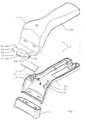
- Fig. 1 is a diagrammatic, exploded, view of a hand-held reader of an optical code, made according to the present invention;
- Fig. 2 is a partial, perspective, view, in an enlarged scale, of the reader of Fig. 1;
- Fig. 3 is a plan view from above of a spring element of the reader of Figs. 1 and 2;
- Fig. 4 is a side view of the spring element of Fig. 3;
- Fig. 5 is a cross-sectional view taken along the line V-V of Fig. 3.
-
- In Figs. 1 and 2 there is shown a hand-held reader of an optical code, indicated as a whole with 1, comprising an
angled shell 2 formed by alower casing 21 and by anupper cover 22. Theshell 2 is provided with amouth 3 containing a conventional focusing lens, not shown. The focusing lens serves to concentrate a beam of light emitted by diodes, not shown, on an optical code present on a label or on a product, both also not shown, and to direct a beam of light diffused by the label or by the product on amirror 4. Themirror 4, in turn, directs the beam of light to a conventional opto-electric transducer, not shown, operationally connected to a data processing circuit, also not shown, that decodes the information contained in the optical code. - The
mirror 4 is mounted elastically in twowalls 5 supporting thelower casing 21 by means of aspring element 6. - As also shown in Figs. 3-5, the (elastic)
spring element 6 is formed by acentral plate 61 provided with two folded-overportions 62 that form aseat 63 capable of housing themirror 4. Thecentral plate 61 is also provided with twofins 64 protruding laterally, having a substantially "L"-shaped transversal cross-section. Each of thefins 64 comprises two portions, 65 and 66, respectively. Theportion 65 is inclined with respect to theplate 61 by an angle α less than 180°, preferably an angle ranging from 175° to 150°, so that it remains raised with respect to themirror 4, and terminates with anupper part 68. Theportion 66 is folded over with respect to theportion 65 by an angle β less than 90°, preferably ranging from 75° to 50°. Theportions 66 are provided withrespective slots 67 capable of engaging in a self-centering anddisconnectable manner projections 51 with which thewalls 5 are provided. Theslots 67 and theprojections 51 have a triangular shape, but they can have a different shape, for instance like a trapeze, a semicylinder and such like, as long as they are self-centering. - After the
mirror 4 has been mounted in theseat 63 of thecentral plate 61, thespring element 6 is snap-fastened to thewalls 5 by connecting theslots 67 to theprojections 51. - The
cover 22 is provided with twoprotruding tangs 7 that act as limit stop for thefins 64 when thereader 1 falls down. Thetangs 7 are arranged opposite theupper part 68 of the portions 65 (Fig. 2) and have dimension such that, under the reader's normal operating conditions, there is no contact between them and theupper part 68 of theportions 65. The distance between thetangs 7 and theupper part 68 of theportions 65 is such that, when the reader falls down or bumps, thespring element 6, being elastic, can move until theupper part 68 of theportions 65 comes into contact with thetangs 7. In this manner, thespring element 6 and themirror 4, while falling down or is subjected to a bump, can move elastically and avoid the breakage of the mirror itself. But movements are limited avoiding the possibility that theslots 67 of thespring element 6 can become detached from theprojections 51 of the supportingwalls 5. The triangular shape of theslots 67 and of theprojections 51, moreover, cause thespring element 6 to reposition itself exactly in the correct position, after fall or bump.
Claims (16)
- A hand-held reader (1) of an optical code comprising diodes emitting light for illuminating said optical code, a shell (2), a mirror (4) mounted in the shell (2) in a predetermined working position and capable of deflecting light diffused by said optical code, characterized in that the mirror (4) is mounted in the shell (2) by means of a spring element (6), capable of elastically supporting said mirror (4) in said one predetermined working position with respect to said shell (2).
- A hand-held reader (1) according to claim 1, characterized in that the spring element (6) includes a central plate (61) housing said mirror (4) and two fins (64) protruding laterally from the central plate (61). each of said fins (64) being provided with connecting means (67) engaging a supporting element (5) integral with said shell (2).
- A hand-held reader (1) according to claim 2, characterized in that:the central plate (61) has a front surface supporting the mirror (4) and an opposite back surface;each of said fins (64) comprisesa first portion (65), inclined back from the back surface of the central plate (61) by a first preselected angle α, each of said first portions (65) remaining raised with respect to said mirror (4), anda second portion (66) folded over with respect to said first portion (65) towards said mirror (4) by a second preselected angle β.
- A hand-held reader (1) according to claim 2 or 3, characterized in that said connecting means (67) are capable of engaging said supporting element (5) in a disconnectable manner.
- A hand-held reader (1) according to any of claims 2 to 4, characterized in that said connecting means (67) of said fins (64) are capable of engaging their respective supporting elements (5) in a self-centering manner.
- A hand-held reader (1) according to claim 3, characterized in that said first angle α is less than 180°.
- A hand-held reader (1) according to claim 6, characterized in that said first angle α ranges from 175° to 150°
- A hand-held reader (1) according to claim 3, characterized in that said second angle β is less than 90°.
- A hand-held reader (1) according to claim 8, characterized in that said second angle β ranges from 75° to 50°.
- A hand-held reader (1) according to claim 3, characterized in that each of said second portions (66) of said fins (64) is provided with a slot (67) capable of engaging a respective projection (51) of said supporting element (5).
- A hand-held reader (1) according to claims 10, characterized in that each of said slots (67) is capable of engaging its respective projection (51) in a self-centering manner.
- A hand-held reader (1) according to claim 10, characterized in that said slot (67) is capable of snap-engageing said projection (51)
- A hand-held reader (1) according to any of claims 10 to 12, characterized in that said slot (67) and said projection (51) have a triangular shape.
- A hand-held reader (1) according to claim 2, characterized in that said central plate (61) has two folded-over portions (62) that form a seat (63) capable of housing said mirror (4).
- A hand-held reader (1) according to claim 2, characterized in that said shell (2) is provided with two protrusions (7) capable of acting as limit stop for said fins (64) when said reader (1) falls down or bumps so as to avoid the disconnection of said spring element (6) from said supporting elements (5).
- A hand-held reader (1) according to claim 15, characterized in that said protrusions (7) have dimensions such that they are normally spaced from said fins (64) and come into contact with them when said reader (1) falls down or bumps.
Priority Applications (4)
| Application Number | Priority Date | Filing Date | Title |
|---|---|---|---|
| EP96830473A EP0829814B1 (en) | 1996-09-17 | 1996-09-17 | An optical code hand-reader |
| AT96830473T ATE256891T1 (en) | 1996-09-17 | 1996-09-17 | PORTABLE OPTICAL CODE SCAN |
| DE69631129T DE69631129T2 (en) | 1996-09-17 | 1996-09-17 | Portable scanner for optical code |
| US08/929,117 US5917176A (en) | 1996-09-17 | 1997-09-15 | Optical code hand-reader |
Applications Claiming Priority (1)
| Application Number | Priority Date | Filing Date | Title |
|---|---|---|---|
| EP96830473A EP0829814B1 (en) | 1996-09-17 | 1996-09-17 | An optical code hand-reader |
Publications (2)
| Publication Number | Publication Date |
|---|---|
| EP0829814A1 EP0829814A1 (en) | 1998-03-18 |
| EP0829814B1 true EP0829814B1 (en) | 2003-12-17 |
Family
ID=8226007
Family Applications (1)
| Application Number | Title | Priority Date | Filing Date |
|---|---|---|---|
| EP96830473A Expired - Lifetime EP0829814B1 (en) | 1996-09-17 | 1996-09-17 | An optical code hand-reader |
Country Status (4)
| Country | Link |
|---|---|
| US (1) | US5917176A (en) |
| EP (1) | EP0829814B1 (en) |
| AT (1) | ATE256891T1 (en) |
| DE (1) | DE69631129T2 (en) |
Families Citing this family (5)
| Publication number | Priority date | Publication date | Assignee | Title |
|---|---|---|---|---|
| US6913201B1 (en) * | 1998-07-10 | 2005-07-05 | Allflex Usa, Inc. | Housing for portable handheld electronic device |
| DE10106542B4 (en) * | 2001-02-13 | 2004-10-21 | Datasound Gmbh | Reading device for scanning a data strip containing coded information |
| USD542802S1 (en) * | 2006-08-17 | 2007-05-15 | Symbol Technologies, Inc. | Hand-held scanner |
| US8004835B2 (en) * | 2007-12-27 | 2011-08-23 | Hand Held Products, Inc. | Portable data terminal internal support structure |
| USD692892S1 (en) * | 2012-06-12 | 2013-11-05 | Datalogic ADC, Inc. | Handheld data reader |
Family Cites Families (6)
| Publication number | Priority date | Publication date | Assignee | Title |
|---|---|---|---|---|
| JPS6167692A (en) * | 1984-09-11 | 1986-04-07 | エブゲニ− バシリエビチ ナイデノフ | Device for automatically monitoring balance and stability ofship |
| US4732440A (en) * | 1985-10-22 | 1988-03-22 | Gadhok Jagmohan S | Self resonant scanning device |
| JPH02304685A (en) * | 1989-05-19 | 1990-12-18 | Matsushita Electric Ind Co Ltd | barcode reader |
| US5412198A (en) * | 1989-10-30 | 1995-05-02 | Symbol Technologies, Inc. | High-speed scanning arrangement with high-frequency, low-stress scan element |
| US5367151A (en) * | 1989-10-30 | 1994-11-22 | Symbol Technologies, Inc. | Slim scan module with interchangeable scan element |
| JP2738149B2 (en) * | 1990-11-27 | 1998-04-08 | 株式会社デンソー | Handy type barcode reader |
-
1996
- 1996-09-17 DE DE69631129T patent/DE69631129T2/en not_active Expired - Lifetime
- 1996-09-17 AT AT96830473T patent/ATE256891T1/en not_active IP Right Cessation
- 1996-09-17 EP EP96830473A patent/EP0829814B1/en not_active Expired - Lifetime
-
1997
- 1997-09-15 US US08/929,117 patent/US5917176A/en not_active Expired - Lifetime
Also Published As
| Publication number | Publication date |
|---|---|
| ATE256891T1 (en) | 2004-01-15 |
| DE69631129D1 (en) | 2004-01-29 |
| US5917176A (en) | 1999-06-29 |
| EP0829814A1 (en) | 1998-03-18 |
| DE69631129T2 (en) | 2004-09-09 |
Similar Documents
| Publication | Publication Date | Title |
|---|---|---|
| US4560862A (en) | System for optical scanning over a large depth of field | |
| US7387246B2 (en) | Apparatus and method for acquiring and reading optical codes with result indication | |
| US4408120A (en) | Bar code scanner | |
| EP0238067B1 (en) | Optical information reading apparatus | |
| US4510383A (en) | Device for the optical identification of a coding on a diagnostic test strip | |
| US5051567A (en) | Bar code reader to read different bar code formats | |
| US4743773A (en) | Bar code scanner with diffusion filter and plural linear light source arrays | |
| EP0535585A2 (en) | Image sensor | |
| US4753498A (en) | Optical reader | |
| EP0349770A1 (en) | Optical device for detecting coded symbols | |
| CA2053493A1 (en) | Wand readers | |
| US6073852A (en) | Data symbol reader with an observation window | |
| GB9112224D0 (en) | Light emitting diode scanner | |
| ATE339734T1 (en) | AFFORDABLE BAR CODE READER | |
| EP0575894B1 (en) | Retro-reflective scanner with return path free of collection optics | |
| US7034278B2 (en) | Device for detecting movements of an object surface having a prism for uniformly distribution of light | |
| US5917176A (en) | Optical code hand-reader | |
| EP0478376A2 (en) | Optical scanner | |
| EP0404412B1 (en) | Bar code scanning system | |
| US6010073A (en) | Portable apparatus for reading an optical code | |
| EP0372845A2 (en) | Checkout system | |
| JPH04302069A (en) | Mutiple-focal-point scanning system | |
| US6234396B1 (en) | Optical pattern reading apparatus | |
| EP0373934A2 (en) | Hand-held bar code reader | |
| US7017815B2 (en) | Compact externally-driven scanner |
Legal Events
| Date | Code | Title | Description |
|---|---|---|---|
| PUAI | Public reference made under article 153(3) epc to a published international application that has entered the european phase |
Free format text: ORIGINAL CODE: 0009012 |
|
| AK | Designated contracting states |
Kind code of ref document: A1 Designated state(s): AT BE CH DE DK ES FR GB IT LI NL PT SE |
|
| 17P | Request for examination filed |
Effective date: 19980907 |
|
| AKX | Designation fees paid |
Free format text: AT BE CH DE DK ES FI FR GB GR IE IT LI LU MC NL PT SE |
|
| RBV | Designated contracting states (corrected) |
Designated state(s): AT BE CH DE DK ES FR GB IT LI NL PT SE |
|
| 17Q | First examination report despatched |
Effective date: 20010502 |
|
| RAP1 | Party data changed (applicant data changed or rights of an application transferred) |
Owner name: DATALOGIC S.P.A. |
|
| GRAH | Despatch of communication of intention to grant a patent |
Free format text: ORIGINAL CODE: EPIDOS IGRA |
|
| GRAS | Grant fee paid |
Free format text: ORIGINAL CODE: EPIDOSNIGR3 |
|
| GRAA | (expected) grant |
Free format text: ORIGINAL CODE: 0009210 |
|
| AK | Designated contracting states |
Kind code of ref document: B1 Designated state(s): AT BE CH DE DK ES FR GB IT LI NL PT SE |
|
| PG25 | Lapsed in a contracting state [announced via postgrant information from national office to epo] |
Ref country code: NL Free format text: LAPSE BECAUSE OF FAILURE TO SUBMIT A TRANSLATION OF THE DESCRIPTION OR TO PAY THE FEE WITHIN THE PRESCRIBED TIME-LIMIT Effective date: 20031217 Ref country code: LI Free format text: LAPSE BECAUSE OF FAILURE TO SUBMIT A TRANSLATION OF THE DESCRIPTION OR TO PAY THE FEE WITHIN THE PRESCRIBED TIME-LIMIT Effective date: 20031217 Ref country code: CH Free format text: LAPSE BECAUSE OF FAILURE TO SUBMIT A TRANSLATION OF THE DESCRIPTION OR TO PAY THE FEE WITHIN THE PRESCRIBED TIME-LIMIT Effective date: 20031217 Ref country code: BE Free format text: LAPSE BECAUSE OF FAILURE TO SUBMIT A TRANSLATION OF THE DESCRIPTION OR TO PAY THE FEE WITHIN THE PRESCRIBED TIME-LIMIT Effective date: 20031217 Ref country code: AT Free format text: LAPSE BECAUSE OF FAILURE TO SUBMIT A TRANSLATION OF THE DESCRIPTION OR TO PAY THE FEE WITHIN THE PRESCRIBED TIME-LIMIT Effective date: 20031217 |
|
| REG | Reference to a national code |
Ref country code: GB Ref legal event code: FG4D |
|
| REG | Reference to a national code |
Ref country code: CH Ref legal event code: EP |
|
| REF | Corresponds to: |
Ref document number: 69631129 Country of ref document: DE Date of ref document: 20040129 Kind code of ref document: P |
|
| PG25 | Lapsed in a contracting state [announced via postgrant information from national office to epo] |
Ref country code: SE Free format text: LAPSE BECAUSE OF FAILURE TO SUBMIT A TRANSLATION OF THE DESCRIPTION OR TO PAY THE FEE WITHIN THE PRESCRIBED TIME-LIMIT Effective date: 20040317 Ref country code: DK Free format text: LAPSE BECAUSE OF FAILURE TO SUBMIT A TRANSLATION OF THE DESCRIPTION OR TO PAY THE FEE WITHIN THE PRESCRIBED TIME-LIMIT Effective date: 20040317 |
|
| PG25 | Lapsed in a contracting state [announced via postgrant information from national office to epo] |
Ref country code: ES Free format text: LAPSE BECAUSE OF FAILURE TO SUBMIT A TRANSLATION OF THE DESCRIPTION OR TO PAY THE FEE WITHIN THE PRESCRIBED TIME-LIMIT Effective date: 20040328 |
|
| NLV1 | Nl: lapsed or annulled due to failure to fulfill the requirements of art. 29p and 29m of the patents act | ||
| REG | Reference to a national code |
Ref country code: CH Ref legal event code: PL |
|
| ET | Fr: translation filed | ||
| PLBE | No opposition filed within time limit |
Free format text: ORIGINAL CODE: 0009261 |
|
| STAA | Information on the status of an ep patent application or granted ep patent |
Free format text: STATUS: NO OPPOSITION FILED WITHIN TIME LIMIT |
|
| 26N | No opposition filed |
Effective date: 20040920 |
|
| PG25 | Lapsed in a contracting state [announced via postgrant information from national office to epo] |
Ref country code: PT Free format text: LAPSE BECAUSE OF NON-PAYMENT OF DUE FEES Effective date: 20040517 |
|
| PGFP | Annual fee paid to national office [announced via postgrant information from national office to epo] |
Ref country code: FR Payment date: 20140917 Year of fee payment: 19 Ref country code: GB Payment date: 20140929 Year of fee payment: 19 |
|
| PGFP | Annual fee paid to national office [announced via postgrant information from national office to epo] |
Ref country code: IT Payment date: 20140924 Year of fee payment: 19 |
|
| PGFP | Annual fee paid to national office [announced via postgrant information from national office to epo] |
Ref country code: DE Payment date: 20140929 Year of fee payment: 19 |
|
| REG | Reference to a national code |
Ref country code: DE Ref legal event code: R119 Ref document number: 69631129 Country of ref document: DE |
|
| PG25 | Lapsed in a contracting state [announced via postgrant information from national office to epo] |
Ref country code: IT Free format text: LAPSE BECAUSE OF NON-PAYMENT OF DUE FEES Effective date: 20150917 |
|
| GBPC | Gb: european patent ceased through non-payment of renewal fee |
Effective date: 20150917 |
|
| REG | Reference to a national code |
Ref country code: FR Ref legal event code: ST Effective date: 20160531 |
|
| PG25 | Lapsed in a contracting state [announced via postgrant information from national office to epo] |
Ref country code: DE Free format text: LAPSE BECAUSE OF NON-PAYMENT OF DUE FEES Effective date: 20160401 Ref country code: GB Free format text: LAPSE BECAUSE OF NON-PAYMENT OF DUE FEES Effective date: 20150917 |
|
| PG25 | Lapsed in a contracting state [announced via postgrant information from national office to epo] |
Ref country code: FR Free format text: LAPSE BECAUSE OF NON-PAYMENT OF DUE FEES Effective date: 20150930 |