EP0829726A1 - Method and apparatus for determining three dimensional flow structures - Google Patents
Method and apparatus for determining three dimensional flow structures Download PDFInfo
- Publication number
- EP0829726A1 EP0829726A1 EP97111404A EP97111404A EP0829726A1 EP 0829726 A1 EP0829726 A1 EP 0829726A1 EP 97111404 A EP97111404 A EP 97111404A EP 97111404 A EP97111404 A EP 97111404A EP 0829726 A1 EP0829726 A1 EP 0829726A1
- Authority
- EP
- European Patent Office
- Prior art keywords
- light
- light section
- section plane
- particle
- plane
- Prior art date
- Legal status (The legal status is an assumption and is not a legal conclusion. Google has not performed a legal analysis and makes no representation as to the accuracy of the status listed.)
- Granted
Links
Images


Classifications
-
- G—PHYSICS
- G01—MEASURING; TESTING
- G01P—MEASURING LINEAR OR ANGULAR SPEED, ACCELERATION, DECELERATION, OR SHOCK; INDICATING PRESENCE, ABSENCE, OR DIRECTION, OF MOVEMENT
- G01P5/00—Measuring speed of fluids, e.g. of air stream; Measuring speed of bodies relative to fluids, e.g. of ship, of aircraft
- G01P5/001—Full-field flow measurement, e.g. determining flow velocity and direction in a whole region at the same time, flow visualisation
Definitions
- the invention relates to a method for detecting 3-dimensional flow structures.
- the invention relates to a device for detecting 3-dimensional flow structures with a light source for generating a light section plane, a receiving device assigned to the light section plane for detecting scattered light that generates a particle when crossing the light section plane, and with an evaluation and control device.
- Flow anemometers for example laser Doppler anemometers, are generally known from the prior art, which allow a selective measurement of flow fields. Due to the fact that the measurements are only punctiform, these methods are very good time consuming. Whole-field methods are therefore indispensable for the simultaneous detection of spatial turbulence structures.
- the method with the features of claim 1 and the device with the features of claim 5 have the advantage that flow fields that have not previously been analyzable can also be detected in three dimensions. This is achieved in particular in that, in addition to a light section plane, further light section planes of different wavelengths parallel and spatially offset from each other. This multilayer arrangement of light section planes allows the determination of the third speed component without having to scan the flow field sequentially.
- the light for generating the light section planes is intensity-modulated in a time-dependent manner, for example with a Bragg cell.
- This intensity modulation can also be found in the scattered light of the moving particles (tracer particles) in the flow field. This enables the start, end point and direction of the scattering particles to be clearly identified on the image (arrow coding).
- a single light source for generating the light section planes, which emits light of different wavelengths, preferably lasers, a color splitter dividing the multicolored light into the individual wavelengths.
- a plurality of light sources preferably lasers, are provided, each having a different wavelength and each generating a light section plane.
- the recording devices assigned to the light section planes preferably include inexpensive CCD arrays which feed the recorded image to a computer for further processing.
- an adjustment device is assigned to each recording device, which permits precise focusing on the corresponding light section plane. This can further increase the quality of the measurement result.
- monochromators or interference filters must be connected upstream in the beam path of the CCD arrays in order to filter out scattered light from the unassigned light section planes.
- An alternative option is to set up a wide light section with continuous color variation (in the third dimension) and capture the scattered light with a color video camera. By choosing a suitable lens or by stopping down, a clear image of the entire light section width can be achieved.
- An intensive white light source or a white light laser with subsequent spectral decomposition (prism, grating) and light section optics can serve as the light source.
- a measuring device 1 comprises an Ar-ion laser 3, which generates light with the wavelengths 476.5 nm, 488 nm, and 514 nm.
- the light generated by the laser is fed to a color splitter 5, which splits the light into the individual colors or wavelengths.
- the disassembled light radiation is then fed to optics 7.1, 7.2 and 7.3, respectively, which generate so-called light section planes 9.
- the three light section planes 9.1, 9.2, 9.3 clearly differ in their wavelength.
- an objective 11 which bundles the light coming from the light section planes 9 to a beam splitter 13.
- the beam splitter 13 has the task of supplying the incoming light to the three receiving devices 15.
- the individual recording devices are focused on the respective cutting plane by means of adjusting devices 17.1, 17.2 and 17.3. A clear assignment of a receiving device 15 to a light section plane 9 can thus be achieved.
- the receiving device 15.1 is assigned to the light section plane 9.1, the receiving device 15.2 to the light section plane 9.2 and the receiving device 15.3 to the light section plane 9.3.
- a filter or a monochromator 19 which does not transmit light of undesired wavelength, is connected upstream of each receiving device 15.
- the undesired wavelengths are those which the other recording devices receive.
- the light beams from the light section planes are recorded in the recording devices by CCD arrays (not shown), which then transmit their image information to a computer 21, only shown schematically, for evaluation and further processing. in particular for digitization and storage.
- the light section planes 9 are generated parallel to one another and spatially offset, their longitudinal axis pointing in the direction of the main flow.
- particles which are also moved by the flow and are either already present naturally or are added specifically are used.
- light is reflected on each particle, which reaches the lens 11 as scattered light.
- Such scattered light can be detected by the three receiving devices 15 from the time of entry, for example, into the light section plane 9.1 to the exit from the light section plane 9.3.
- the images generated by the CCD arrays of the recording devices 15 thus supply a particle track 23, as is shown by way of example in FIG. 1b.
- the particle track 23.1 corresponds to the path in the light section plane 9.1, the particle track 23.2 to the path in the light section plane 9.2 and the particle track 23.3 to the path in the light section plane 9.3.
- the end of the particle track 23.1 highlighted in the drawing and the arrow head of the particle track 23.3 result from the temporal intensity modulation of the laser light (arrow coding) and accordingly also indicate whether the particle to be examined is present during the entire exposure time in the area of the light section planes. This means that the detected particle was at the beginning of the particle track 23.1 at the beginning of the exposure time and at the arrow head of the particle track 23.3 at the end of the exposure time.
- the computer 9 combines these three individual images 25.1, 25.2 and 25.3 for evaluation into a common image 27.
- the resulting entire particle track 23 now represents a direct image of the course of movement of the particle in the x / y plane.
- the speed components in the x and y directions v x and v y can be calculated with the aid of the aforementioned exposure time t b and an imaging scale f a of the entire optical system.
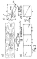
- a diagram is shown in FIG. 2a, in which the x / y path components S x and S y of the particle track 23 are shown.
- the calculation of the third speed component v z is determined indirectly on the basis of the residence time of the particle, for example in the middle light section plane 9.2.
- an additional time structure is imprinted on the particle track, for example by multiple exposure or modulation of the laser radiation. This then gives the time t bE2 shown in the diagram in FIG. 2a, that of the length of time of the particle in the Light section plane 9.2 corresponds.
- the duration of stay t bE2 can also be calculated by forming the ratio of the particle track 23.2 of the middle light section plane 9.2 to the total length of the Teliches track 23.
- the ratio of length of stay t bE2 and exposure time t b corresponds to the ratio of the length S E2z of the particle track 23.2 and the total length of the particle track 23.
- the prerequisite for this is, however, that the track is detected in all three light section planes and the beginning and end in the two outer ones Levels can be found.
- FIG. 3 Another possibility for measuring the z component is shown in FIG. 3.
- a light section plane is asymmetrically intensity-modulated in the z-direction, the light intensity curve being indicated in the diagram shown in FIG. 3c. This is a half Gauss curve.
- intensity values of the particle track 23 can also be used to determine the z component, for example the intensity value when entering the middle light section plane and the intensity value when leaving the middle light section plane.
- a recording system with only one recording device for example a camera or a high-speed camera with high spatial resolution, can be used instead.
Abstract
Description
Die Erfindung betrifft ein Verfahren zum Erfassen 3-dimensionaler Strömungsstrukturen. Darüber hinaus betrifft die Erfindung eine Vorrichtung zum Erfassen 3-dimensionaler Strömungsstrukturen mit einer Lichtquelle zum Erzeugen einer Lichtschnittebene, einer der Lichtschnittebene zugeordneten Aufnahmeeinrichtung zum Erfassen von Streulicht, das ein Teilchen beim Durchqueren der Lichtschnittebene erzeugt, und mit einer Auswerte- und Steuereinrichtung.The invention relates to a method for detecting 3-dimensional flow structures. In addition, the invention relates to a device for detecting 3-dimensional flow structures with a light source for generating a light section plane, a receiving device assigned to the light section plane for detecting scattered light that generates a particle when crossing the light section plane, and with an evaluation and control device.
Aus dem Stand der Technik sind allgemein Strömungsanemometer, beispielsweise Laserdoppleranemometer bekannt, die ein punktuelles Vermessen von Strömungsfeldern erlauben. Aufgrund der lediglich punktuellen Vermessung sind diese Verfahren sehr zeitaufwendig. Zur simultanen Erfassung räumlicher Turbulenzstrukturen sind daher Ganzfeldverfahren unerläßlich.Flow anemometers, for example laser Doppler anemometers, are generally known from the prior art, which allow a selective measurement of flow fields. Due to the fact that the measurements are only punctiform, these methods are very good time consuming. Whole-field methods are therefore indispensable for the simultaneous detection of spatial turbulence structures.
Hier sind bisher lediglich 2-dimensionale Verfahren, wie das Laser-Lichtschnittverfahren mit Echtzeitvektorisierung und die Particle Image Velocimetry (PIV) bekannt. Diese Verfahren erfordern jedoch ein sequentielles Abtasten des Strömungsfeldes, in dem Sinne, daß räumliche Strukturen durch Aneinanderreihen von mehreren, zeitlich aufeinanderfolgend aufzunehmenden Lichtschnittebenen untersucht werden müssen.So far, only 2-dimensional methods such as the laser light section method with real-time vectorization and particle image velocimetry (PIV) are known. However, these methods require a sequential scanning of the flow field, in the sense that spatial structures have to be examined by stringing together several light section planes to be recorded in succession.
Der Nachteil dieser Verfahren liegt darin, daß sie bei vielen technisch relevanten Strömungsproblemen nicht anwendbar sind, insbesondere dann, wenn die Strömung instationär ist und die Geschwindigkeitskomponenten senkrecht zur Lichtschnittebene (Untersuchungsebene) groß sind, und der apparative Aufbau aufgrund mangelnder optischer Möglichkeiten Lichtschnittebenen in Richtung der Hauptströmung nicht zuläßt.The disadvantage of these methods is that they cannot be used for many technically relevant flow problems, especially if the flow is unsteady and the speed components perpendicular to the light section plane (examination plane) are large, and the apparatus structure due to a lack of optical possibilities in the direction of the light section plane Main flow does not allow.
Das Verfahren mit den Merkmalen des Anspruchs 1 beziehungsweise die Vorrichtung mit den Merkmalen des Anspruchs 5 haben demgegenüber den Vorteil, daß auch bisher nicht analysierbare Strömungsfelder 3-dimensional erfaßbar sind. Dies wird insbesondere dadurch erreicht, daß neben einer Lichtschnittebene weitere Lichtschnittebenen unterschiedlicher Wellenlänge parallel und räumlich versetzt zueinander erzeugt werden. Diese Mehrschichtanordnung von Lichtschnittebenen erlaubt die Bestimmung der dritten Geschwindigkeitskomponente, ohne das Strömungsfeld sequentiell abtasten zu müssen.In contrast, the method with the features of
Als besonders vorteilhaft hat sich herausgestellt, wenn das Licht zur Erzeugung der Lichtschnittebenen zeitabhängig intensitätsmoduliert, zum Beispiel mit einer Braggzelle, wird. Diese Intensitätsmodulation findet sich entsprechend auch im Streulicht der bewegten Teilchen (Tracerpartikel) im Strömungsfeld wieder. Dadurch läßt sich eindeutig Anfangs-, Endpunkt und Richtung der Streuteilchen auf der Aufnahme identifizieren (Pfeilkodierung).It has proven to be particularly advantageous if the light for generating the light section planes is intensity-modulated in a time-dependent manner, for example with a Bragg cell. This intensity modulation can also be found in the scattered light of the moving particles (tracer particles) in the flow field. This enables the start, end point and direction of the scattering particles to be clearly identified on the image (arrow coding).
In einer Weiterbildung der Erfindung ist zur Erzeugung der Lichtschnittebenen eine einzige Lichtquelle vorgesehen, die Licht unterschiedlicher Wellenlängen, vorzugsweise Laser, ausstrahlt, wobei ein Farbteiler die Aufteilung des mehrfarbigen Lichts in die einzelnen Wellenlängen vornimmt.In a further development of the invention, a single light source is provided for generating the light section planes, which emits light of different wavelengths, preferably lasers, a color splitter dividing the multicolored light into the individual wavelengths.
In einer weiteren Ausführungsform sind statt der einen Lichtquelle mehrere Lichtquellen, vorzugsweise Laser, vorgesehen, die jeweils eine andere Wellenlänge aufweisen und jeweils eine Lichtschnittebene erzeugen.In a further embodiment, instead of the one light source, a plurality of light sources, preferably lasers, are provided, each having a different wavelength and each generating a light section plane.
Vorzugsweise unifassen die den Lichtschnittebenen zugeordneten Aufnahmevorrichtungen kostengünstige CCD-Arrays, die das aufgenommene Bild einem Rechner zur Weiterverarbeitung zuführen.The recording devices assigned to the light section planes preferably include inexpensive CCD arrays which feed the recorded image to a computer for further processing.
In einer Weiterbildung der Erfindung ist jeder Aufnahmevorrichtung eine Justiereinrichtung zugeordnet, die ein genaues Fokussieren auf die entsprechende Lichtschnittebene erlaubt. Damit läßt sich die Qualität des Meßergebnisses weiter erhöhen.In a further development of the invention, an adjustment device is assigned to each recording device, which permits precise focusing on the corresponding light section plane. This can further increase the quality of the measurement result.
Da vorzugsweise mehrere CCD-Arrays zur Erfassung des in den Lichtschnittebenen erzeugten Streulichts eingesetzt werden, müssen Monochromatoren bzw. Interferenzfilter im Strahlengang der CCD-Arrays vorgeschaltet werden, um Streulicht der nicht zugeordneten Lichtschnittebenen wegzufiltern.Since preferably several CCD arrays are used to detect the scattered light generated in the light section planes, monochromators or interference filters must be connected upstream in the beam path of the CCD arrays in order to filter out scattered light from the unassigned light section planes.
Vorteilhaft ist es darüber hinaus, die Aufnahmevorrichtungen durch eine einzige Farbvideo- oder Farbfotokamera zu ersetzen, die anhand der erfaßten Farbe des Streulichts eine Zuordnung zu der jeweiligen Lichtschnittebene durchführt. Damit ist eine Vereinfachung des Aufbaus möglich.It is also advantageous to replace the recording devices with a single color video or color photo camera, which uses the detected color of the scattered light to carry out an assignment to the respective light section plane. This simplifies the structure.
Eine alternative Möglichkeit besteht im Aufbau eines breiten Lichtschnitts mit kontinuierlicher Farbvariation (in dritter Dimension) und der Erfassung des Streulichts mit einer Farbvideokamera. Durch die Wahl eines geeigneten Objektivs bzw. durch Abblenden ist eine scharfe Abbildung der gesamten Lichtschnittbreite zu erzielen. Als Lichtquelle kann eine intensive Weißlichtquelle oder ein Weißlichtlaser mit nachgeschalteter spektraler Zerlegung (Prisma, Gitter) und Lichtschnittoptik dienen.An alternative option is to set up a wide light section with continuous color variation (in the third dimension) and capture the scattered light with a color video camera. By choosing a suitable lens or by stopping down, a clear image of the entire light section width can be achieved. An intensive white light source or a white light laser with subsequent spectral decomposition (prism, grating) and light section optics can serve as the light source.
Weitere Vorteile und Ausgestaltungen der Erfindung ergeben sich aus den übrigen Unteransprüchen.Further advantages and refinements of the invention result from the remaining subclaims.
Die Erfindung wird nun anhand von Ausführungsbeispielen mit Bezug auf die Zeichnungen näher beschrieben. Dabei zeigen:
- Figuren 1a,b
- eine schematische Darstellung der erfindungsgemäßen Vorrichtung und der von der Vorrichtung erfaßten Bilder;
- Figuren 2a-d
- eine schematische Darstellung der erfindungsgemäßen Vorrichtung zur Erläuterung der Berechnung von Geschwindigkeitskomponenten, und
- Figuren 3a-d
- eine schematische Darstellung eines weiteren Ausführungsbeispiels der Erfindung, sowie der Diagramme zur Erläuterung des Meßverfahrens.
- Figures 1a, b
- a schematic representation of the device according to the invention and the images captured by the device;
- Figures 2a-d
- a schematic representation of the device according to the invention for explaining the calculation of speed components, and
- Figures 3a-d
- is a schematic representation of another embodiment of the invention, and the diagrams for explaining the measurement method.
Eine Meßvorrichtung 1 umfaßt einen Ar-Ionen-Laser 3, der u.a. Licht mit den Wellenlängen 476,5 nm, 488 nm, und 514 nm erzeugt. Das vom Laser erzeugte Licht wird einem Farbteiler 5 zugeführt, der das Licht in die einzelnen Farben beziehungsweise Wellenlängen zerlegt. Die zerlegte Lichtstrahlung wird dann jeweils einer Optik 7.1, 7.2 beziehungsweise 7.3 zugeführt, die sogenannte Lichtschnittebenen 9 erzeugen.A
Bedingt durch die Farbtrennung unterscheiden sich die drei Lichtschnittebenen 9.1, 9.2, 9.3 eindeutig durch ihre Wellenlänge.Due to the color separation, the three light section planes 9.1, 9.2, 9.3 clearly differ in their wavelength.
Den Lichtschnittebenen zugeordnet ist ein Objektiv 11, das von den Lichtschnittebenen 9 kommendes Licht gebündelt einem Strahlteiler 13 zuführt. Der Strahlteiler 13 hat die Aufgabe, das ankommende Licht den drei Aufnahmevorrichtungen 15 zuzuleiten. Eine Fokussierung der einzelnen Aufnahmevorrichtungen auf die jeweilige Schnittebene erfolgt mittels Justiereinrichtungen 17.1, 17.2 und 17.3. Damit läßt sich eine eindeutige Zuordnung einer Aufnahmevorrichtung 15 zu einer Lichtschnittebene 9 erzielen.Associated with the light section planes is an
Im gezeigten Ausführungsbeispiel ist dabei die Aufnahmevorrichtung 15.1 der Lichtschnittebene 9.1, die Aufnahmevorrichtung 15.2 der Lichtschnittebene 9.2 und die Aufnahmevorrichtung 15.3 der Lichtschnittebene 9.3 zugeordnet.In the exemplary embodiment shown, the receiving device 15.1 is assigned to the light section plane 9.1, the receiving device 15.2 to the light section plane 9.2 and the receiving device 15.3 to the light section plane 9.3.
Darüber hinaus ist jeder Aufnahmevorrichtung 15 ein Filter beziehungsweise ein Monochromator 19 vorgeschaltet, der Licht unerwünschter Wellenlänge nicht durchläßt. Im vorliegenden Fall sind die unerwünschten Wellenlängen jene, die die jeweils anderen Aufnahmevorrichtungen aufnehmen.In addition, a filter or a
Die Aufnahme der Lichtstrahlen aus den Lichtschnittebenen erfolgt in den Aufnahmevorrichtungen durch nicht dargestellte CCD-Arrays, die ihre Bildinformationen dann einem nur schematisch gezeigten Rechner 21 zur Auswertung und Weiterverarbeitung, insbesondere zur Digitalisierung und Speicherung zuführen.The light beams from the light section planes are recorded in the recording devices by CCD arrays (not shown), which then transmit their image information to a computer 21, only shown schematically, for evaluation and further processing. in particular for digitization and storage.
Die Funktion der Vorrichtung 1 soll nun anhand der Figuren 1b bis 3 erläutert werden.The function of the
In dem zu analysierenden Strömungsfeld, wie es beispielsweise in Figur 2a dargestellt ist, werden die Lichtschnittebenen 9 parallel zueinander und räumlich versetzt erzeugt, wobei deren Längsachse in Richtung der Hauptströmung zeigt.In the flow field to be analyzed, as shown for example in FIG. 2a, the
Zur Messung des Strömungsfeldes werden nun durch die Strömung mitbewegte Teilchen benutzt, die entweder bereits natürlich vorhanden sind oder aber gezielt zugesetzt werden. Beim Durchqueren einer Lichtschnittebene wird an jedem Teilchen Licht reflektiert, das als Streulicht zum Objektiv 11 gelangt. Solches Streulicht läßt sich vom Zeitpunkt des Eintritts beispielsweise in die Lichtschnittebene 9.1 bis zum Austritt aus der Lichtschnittebene 9.3 durch die drei Aufnahmevorrichtungen 15 erfassen. Die von den CCD-Arrays der Aufnahmevorrichtungen 15 erzeugten Bilder liefern also eine Teilchenspur 23, wie sie beispielhaft in der Figur 1b dargestellt ist. Dabei entspricht die Teilchenspur 23.1 dem Weg in der Lichtschnittebene 9.1, die Teilchenspur 23.2 dem Weg in der Lichtschnittebene 9.2 und die Teilchenspur 23.3 dem Weg in der Lichtschnittebene 9.3. Das zeichnerisch hervorgehobene Ende der Teilchenspur 23.1 und die Pfeilspitze der Teilchenspur 23.3 ergibt sich durch die zeitliche Intensitätsmodulation des Laserlichtes (Pfeilkodierung) und zeigt demnach auch an, ob sich das zu untersuchende Teilchen in der gesamten Belichtungszeit im Bereich der Lichtschnittebenen befunden hat. Das heißt, daß das detektierte Teilchen am Anfang der Belichtungszeit sich am Anfang der Teilchenspur 23.1 befand und am Ende der Belichtungszeit an der Pfeilspitze der Teilchenspur 23.3.For the measurement of the flow field, particles which are also moved by the flow and are either already present naturally or are added specifically are used. When crossing a light section plane, light is reflected on each particle, which reaches the
Diese drei Einzelbilder 25.1, 25.2 und 25.3 setzt der Rechner 9 für die Auswertung zu einem gemeinsamen Bild 27 zusammen. Die sich dann ergebende gesamte Teilchenspur 23 stellt nun ein direktes Abbild des Bewegungsverlaufs des Teilchens in der x-/y-Ebene dar.The
Mit Hilfe der zuvor genannten Belichtungszeit tb und einem Abbildungsmaßstab fa der gesamten Aufnahmeoptik lassen sich die Geschwindigkeitskomponenten in x- und y-Richtung vx und vy berechnen. Zur Verdeutlichung ist in Figur 2a ein Diagramm dargestellt, in dem die x-/y-Wegkomponenten Sx und Sy der Teilchenspur 23 eingezeichnet sind. Anhand dieser Parameter ergeben sich folgende Geschwindigkeitskomponenten:![]()
![]()
Die Berechnung der dritten Geschwindigkeitskomponente vz wird indirekt anhand der Aufenthaltsdauer des Teilchens, beispielsweise in der mittleren Lichtschnittebene 9.2, ermittelt. Hierzu wird der Teilchenspur eine zusätzliche Zeitstruktur, etwa durch Mehrfachbelichtung oder Modulation der Laserstrahlung, aufgeprägt. Daraus ergibt sich dann die in dem Diagramm der Figur 2a gezeigte Zeit tbE2, die der Aufenthaltsdauer des Teilchens in der Lichtschnittebene 9.2 entspricht. Mit Hilfe des in dieser Lichtschnittebene zurückgelegten Weges SE2z in z-Richtung berechnet sich die dritte Geschwindigkeitskomponente zu![]()
![]()
Die Aufenthaltsdauer tbE2 kann darüber hinaus auch durch eine Verhältnisbildung der Teilchenspur 23.2 der mittleren Lichtschnittebene 9.2 zur Gesamtlänge der Telichenspur 23 berechnet werden.The duration of stay t bE2 can also be calculated by forming the ratio of the particle track 23.2 of the middle light section plane 9.2 to the total length of the
So entspricht das Verhältnis von Aufenthaltsdauer tbE2 und Belichtungszeit tb dem Verhältnis der Länge SE2z der Teilchenspur 23.2 und der Gesamtlänge der Teilchenspur 23. Voraussetzung hierfür ist jedoch, daß die Spur in allen drei Lichtschnittebenen nachgewiesen wird und Anfang und Ende in den beiden außenliegenden Ebenen zu finden sind.The ratio of length of stay t bE2 and exposure time t b corresponds to the ratio of the length S E2z of the particle track 23.2 and the total length of the
Eine weitere Möglichkeit zur Vermessung der z-Komponente ist in Figur 3 dargestellt. Hierbei wird eine Lichtschnittebene in z-Richtung asymmetrisch intensitätsmoduliert, wobei der Lichtintensitätsverlauf in dem in Figur 3c dargestellten Diagramm angegeben ist. Es handelt sich hierbei um eine halbe Gauss-Kurve.Another possibility for measuring the z component is shown in FIG. 3. Here, a light section plane is asymmetrically intensity-modulated in the z-direction, the light intensity curve being indicated in the diagram shown in FIG. 3c. This is a half Gauss curve.
Die Aufnahmevorrichtung, im vorliegenden Ausführungsbeispiel eine Videokamera, ist so ausgelegt, daß sie auch unterschiedliche Lichtintensitäten erfassen kann. Anhand der erfaßten Lichtintensität läßt sich auf die z-Position des Teilchens innerhalb der Lichtschnittebene schließen. So läßt sich die durchlaufene Strecke Szmn in z-Richtung anhand der Intensitätsverteilung leicht ermitteln, indem die Intensitätswerte vom Anfangs- und vom Endpunkt der Teilchenspur 23 herangezogen werden. Mit Hilfe dieses Wertes Szmn ergibt sich die Geschwindigkeitskomponente wie folgt:![]()
![]()
Selbstverständlich können zur Ermittlung der z-Komponente auch andere Intensitätswerte der Teilchenspur 23 herangezogen werden, beispielsweise der Intensitätswert beim Eintritt in die mittlere Lichtschnittebene und der Intensitätswert beim Austritt aus der mittleren Lichtschnittebene.Of course, other intensity values of the
Neben der im Ausführungsbeispiel gezeigten Aufnahmeoptik, die drei Aufnahmevorrichtungen umfaßt, kann stattdessen ein Aufnahmesystem mit nur einer Aufnahmevorrichtung, beispielsweise einer Kamera beziehungsweise einer Hochgeschwindigkeitskamera mit hoher Ortsauflösung, verwendet werden.In addition to the recording optics shown in the exemplary embodiment, which comprises three recording devices, a recording system with only one recording device, for example a camera or a high-speed camera with high spatial resolution, can be used instead.
Claims (14)
gekennzeichnet durch
marked by
Applications Claiming Priority (2)
| Application Number | Priority Date | Filing Date | Title |
|---|---|---|---|
| DE19635985 | 1996-09-05 | ||
| DE19635985 | 1996-09-05 |
Publications (2)
| Publication Number | Publication Date |
|---|---|
| EP0829726A1 true EP0829726A1 (en) | 1998-03-18 |
| EP0829726B1 EP0829726B1 (en) | 2003-04-16 |
Family
ID=7804671
Family Applications (1)
| Application Number | Title | Priority Date | Filing Date |
|---|---|---|---|
| EP97111404A Expired - Lifetime EP0829726B1 (en) | 1996-09-05 | 1997-07-05 | Method and apparatus for determining three dimensional flow structures |
Country Status (5)
| Country | Link |
|---|---|
| US (1) | US5883707A (en) |
| EP (1) | EP0829726B1 (en) |
| JP (1) | JPH1090294A (en) |
| DE (2) | DE59709832D1 (en) |
| ES (1) | ES2197267T3 (en) |
Cited By (1)
| Publication number | Priority date | Publication date | Assignee | Title |
|---|---|---|---|---|
| ES2155331A1 (en) * | 1998-05-13 | 2001-05-01 | Univ Madrid Carlos Iii | Velocimetry procedure by particle image correlation with spatial resolution that is less than the size of the query window |
Families Citing this family (27)
| Publication number | Priority date | Publication date | Assignee | Title |
|---|---|---|---|---|
| DE19926494C2 (en) * | 1999-06-10 | 2001-07-26 | Max Planck Gesellschaft | Method and device for imaging microscopic particles |
| DE19928698A1 (en) * | 1999-06-23 | 2000-09-21 | Deutsch Zentr Luft & Raumfahrt | Particle image velocimetry (PIV) measurement device, has light source illuminating slit and camera for taking successive images of particles in motion |
| DE19963393C1 (en) * | 1999-12-28 | 2001-07-26 | Bosch Gmbh Robert | Flow analysis method and apparatus |
| DE10018305C2 (en) | 2000-04-13 | 2002-02-14 | Bosch Gmbh Robert | Flow analysis method and apparatus |
| GB0010123D0 (en) * | 2000-04-27 | 2000-06-14 | Univ Nottingham | Planar light sheet anemometers |
| TW466346B (en) * | 2001-03-05 | 2001-12-01 | Nat Science Council | A low-cost continuous-wave-laser (CW laser) digital particle image velocimetry |
| US6542226B1 (en) | 2001-06-04 | 2003-04-01 | The United States Of America As Represented By The Administrator Of The National Aeronautics And Space Administration | Planar particle imaging and doppler velocimetry system and method |
| DE10312696B3 (en) * | 2003-03-21 | 2004-12-23 | Lavision Gmbh | Procedure for determining the mapping equation for self-calibration in relation to the implementation of stereo PIV procedures |
| DE10343160B3 (en) | 2003-09-18 | 2005-05-25 | Lavision Gmbh | Method for determining a three-dimensional velocity field in a volume |
| DE102004057718B4 (en) * | 2004-11-26 | 2006-08-03 | Iav Gmbh Ingenieurgesellschaft Auto Und Verkehr | Device for the analysis of flow process in the hollow piston of internal combustion engine has laser light cut with axis of cylinder and camera is aligned with of hollow piston opening |
| GB2422193B (en) * | 2004-12-24 | 2008-07-16 | Campbell Scient Ltd | A weather measurement device for determining the speed in a first direction of hydrometeors |
| IL167932A (en) * | 2005-04-10 | 2012-03-29 | Israel Aerospace Ind Ltd | Systems and methods for detecting the position of an object passing through optical screens |
| DE102005056409B3 (en) * | 2005-11-26 | 2007-03-22 | Lavision Gmbh | Method of determining the velocity field in moving gaseous or fluid medium using particles disposed in the medium |
| US7772579B2 (en) * | 2006-05-18 | 2010-08-10 | Massachusetts Institute Of Technology | Method and apparatus for simultaneously measuring a three dimensional position of a particle in a flow |
| WO2007136818A2 (en) * | 2006-05-18 | 2007-11-29 | Massachusetts Institute Of Technology | Method and apparatus for simultaneously measuring a three dimensional postion of a particle in a flow |
| WO2008010870A2 (en) * | 2006-05-18 | 2008-01-24 | Massachusetts Institute Of Technology | Method and apparatus for measuring a position of a particle in a flow |
| DE102006055746A1 (en) * | 2006-11-25 | 2008-05-29 | Lavision Gmbh | Method for correcting a volume mapping equation for determining a velocity field of particles in a volume |
| US7920261B2 (en) | 2008-02-11 | 2011-04-05 | Massachusetts Institute Of Technology | Method and apparatus for detecting and discriminating particles in a fluid |
| TWI404894B (en) * | 2009-12-22 | 2013-08-11 | Ind Tech Res Inst | Illumination system |
| JP5810790B2 (en) * | 2011-09-20 | 2015-11-11 | 富士通株式会社 | Visualization processing program, visualization processing method, and visualization processing apparatus |
| CN103197095B (en) * | 2013-04-08 | 2015-08-12 | 天津大学 | Hierarchical synchronization three dimensional particles image speed measurement method and apparatus |
| CN103604945A (en) * | 2013-10-25 | 2014-02-26 | 河海大学 | Three-channel CMOS synchronous polarization imaging system |
| RU2665344C2 (en) * | 2014-07-08 | 2018-08-29 | Ист Чайна Юниверсити Оф Сайенс Энд Текнолоджи | Method and device of synchronous high-speed photographic rotation of microparticle in hydrocyclone field |
| CN105974596B (en) * | 2016-04-26 | 2018-07-31 | 南京理工大学 | Chromatograph the 3 D stereo means of illumination of particle image velocimetry |
| US10782311B2 (en) * | 2017-02-28 | 2020-09-22 | King Abdullah University Of Science And Technology | Rainbow particle imaging velocimetry for dense 3D fluid velocity imaging |
| US10186051B2 (en) | 2017-05-11 | 2019-01-22 | Dantec Dynamics A/S | Method and system for calibrating a velocimetry system |
| EP3683040A1 (en) * | 2017-07-21 | 2020-07-22 | CL Schutzrechtsverwaltungs GmbH | Optical determining device for an apparatus for additively manufacturing three-dimensional objects |
Citations (3)
| Publication number | Priority date | Publication date | Assignee | Title |
|---|---|---|---|---|
| FR2582403A1 (en) * | 1985-05-24 | 1986-11-28 | Saint Louis Inst Franco Allem | METHOD FOR THE SIMULTANEOUS MEASUREMENT OF THREE SPEED COMPONENTS BY DOPPLER EFFECT LASER ANEMOMETRY METHODS |
| DE4408072A1 (en) * | 1994-02-01 | 1995-08-03 | Deutsche Forsch Luft Raumfahrt | Applying high-speed electronic photography for measurement of flow velocity |
| US5491642A (en) * | 1993-12-03 | 1996-02-13 | United Technologies Corporation | CCD based particle image direction and zero velocity resolver |
Family Cites Families (16)
| Publication number | Priority date | Publication date | Assignee | Title |
|---|---|---|---|---|
| DE2810388A1 (en) * | 1977-03-14 | 1978-09-21 | Bindicator Co | DEVICE FOR OPTICAL MEASUREMENT OF A PRESELECTED PROPERTY OF A SUBSTANCE FLOWING IN A LINE |
| US4429995A (en) * | 1980-07-21 | 1984-02-07 | National Research Development Corporation | Two dimensinal flow analyzer |
| US4661913A (en) * | 1984-09-11 | 1987-04-28 | Becton, Dickinson And Company | Apparatus and method for the detection and classification of articles using flow cytometry techniques |
| DE3544347C1 (en) * | 1985-12-14 | 1987-06-04 | Deutsche Forsch Luft Raumfahrt | Method and device for rapid serial, and thus quasi-instantaneous punctiform measurement of local velocity components of a velocity field |
| US4919536A (en) * | 1988-06-06 | 1990-04-24 | Northrop Corporation | System for measuring velocity field of fluid flow utilizing a laser-doppler spectral image converter |
| US4989969A (en) * | 1988-06-30 | 1991-02-05 | Hughes Danbury Optical Systems, Inc. | Time of flight velocimeter |
| DE4118716A1 (en) * | 1990-07-16 | 1992-01-23 | Gerhart Schroff | METHOD AND ARRANGEMENT FOR THE OPTICAL DETECTION AND EVALUATION OF SPREADING LIGHT SIGNALS |
| SE468925B (en) * | 1991-08-22 | 1993-04-19 | Gert Nilsson | A METHOD AND APPARATUS SHOULD REDUCE THE DISTANCE-BASED FACTOR IN Saturation of STRAIGHT MOVEMENTS WITH AN IMAGING LASER-DOUBLE TECHNIQUE, SPECIFICALLY IN SEATING BLOOD PERFUSION THROUGH |
| DE4200309A1 (en) * | 1992-01-09 | 1993-07-15 | Gerhard Arnold Dr Seiler | Measuring flow of flowing medium within defined measurement vol. - deriving speed of motion of objects in flow from electro=optically acquired electronic image signals |
| DE4237440C1 (en) * | 1992-11-06 | 1994-03-10 | Deutsche Forsch Luft Raumfahrt | Optical imaging system for three=dimensional flow determination - has light source for short time exposure, and stereoscopic video imaging unit with synchronous image shifting by two mirrors which rotate about common axis parallel to line joining entrance-aperture objective lenses |
| DE4313682C2 (en) * | 1993-04-22 | 1996-06-13 | Wolfgang Dipl Ing Frey | Process for the visual determination and measurement of the outflow of slowly flowing liquids with a free mirror using air bubbles as the measuring medium and an arrangement for carrying out the process |
| DE4426956C2 (en) * | 1994-07-29 | 1996-12-05 | Deutsche Forsch Luft Raumfahrt | Method for determining the speed of a flow |
| FR2725034B1 (en) * | 1994-09-22 | 1997-01-03 | Sextant Avionique | TRANSMISSION-RECEPTION HEAD FOR LONGITUDINAL DOPPLER ANEMOMETER |
| US5561515A (en) * | 1994-10-07 | 1996-10-01 | Tsi Incorporated | Apparatus for measuring particle sizes and velocities |
| DE4443069C2 (en) * | 1994-12-03 | 1997-01-16 | Deutsche Forsch Luft Raumfahrt | Method for measuring flow vectors in gas flows |
| DE29601159U1 (en) * | 1996-01-24 | 1996-05-02 | Faerber Adolf | Device for contactless monitoring of the throughput of a flowing material |
-
1997
- 1997-07-05 ES ES97111404T patent/ES2197267T3/en not_active Expired - Lifetime
- 1997-07-05 DE DE59709832T patent/DE59709832D1/en not_active Expired - Fee Related
- 1997-07-05 EP EP97111404A patent/EP0829726B1/en not_active Expired - Lifetime
- 1997-08-30 DE DE19737933A patent/DE19737933A1/en not_active Withdrawn
- 1997-09-04 JP JP9239218A patent/JPH1090294A/en active Pending
- 1997-09-05 US US08/924,804 patent/US5883707A/en not_active Expired - Fee Related
Patent Citations (3)
| Publication number | Priority date | Publication date | Assignee | Title |
|---|---|---|---|---|
| FR2582403A1 (en) * | 1985-05-24 | 1986-11-28 | Saint Louis Inst Franco Allem | METHOD FOR THE SIMULTANEOUS MEASUREMENT OF THREE SPEED COMPONENTS BY DOPPLER EFFECT LASER ANEMOMETRY METHODS |
| US5491642A (en) * | 1993-12-03 | 1996-02-13 | United Technologies Corporation | CCD based particle image direction and zero velocity resolver |
| DE4408072A1 (en) * | 1994-02-01 | 1995-08-03 | Deutsche Forsch Luft Raumfahrt | Applying high-speed electronic photography for measurement of flow velocity |
Cited By (1)
| Publication number | Priority date | Publication date | Assignee | Title |
|---|---|---|---|---|
| ES2155331A1 (en) * | 1998-05-13 | 2001-05-01 | Univ Madrid Carlos Iii | Velocimetry procedure by particle image correlation with spatial resolution that is less than the size of the query window |
Also Published As
| Publication number | Publication date |
|---|---|
| US5883707A (en) | 1999-03-16 |
| DE19737933A1 (en) | 1998-03-12 |
| ES2197267T3 (en) | 2004-01-01 |
| DE59709832D1 (en) | 2003-05-22 |
| EP0829726B1 (en) | 2003-04-16 |
| JPH1090294A (en) | 1998-04-10 |
Similar Documents
| Publication | Publication Date | Title |
|---|---|---|
| EP0829726B1 (en) | Method and apparatus for determining three dimensional flow structures | |
| EP0419936B1 (en) | Process and apparatus for the phase indication of radiation, especially light radiation | |
| EP0898783B1 (en) | Scanning microscope in which a sample is simultaneously and optically excited at various points | |
| DE112015000627B4 (en) | Microspectroscopic device | |
| DE19912500A1 (en) | Apparatus to monitor characteristics at a running paper web has optic fibers aligned at lateral line of measurement points to register infra red light waves to be converted into pixels at a detector for computer processing | |
| DE102010049672B3 (en) | Laser Doppler line distance sensor for three-dimensional shape measurement of moving solids | |
| DE102006015170B4 (en) | Method and arrangement for generating an enlarged measurement volume for determining the structure and / or winding speed of textile fibers on the basis of laser Doppler anemometry | |
| EP0307668B1 (en) | Method and apparatus for measuring the speed of flow in wind tunnels | |
| DE3503086C1 (en) | Method and device for measuring the wall thickness of transparent objects | |
| EP3811025B1 (en) | Device for chromatic confocal optical measurement and confocal imaging of a measurement object, and method | |
| DE60036467T2 (en) | METHOD AND DEVICE FOR DOPPLER SPEED MEASUREMENT | |
| EP1181561B1 (en) | Method and device for flow analysis | |
| EP1542051B1 (en) | Apparatus and method for wavelength separation in a scanning microscope | |
| CH629603A5 (en) | IMAGE TRANSFER DEVICE FOR EXAMINING INAccessible LOTS OF AN OBJECT. | |
| DE3116671A1 (en) | INSTRUMENT FOR AUTOMATICALLY DETERMINING THE CHARACTERISTICS OF AN OPTICAL SYSTEM | |
| DE10056329B4 (en) | Optical distance measuring method and distance sensor | |
| DE3712153C1 (en) | Process for the measurement of flow vectors in gas flows | |
| CH628425A5 (en) | METHOD AND DEVICE FOR CONTACTLESS MEASUREMENT OF LINEAR DISTANCES, ESPECIALLY THE DIAMETER. | |
| DE102011015478B4 (en) | Apparatus and method for detecting and analyzing laser radiation | |
| CH697319B1 (en) | Method and apparatus for geometric calibration of optoelectronic measuring cameras. | |
| DE4027328B4 (en) | 3D camera for the detection of surface structures, in particular for dental purposes | |
| DE3106025C2 (en) | Method and device for the rapid measurement of local speed components in a speed field | |
| DE102019001498A1 (en) | Device for optical measurement and mapping of a measurement object and method | |
| DE202019103527U1 (en) | Optical measuring device with confocal-chromatic, optical sensor | |
| DE102007063355B4 (en) | Method for the optical measurement of velocities according to the spatial frequency filter method and sensor for the optical measurement of velocities |
Legal Events
| Date | Code | Title | Description |
|---|---|---|---|
| PUAI | Public reference made under article 153(3) epc to a published international application that has entered the european phase |
Free format text: ORIGINAL CODE: 0009012 |
|
| AK | Designated contracting states |
Kind code of ref document: A1 Designated state(s): CH DE ES FR GB IT LI SE |
|
| 17P | Request for examination filed |
Effective date: 19980918 |
|
| AKX | Designation fees paid |
Free format text: CH DE ES FR GB IT LI SE |
|
| RBV | Designated contracting states (corrected) |
Designated state(s): CH DE ES FR GB IT LI SE |
|
| 17Q | First examination report despatched |
Effective date: 20011213 |
|
| GRAG | Despatch of communication of intention to grant |
Free format text: ORIGINAL CODE: EPIDOS AGRA |
|
| GRAG | Despatch of communication of intention to grant |
Free format text: ORIGINAL CODE: EPIDOS AGRA |
|
| GRAH | Despatch of communication of intention to grant a patent |
Free format text: ORIGINAL CODE: EPIDOS IGRA |
|
| GRAH | Despatch of communication of intention to grant a patent |
Free format text: ORIGINAL CODE: EPIDOS IGRA |
|
| GRAA | (expected) grant |
Free format text: ORIGINAL CODE: 0009210 |
|
| AK | Designated contracting states |
Designated state(s): CH DE ES FR GB IT LI SE |
|
| REG | Reference to a national code |
Ref country code: GB Ref legal event code: FG4D Free format text: NOT ENGLISH |
|
| REG | Reference to a national code |
Ref country code: CH Ref legal event code: EP |
|
| REF | Corresponds to: |
Ref document number: 59709832 Country of ref document: DE Date of ref document: 20030522 Kind code of ref document: P |
|
| PG25 | Lapsed in a contracting state [announced via postgrant information from national office to epo] |
Ref country code: SE Free format text: LAPSE BECAUSE OF FAILURE TO SUBMIT A TRANSLATION OF THE DESCRIPTION OR TO PAY THE FEE WITHIN THE PRESCRIBED TIME-LIMIT Effective date: 20030716 |
|
| PG25 | Lapsed in a contracting state [announced via postgrant information from national office to epo] |
Ref country code: LI Free format text: LAPSE BECAUSE OF NON-PAYMENT OF DUE FEES Effective date: 20030731 Ref country code: CH Free format text: LAPSE BECAUSE OF NON-PAYMENT OF DUE FEES Effective date: 20030731 |
|
| GBT | Gb: translation of ep patent filed (gb section 77(6)(a)/1977) | ||
| REG | Reference to a national code |
Ref country code: ES Ref legal event code: FG2A Ref document number: 2197267 Country of ref document: ES Kind code of ref document: T3 |
|
| ET | Fr: translation filed | ||
| PLBE | No opposition filed within time limit |
Free format text: ORIGINAL CODE: 0009261 |
|
| STAA | Information on the status of an ep patent application or granted ep patent |
Free format text: STATUS: NO OPPOSITION FILED WITHIN TIME LIMIT |
|
| REG | Reference to a national code |
Ref country code: CH Ref legal event code: PL |
|
| 26N | No opposition filed |
Effective date: 20040119 |
|
| PGFP | Annual fee paid to national office [announced via postgrant information from national office to epo] |
Ref country code: DE Payment date: 20050916 Year of fee payment: 9 |
|
| PGFP | Annual fee paid to national office [announced via postgrant information from national office to epo] |
Ref country code: FR Payment date: 20060719 Year of fee payment: 10 |
|
| PGFP | Annual fee paid to national office [announced via postgrant information from national office to epo] |
Ref country code: GB Payment date: 20060721 Year of fee payment: 10 |
|
| PGFP | Annual fee paid to national office [announced via postgrant information from national office to epo] |
Ref country code: ES Payment date: 20060724 Year of fee payment: 10 |
|
| PGFP | Annual fee paid to national office [announced via postgrant information from national office to epo] |
Ref country code: IT Payment date: 20060731 Year of fee payment: 10 |
|
| PG25 | Lapsed in a contracting state [announced via postgrant information from national office to epo] |
Ref country code: DE Free format text: LAPSE BECAUSE OF NON-PAYMENT OF DUE FEES Effective date: 20070201 |
|
| GBPC | Gb: european patent ceased through non-payment of renewal fee |
Effective date: 20070705 |
|
| PG25 | Lapsed in a contracting state [announced via postgrant information from national office to epo] |
Ref country code: GB Free format text: LAPSE BECAUSE OF NON-PAYMENT OF DUE FEES Effective date: 20070705 |
|
| REG | Reference to a national code |
Ref country code: FR Ref legal event code: ST Effective date: 20080331 |
|
| PG25 | Lapsed in a contracting state [announced via postgrant information from national office to epo] |
Ref country code: FR Free format text: LAPSE BECAUSE OF NON-PAYMENT OF DUE FEES Effective date: 20070731 |
|
| REG | Reference to a national code |
Ref country code: ES Ref legal event code: FD2A Effective date: 20070706 |
|
| PG25 | Lapsed in a contracting state [announced via postgrant information from national office to epo] |
Ref country code: ES Free format text: LAPSE BECAUSE OF NON-PAYMENT OF DUE FEES Effective date: 20070706 |
|
| PG25 | Lapsed in a contracting state [announced via postgrant information from national office to epo] |
Ref country code: IT Free format text: LAPSE BECAUSE OF NON-PAYMENT OF DUE FEES Effective date: 20070705 |