EP0829595A2 - Edging strip - Google Patents
Edging strip Download PDFInfo
- Publication number
- EP0829595A2 EP0829595A2 EP97307235A EP97307235A EP0829595A2 EP 0829595 A2 EP0829595 A2 EP 0829595A2 EP 97307235 A EP97307235 A EP 97307235A EP 97307235 A EP97307235 A EP 97307235A EP 0829595 A2 EP0829595 A2 EP 0829595A2
- Authority
- EP
- European Patent Office
- Prior art keywords
- edging strip
- strip according
- formation
- rearwardly extending
- plate member
- Prior art date
- Legal status (The legal status is an assumption and is not a legal conclusion. Google has not performed a legal analysis and makes no representation as to the accuracy of the status listed.)
- Withdrawn
Links
- 238000007688 edging Methods 0.000 title claims 17
- 230000015572 biosynthetic process Effects 0.000 claims abstract description 30
- 239000000463 material Substances 0.000 claims abstract description 7
- 238000005755 formation reaction Methods 0.000 claims description 28
- 238000005452 bending Methods 0.000 claims description 3
- 239000004820 Pressure-sensitive adhesive Substances 0.000 claims description 2
- 238000003780 insertion Methods 0.000 claims description 2
- 230000037431 insertion Effects 0.000 claims description 2
- 238000000926 separation method Methods 0.000 claims description 2
- 229910003460 diamond Inorganic materials 0.000 abstract 1
- 239000010432 diamond Substances 0.000 abstract 1
- OSGAYBCDTDRGGQ-UHFFFAOYSA-L calcium sulfate Inorganic materials [Ca+2].[O-]S([O-])(=O)=O OSGAYBCDTDRGGQ-UHFFFAOYSA-L 0.000 description 2
- ZOMBKNNSYQHRCA-UHFFFAOYSA-J calcium sulfate hemihydrate Chemical compound O.[Ca+2].[Ca+2].[O-]S([O-])(=O)=O.[O-]S([O-])(=O)=O ZOMBKNNSYQHRCA-UHFFFAOYSA-J 0.000 description 2
- 239000011507 gypsum plaster Substances 0.000 description 2
- 238000000034 method Methods 0.000 description 2
- 239000002991 molded plastic Substances 0.000 description 1
- 238000000465 moulding Methods 0.000 description 1
- 238000010422 painting Methods 0.000 description 1
- 239000002023 wood Substances 0.000 description 1
Images


Classifications
-
- F—MECHANICAL ENGINEERING; LIGHTING; HEATING; WEAPONS; BLASTING
- F16—ENGINEERING ELEMENTS AND UNITS; GENERAL MEASURES FOR PRODUCING AND MAINTAINING EFFECTIVE FUNCTIONING OF MACHINES OR INSTALLATIONS; THERMAL INSULATION IN GENERAL
- F16B—DEVICES FOR FASTENING OR SECURING CONSTRUCTIONAL ELEMENTS OR MACHINE PARTS TOGETHER, e.g. NAILS, BOLTS, CIRCLIPS, CLAMPS, CLIPS OR WEDGES; JOINTS OR JOINTING
- F16B5/00—Joining sheets or plates, e.g. panels, to one another or to strips or bars parallel to them
- F16B5/12—Fastening strips or bars to sheets or plates, e.g. rubber strips, decorative strips for motor vehicles, by means of clips
- F16B5/126—Fastening strips or bars to sheets or plates, e.g. rubber strips, decorative strips for motor vehicles, by means of clips at least one of the sheets, plates, bars or strips having integrally formed or integrally connected snap-in-features
-
- E—FIXED CONSTRUCTIONS
- E04—BUILDING
- E04F—FINISHING WORK ON BUILDINGS, e.g. STAIRS, FLOORS
- E04F19/00—Other details of constructional parts for finishing work on buildings
- E04F19/02—Borders; Finishing strips, e.g. beadings; Light coves
- E04F19/04—Borders; Finishing strips, e.g. beadings; Light coves for use between floor or ceiling and wall, e.g. skirtings
- E04F19/0436—Borders; Finishing strips, e.g. beadings; Light coves for use between floor or ceiling and wall, e.g. skirtings between ceiling and wall
-
- E—FIXED CONSTRUCTIONS
- E04—BUILDING
- E04F—FINISHING WORK ON BUILDINGS, e.g. STAIRS, FLOORS
- E04F19/00—Other details of constructional parts for finishing work on buildings
- E04F19/02—Borders; Finishing strips, e.g. beadings; Light coves
- E04F19/04—Borders; Finishing strips, e.g. beadings; Light coves for use between floor or ceiling and wall, e.g. skirtings
- E04F19/0459—Borders; Finishing strips, e.g. beadings; Light coves for use between floor or ceiling and wall, e.g. skirtings characterised by the fixing method
- E04F19/0463—Plinths fixed by snap-action in a direction perpendicular to the wall
-
- E—FIXED CONSTRUCTIONS
- E04—BUILDING
- E04F—FINISHING WORK ON BUILDINGS, e.g. STAIRS, FLOORS
- E04F19/00—Other details of constructional parts for finishing work on buildings
- E04F19/02—Borders; Finishing strips, e.g. beadings; Light coves
- E04F19/04—Borders; Finishing strips, e.g. beadings; Light coves for use between floor or ceiling and wall, e.g. skirtings
- E04F19/0459—Borders; Finishing strips, e.g. beadings; Light coves for use between floor or ceiling and wall, e.g. skirtings characterised by the fixing method
- E04F19/0477—Plinths fixed by means of adhesive
-
- E—FIXED CONSTRUCTIONS
- E04—BUILDING
- E04F—FINISHING WORK ON BUILDINGS, e.g. STAIRS, FLOORS
- E04F19/00—Other details of constructional parts for finishing work on buildings
- E04F19/02—Borders; Finishing strips, e.g. beadings; Light coves
- E04F19/04—Borders; Finishing strips, e.g. beadings; Light coves for use between floor or ceiling and wall, e.g. skirtings
- E04F2019/0404—Borders; Finishing strips, e.g. beadings; Light coves for use between floor or ceiling and wall, e.g. skirtings characterised by the material
- E04F2019/0413—Borders; Finishing strips, e.g. beadings; Light coves for use between floor or ceiling and wall, e.g. skirtings characterised by the material of metal
-
- E—FIXED CONSTRUCTIONS
- E04—BUILDING
- E04F—FINISHING WORK ON BUILDINGS, e.g. STAIRS, FLOORS
- E04F19/00—Other details of constructional parts for finishing work on buildings
- E04F19/02—Borders; Finishing strips, e.g. beadings; Light coves
- E04F19/04—Borders; Finishing strips, e.g. beadings; Light coves for use between floor or ceiling and wall, e.g. skirtings
- E04F2019/0404—Borders; Finishing strips, e.g. beadings; Light coves for use between floor or ceiling and wall, e.g. skirtings characterised by the material
- E04F2019/0422—Borders; Finishing strips, e.g. beadings; Light coves for use between floor or ceiling and wall, e.g. skirtings characterised by the material of organic plastics with or without reinforcements or filling materials
- E04F2019/0427—Borders; Finishing strips, e.g. beadings; Light coves for use between floor or ceiling and wall, e.g. skirtings characterised by the material of organic plastics with or without reinforcements or filling materials with a integrally formed hinge
Definitions
- This invention relates to skirting, cornices, dado rails and also for picture frames.
- skirting or the like comprises a rear plate member adapted to be attached to a wall, the plate member being in hinged association with a shaped front portion including a rearwardly extending formation adapted to engage a complemental formation on the plate member.
- the front portion also includes at a low level, a formation which abuts the floor for example if the invention is applied to skirting.
- the invention preferably comprises a suitable polymeric material.
- the rearwardly extending formation preferably includes one or more hooked or barbed formations and is insertable into a complemental formation on the plate member comprising a channel.
- the channel may also include formations preventing removal of the inserted barbed formation.
- both the rearwardly extending formation and the channel may include interengaging barbs on either side thereof. In the preferred form, only one side of each is barbed. This permits removal of the rearwardly extending formation by bending the opposite wall of the channel. This permits transport of the skirting in a closed form.
- the depth of insertion of the barbed formation into the channel defines a separation distance between the front and rear portions, permitting introducing of electrical cabling or the like if desired.
- the front and rear portions are integral and the hinged association comprises a longitudinal line of reduced thickness, the inherent flexibility of the polymeric material permitting the required degree of bending.
- a reinforced section may be provided adjacent the line of reduced thickness.
- the hinge is located at the top of the rear plate while in an alternative form the rear plate includes a flange at the top end thereof, the flange being in hinged association with the front portion.
- a short rearwardly extending flange may also be provided in either form of the invention to ensure a perfect fit against the wall when the rear plate is secured thereto.
- the skirting of the invention finds equal application as a cornice or dado rail, and is very easy to assemble.
- the plate member may be provided with double sided pressure sensitive adhesive tape to facilitate positioning.
- the skirting is then fastened more permanently by nails, screws or the like which are simply hammered or otherwise forced through the rear plate into the wall.
- the skirting of the invention may be manufactured in different sizes and shapes and in particular, a reduced size may be manufactured for use as an easy to assemble picture frame.
- the invention could be simply attached as described above to a backing material of a picture, photograph or painting.
- the front portion is concavely arcuate and this time a formation is provided which abuts the ceiling.
- the hinged association may be as is described above, but in this case is between a flange at the base of the rear plate and the front portion.
- a short rearwardly extending flange to ensure flush fitting against the wall is also provided.
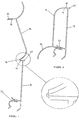
- skirting comprises a rear plate 10 which is attachable to wall 12 and a shaped front portion 14.
- the skirting comprises a polymeric material and includes an integral hinged section between the front and rear portion which consists of a longitudinal line of reduced thickness 16 as shown in the magnified area of Figure 1.
- FIG. 3 An alternative form of hinge is illustrated in Figure 3. This form includes a reinforced section 30 adjacent to the line of reduced thickness.
- the front portion 14 has a rearwardly extending protrusion 18 which includes barbs 20.
- the front portion 14 is swung down so that the barbed protrusion engages a channelled formation 22 integral with the rear plate. The barbs prevent removal of the protrusion.
- FIG. 4 An alternative form of barbed protrusion is illustrated in Figure 4. This form does permit opening before the skirting is fixed to the wall and facilitates transportation in a closed form.
- the front portion 14 includes a shaped formation 24 which extends to abut the floor 26.
- FIG. 5 an alternative embodiment is shown in which the rear plate has a flange 40 at the top end thereof and the hinge 16 in the form of a line of reduced thickness) is located between the flange and the front portion 14. Furthermore a short rearwardly extending flange 42 is also provided. This permits a flush fitting of the skirting against the wall.
- flanges 40 and 42 are provided with a hinge Iccated at 16.
- the cornice opens and closes as described above with barbs 20 at the end of protrusion 18 engaging the channelled formation 22.
Abstract
Description
Claims (16)
- An edging strip comprising a rear plate member adapted to be attached to a wall, the plate member being in hinged association with a shaped front portion including a rearwardly extending formation adapted to engage a complemental formation on the plate member.
- Edging strip according to claim 1 in which the front portion also includes at a low level, a formation which abuts the floor for example if the invention is applied to skirting.
- Edging strip according to claim 1 in which the rearwardly extending formation includes one or more hooked or barbed formations and is insertable into a complemental formation on the plate member comprising a channel.
- Edging strip according to claim 3 in which the channel includes formations preventing removal of the inserted barbed formation.
- Edging strip according to claim 4 in which both the rearwardly extending formation and the channel may include interengaging barbs on either side thereof.
- Edging strip according to claim 4 in which the rearwardly extending formation and the channel include barbs on only one side thereof.
- Edging strip according to claim 3 in which the depth of insertion of the barbed formation into the channel defines a separation distance between the front and rear portions, permitting introducing of electrical cabling or the like.
- Edging strip according to any of the above claims in which the front and rear portions are integral and the hinged association comprises a longitudinal line of reduced thickness, the inherent flexibility of the polymeric material permitting the required degree of bending.
- Edging strip according to claim 8 in which a reinforced section is proved adjacent to the line of reduced thickness.
- Edging strip according to any of the above claims in which the hinged association is located at the top of the rear plate.
- Edging strip according to claims 1 to 9 in which the rear plate includes a flange at the top end thereof, the flange being in hinged association with the front portion.
- Edging strip according to any of the above claims in which a short rearwardly extending flange may also be provided in either form of the invention to ensure a perfect fit against the wall when the rear plate is secured thereto.
- Edging strip according to any of the above claims, except claim 2, which finds particular application as a cornice, in which the front portion is concavely arcuate and this time a formation is provided which abuts the ceiling.
- Edging strip according to any of the above claims comprises a suitable polymeric material.
- Edging strip according to any of the above claims in which the plate member is provided with double-sided pressure sensitive adhesive tape to facilitate positioning.
- Edging strip according to any of the above claims being one of a skirting, cornice or dado rail.
Applications Claiming Priority (2)
| Application Number | Priority Date | Filing Date | Title |
|---|---|---|---|
| ZA967786 | 1996-09-16 | ||
| ZA9607786 | 1996-09-16 |
Publications (2)
| Publication Number | Publication Date |
|---|---|
| EP0829595A2 true EP0829595A2 (en) | 1998-03-18 |
| EP0829595A3 EP0829595A3 (en) | 1999-10-13 |
Family
ID=25585889
Family Applications (1)
| Application Number | Title | Priority Date | Filing Date |
|---|---|---|---|
| EP97307235A Withdrawn EP0829595A3 (en) | 1996-09-16 | 1997-09-16 | Edging strip |
Country Status (2)
| Country | Link |
|---|---|
| EP (1) | EP0829595A3 (en) |
| AU (1) | AU3680397A (en) |
Cited By (1)
| Publication number | Priority date | Publication date | Assignee | Title |
|---|---|---|---|---|
| EP2090717A1 (en) | 2008-02-18 | 2009-08-19 | Natural Faber, S.L. | Base element with a covering lid and method for installing said element on wall coverings |
Citations (3)
| Publication number | Priority date | Publication date | Assignee | Title |
|---|---|---|---|---|
| FR2107470A5 (en) * | 1970-09-11 | 1972-05-05 | Ind Onderneming | |
| GB1512288A (en) * | 1976-05-12 | 1978-06-01 | Potter J | Corner fillets |
| EP0477721A2 (en) * | 1990-09-23 | 1992-04-01 | Nmc S.A. | Suspended coffered ceiling |
-
1997
- 1997-09-03 AU AU36803/97A patent/AU3680397A/en not_active Abandoned
- 1997-09-16 EP EP97307235A patent/EP0829595A3/en not_active Withdrawn
Patent Citations (3)
| Publication number | Priority date | Publication date | Assignee | Title |
|---|---|---|---|---|
| FR2107470A5 (en) * | 1970-09-11 | 1972-05-05 | Ind Onderneming | |
| GB1512288A (en) * | 1976-05-12 | 1978-06-01 | Potter J | Corner fillets |
| EP0477721A2 (en) * | 1990-09-23 | 1992-04-01 | Nmc S.A. | Suspended coffered ceiling |
Cited By (1)
| Publication number | Priority date | Publication date | Assignee | Title |
|---|---|---|---|---|
| EP2090717A1 (en) | 2008-02-18 | 2009-08-19 | Natural Faber, S.L. | Base element with a covering lid and method for installing said element on wall coverings |
Also Published As
| Publication number | Publication date |
|---|---|
| EP0829595A3 (en) | 1999-10-13 |
| AU3680397A (en) | 1998-03-19 |
Similar Documents
| Publication | Publication Date | Title |
|---|---|---|
| US5444954A (en) | Door moldings | |
| US5651224A (en) | Architectural molding assembly with clamping brackets | |
| US9428921B2 (en) | Method for installing trim system with a hidden fastener | |
| US6112481A (en) | Door surround apparatus and method of assembly | |
| US9032676B2 (en) | Wall siding corner cover apparatus, system, and related methods | |
| WO1997028342A1 (en) | Trim attachment system | |
| US6276101B1 (en) | Door and window surround | |
| US6904726B2 (en) | Window and door frame brickmould having integral J-channel | |
| US4756127A (en) | Universal framing system for glazing and method of using same | |
| US8024899B2 (en) | Apparatus and systems of interior window framing | |
| US6554237B1 (en) | Self aligning curtain rod bracket | |
| EP0829595A2 (en) | Edging strip | |
| US20230106580A1 (en) | Wall or ceiling panels and wall or ceiling covering | |
| US5193775A (en) | Assortment of window adornment mounting brackets | |
| US20050210784A1 (en) | Molding system for improved appearance with simplified installation | |
| US7040065B2 (en) | Ornament and bracket | |
| GB2286211A (en) | Damp proof course | |
| EP2157897B1 (en) | Shower tray with edge clamp | |
| US10450790B1 (en) | Brickmould window trim | |
| JP2002530555A (en) | Drain | |
| CA2244865C (en) | Trim attachment system | |
| US5992124A (en) | Pilaster mounting system and ceiling shoe | |
| US20210247057A1 (en) | Light holder apparatus | |
| GB2519324A (en) | Covering | |
| AU702630B2 (en) | A decorative trim |
Legal Events
| Date | Code | Title | Description |
|---|---|---|---|
| PUAI | Public reference made under article 153(3) epc to a published international application that has entered the european phase |
Free format text: ORIGINAL CODE: 0009012 |
|
| AK | Designated contracting states |
Kind code of ref document: A2 Designated state(s): AT BE CH DE DK ES FI FR GB GR IE IT LI LU MC NL PT SE |
|
| AX | Request for extension of the european patent |
Free format text: AL;LT;LV;RO;SI |
|
| PUAL | Search report despatched |
Free format text: ORIGINAL CODE: 0009013 |
|
| AK | Designated contracting states |
Kind code of ref document: A3 Designated state(s): AT BE CH DE DK ES FI FR GB GR IE IT LI LU MC NL PT SE |
|
| AX | Request for extension of the european patent |
Free format text: AL;LT;LV;RO;SI |
|
| AKX | Designation fees paid | ||
| REG | Reference to a national code |
Ref country code: DE Ref legal event code: 8566 |
|
| STAA | Information on the status of an ep patent application or granted ep patent |
Free format text: STATUS: THE APPLICATION IS DEEMED TO BE WITHDRAWN |
|
| 18D | Application deemed to be withdrawn |
Effective date: 20000401 |