EP0828927B1 - Apparatus for catalytic exhaust gas cleaning - Google Patents
Apparatus for catalytic exhaust gas cleaning Download PDFInfo
- Publication number
- EP0828927B1 EP0828927B1 EP95906570A EP95906570A EP0828927B1 EP 0828927 B1 EP0828927 B1 EP 0828927B1 EP 95906570 A EP95906570 A EP 95906570A EP 95906570 A EP95906570 A EP 95906570A EP 0828927 B1 EP0828927 B1 EP 0828927B1
- Authority
- EP
- European Patent Office
- Prior art keywords
- converter
- trap
- hydrocarbon
- catalytic converter
- engine
- Prior art date
- Legal status (The legal status is an assumption and is not a legal conclusion. Google has not performed a legal analysis and makes no representation as to the accuracy of the status listed.)
- Expired - Lifetime
Links
Images
Classifications
-
- B—PERFORMING OPERATIONS; TRANSPORTING
- B01—PHYSICAL OR CHEMICAL PROCESSES OR APPARATUS IN GENERAL
- B01D—SEPARATION
- B01D53/00—Separation of gases or vapours; Recovering vapours of volatile solvents from gases; Chemical or biological purification of waste gases, e.g. engine exhaust gases, smoke, fumes, flue gases, aerosols
- B01D53/34—Chemical or biological purification of waste gases
- B01D53/92—Chemical or biological purification of waste gases of engine exhaust gases
- B01D53/94—Chemical or biological purification of waste gases of engine exhaust gases by catalytic processes
- B01D53/9445—Simultaneously removing carbon monoxide, hydrocarbons or nitrogen oxides making use of three-way catalysts [TWC] or four-way-catalysts [FWC]
- B01D53/9454—Simultaneously removing carbon monoxide, hydrocarbons or nitrogen oxides making use of three-way catalysts [TWC] or four-way-catalysts [FWC] characterised by a specific device
-
- F—MECHANICAL ENGINEERING; LIGHTING; HEATING; WEAPONS; BLASTING
- F01—MACHINES OR ENGINES IN GENERAL; ENGINE PLANTS IN GENERAL; STEAM ENGINES
- F01N—GAS-FLOW SILENCERS OR EXHAUST APPARATUS FOR MACHINES OR ENGINES IN GENERAL; GAS-FLOW SILENCERS OR EXHAUST APPARATUS FOR INTERNAL-COMBUSTION ENGINES
- F01N13/00—Exhaust or silencing apparatus characterised by constructional features
- F01N13/009—Exhaust or silencing apparatus characterised by constructional features having two or more separate purifying devices arranged in series
-
- F—MECHANICAL ENGINEERING; LIGHTING; HEATING; WEAPONS; BLASTING
- F01—MACHINES OR ENGINES IN GENERAL; ENGINE PLANTS IN GENERAL; STEAM ENGINES
- F01N—GAS-FLOW SILENCERS OR EXHAUST APPARATUS FOR MACHINES OR ENGINES IN GENERAL; GAS-FLOW SILENCERS OR EXHAUST APPARATUS FOR INTERNAL-COMBUSTION ENGINES
- F01N3/00—Exhaust or silencing apparatus having means for purifying, rendering innocuous, or otherwise treating exhaust
- F01N3/08—Exhaust or silencing apparatus having means for purifying, rendering innocuous, or otherwise treating exhaust for rendering innocuous
- F01N3/0807—Exhaust or silencing apparatus having means for purifying, rendering innocuous, or otherwise treating exhaust for rendering innocuous by using absorbents or adsorbents
- F01N3/0814—Exhaust or silencing apparatus having means for purifying, rendering innocuous, or otherwise treating exhaust for rendering innocuous by using absorbents or adsorbents combined with catalytic converters, e.g. NOx absorption/storage reduction catalysts
-
- F—MECHANICAL ENGINEERING; LIGHTING; HEATING; WEAPONS; BLASTING
- F01—MACHINES OR ENGINES IN GENERAL; ENGINE PLANTS IN GENERAL; STEAM ENGINES
- F01N—GAS-FLOW SILENCERS OR EXHAUST APPARATUS FOR MACHINES OR ENGINES IN GENERAL; GAS-FLOW SILENCERS OR EXHAUST APPARATUS FOR INTERNAL-COMBUSTION ENGINES
- F01N3/00—Exhaust or silencing apparatus having means for purifying, rendering innocuous, or otherwise treating exhaust
- F01N3/08—Exhaust or silencing apparatus having means for purifying, rendering innocuous, or otherwise treating exhaust for rendering innocuous
- F01N3/0807—Exhaust or silencing apparatus having means for purifying, rendering innocuous, or otherwise treating exhaust for rendering innocuous by using absorbents or adsorbents
- F01N3/0828—Exhaust or silencing apparatus having means for purifying, rendering innocuous, or otherwise treating exhaust for rendering innocuous by using absorbents or adsorbents characterised by the absorbed or adsorbed substances
- F01N3/0835—Hydrocarbons
-
- F—MECHANICAL ENGINEERING; LIGHTING; HEATING; WEAPONS; BLASTING
- F01—MACHINES OR ENGINES IN GENERAL; ENGINE PLANTS IN GENERAL; STEAM ENGINES
- F01N—GAS-FLOW SILENCERS OR EXHAUST APPARATUS FOR MACHINES OR ENGINES IN GENERAL; GAS-FLOW SILENCERS OR EXHAUST APPARATUS FOR INTERNAL-COMBUSTION ENGINES
- F01N3/00—Exhaust or silencing apparatus having means for purifying, rendering innocuous, or otherwise treating exhaust
- F01N3/08—Exhaust or silencing apparatus having means for purifying, rendering innocuous, or otherwise treating exhaust for rendering innocuous
- F01N3/0807—Exhaust or silencing apparatus having means for purifying, rendering innocuous, or otherwise treating exhaust for rendering innocuous by using absorbents or adsorbents
- F01N3/0871—Exhaust or silencing apparatus having means for purifying, rendering innocuous, or otherwise treating exhaust for rendering innocuous by using absorbents or adsorbents using means for controlling, e.g. purging, the absorbents or adsorbents
-
- F—MECHANICAL ENGINEERING; LIGHTING; HEATING; WEAPONS; BLASTING
- F01—MACHINES OR ENGINES IN GENERAL; ENGINE PLANTS IN GENERAL; STEAM ENGINES
- F01N—GAS-FLOW SILENCERS OR EXHAUST APPARATUS FOR MACHINES OR ENGINES IN GENERAL; GAS-FLOW SILENCERS OR EXHAUST APPARATUS FOR INTERNAL-COMBUSTION ENGINES
- F01N3/00—Exhaust or silencing apparatus having means for purifying, rendering innocuous, or otherwise treating exhaust
- F01N3/08—Exhaust or silencing apparatus having means for purifying, rendering innocuous, or otherwise treating exhaust for rendering innocuous
- F01N3/10—Exhaust or silencing apparatus having means for purifying, rendering innocuous, or otherwise treating exhaust for rendering innocuous by thermal or catalytic conversion of noxious components of exhaust
- F01N3/18—Exhaust or silencing apparatus having means for purifying, rendering innocuous, or otherwise treating exhaust for rendering innocuous by thermal or catalytic conversion of noxious components of exhaust characterised by methods of operation; Control
- F01N3/20—Exhaust or silencing apparatus having means for purifying, rendering innocuous, or otherwise treating exhaust for rendering innocuous by thermal or catalytic conversion of noxious components of exhaust characterised by methods of operation; Control specially adapted for catalytic conversion
- F01N3/2006—Periodically heating or cooling catalytic reactors, e.g. at cold starting or overheating
- F01N3/2013—Periodically heating or cooling catalytic reactors, e.g. at cold starting or overheating using electric or magnetic heating means
-
- F—MECHANICAL ENGINEERING; LIGHTING; HEATING; WEAPONS; BLASTING
- F01—MACHINES OR ENGINES IN GENERAL; ENGINE PLANTS IN GENERAL; STEAM ENGINES
- F01N—GAS-FLOW SILENCERS OR EXHAUST APPARATUS FOR MACHINES OR ENGINES IN GENERAL; GAS-FLOW SILENCERS OR EXHAUST APPARATUS FOR INTERNAL-COMBUSTION ENGINES
- F01N2230/00—Combination of silencers and other devices
- F01N2230/04—Catalytic converters
-
- F—MECHANICAL ENGINEERING; LIGHTING; HEATING; WEAPONS; BLASTING
- F01—MACHINES OR ENGINES IN GENERAL; ENGINE PLANTS IN GENERAL; STEAM ENGINES
- F01N—GAS-FLOW SILENCERS OR EXHAUST APPARATUS FOR MACHINES OR ENGINES IN GENERAL; GAS-FLOW SILENCERS OR EXHAUST APPARATUS FOR INTERNAL-COMBUSTION ENGINES
- F01N2240/00—Combination or association of two or more different exhaust treating devices, or of at least one such device with an auxiliary device, not covered by indexing codes F01N2230/00 or F01N2250/00, one of the devices being
- F01N2240/16—Combination or association of two or more different exhaust treating devices, or of at least one such device with an auxiliary device, not covered by indexing codes F01N2230/00 or F01N2250/00, one of the devices being an electric heater, i.e. a resistance heater
-
- F—MECHANICAL ENGINEERING; LIGHTING; HEATING; WEAPONS; BLASTING
- F01—MACHINES OR ENGINES IN GENERAL; ENGINE PLANTS IN GENERAL; STEAM ENGINES
- F01N—GAS-FLOW SILENCERS OR EXHAUST APPARATUS FOR MACHINES OR ENGINES IN GENERAL; GAS-FLOW SILENCERS OR EXHAUST APPARATUS FOR INTERNAL-COMBUSTION ENGINES
- F01N2250/00—Combinations of different methods of purification
- F01N2250/12—Combinations of different methods of purification absorption or adsorption, and catalytic conversion
-
- Y—GENERAL TAGGING OF NEW TECHNOLOGICAL DEVELOPMENTS; GENERAL TAGGING OF CROSS-SECTIONAL TECHNOLOGIES SPANNING OVER SEVERAL SECTIONS OF THE IPC; TECHNICAL SUBJECTS COVERED BY FORMER USPC CROSS-REFERENCE ART COLLECTIONS [XRACs] AND DIGESTS
- Y02—TECHNOLOGIES OR APPLICATIONS FOR MITIGATION OR ADAPTATION AGAINST CLIMATE CHANGE
- Y02A—TECHNOLOGIES FOR ADAPTATION TO CLIMATE CHANGE
- Y02A50/00—TECHNOLOGIES FOR ADAPTATION TO CLIMATE CHANGE in human health protection, e.g. against extreme weather
- Y02A50/20—Air quality improvement or preservation, e.g. vehicle emission control or emission reduction by using catalytic converters
-
- Y—GENERAL TAGGING OF NEW TECHNOLOGICAL DEVELOPMENTS; GENERAL TAGGING OF CROSS-SECTIONAL TECHNOLOGIES SPANNING OVER SEVERAL SECTIONS OF THE IPC; TECHNICAL SUBJECTS COVERED BY FORMER USPC CROSS-REFERENCE ART COLLECTIONS [XRACs] AND DIGESTS
- Y02—TECHNOLOGIES OR APPLICATIONS FOR MITIGATION OR ADAPTATION AGAINST CLIMATE CHANGE
- Y02T—CLIMATE CHANGE MITIGATION TECHNOLOGIES RELATED TO TRANSPORTATION
- Y02T10/00—Road transport of goods or passengers
- Y02T10/10—Internal combustion engine [ICE] based vehicles
- Y02T10/12—Improving ICE efficiencies
Definitions
- the present invention refers to an internal combustion engine including an apparatus for catalytic exhaust gas cleaning for the engine, comprising a first catalytic converter located downstream the engine, a hydrocarbon trap arranged at a certain distance from a point directly downstream the first catalytic converter, and a second catalytic converter located in connection with the hydrocarbon trap.
- hydrocarbon-trap which can be located in the exhaust system between the engine and the regular catalytic converter.
- the hydrocarbon-trap which may be manufactured from a zeolitic material, can adsorb, i.e. "collect", the HC-pollution which are emitted by the engine until the regular converter has reached its normal operating temperature, and also its full cleaning capacity.
- a conventional three-way catalytic converter may be arranged downstream the hydrocarbon-trap, for elimination of the desorbed HC-compounds.
- the invention is especially aimed at a so called "tailpipe catalyst", i.e. an apparatus for catalytic conversion in connection with motor vehicles, which apparatus comprises a conventional three-way catalytic converter in combination with an electrically heated start converter and a hydrocarbon-trap.
- a tailpipe catalyst i.e. an apparatus for catalytic conversion in connection with motor vehicles, which apparatus comprises a conventional three-way catalytic converter in combination with an electrically heated start converter and a hydrocarbon-trap.
- a three-way catalytic converter which has been located downstream the engine. The exhausts from the engine are conducted through the converter and further to an electrically heated start converter. Further along downstream in the exhaust system is another three-way catalytic converter arranged.
- the limit temperature of the hydrocarbon-trap will be reached very late. This can mean that desorption within the hydrocarbon-trap occurs under uncontrollable conditions.
- US patent 5.315.824 describes an apparatus in which a hydrocarbon trap is arranged between two catalysts. The thermal energy of the exhaust gas passing through the catalysts located upstream the HC-trap is transferred to heat said catalyst until it has been activated. Thus the temperature of the HC adsorbent remains low for a relatively long period of time until the second catalyst has been warmed-up and the HC adsorbent can absorb the HC included in the exhaust gas for a relatively long time.
- a temperature sensor downstream of the HC-trap controls a heater for the downstream catalyst.
- the object of the present invention is to achieve an enhanced cleaning capacity for the exhausts from a motor vehicle, especially in connection with cold starts of the vehicle, by letting a larger amount of pollution be subjected to cleaning during the time when the regular converter still has not reached its normal operating temperature.
- the distance (x) between the first catalytic converter and the hydrocarbon trap is selected so that the period of time (t d ) that elapses from the starting of the engine until that desorption occurs in the hydrocarbon trap is larger than or equal to the period of time (t ign ) that elapses from the start of the engine and until the first catalytic converter lights up to its normal operating temperature, and wherein an electrically heated start converter is located downstream the hydrocarbon trap, that the second catalytic converter is located nearby the start converter, and a temperature sensor is arranged to submit a control signal for activation of the start converter when reaching a certain temperature limit (T d ) which corresponds to desorption in the hydrocarbon trap.
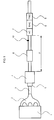
- the invention will now be described in the following with reference to a preferred embodiment and the accompanying drawing, in which an apparatus according to the invention is shown.
- the exhausts from a combustion engine 1 are led via a primary tube 2 to an exhaust pipe 3.
- the first converter 4 may be provided with a separate electrically heated first start converter 5, which is built around a carrier which is arranged within a metal casing, said carrier acting as a resistive load which can be connected to a (not shown) electric source for heating.
- a start converter which is suitable for use in the present invention is disclosed in the Swedish patent application No 9100541-3.
- the first catalytic converter 4 reaches its normal operating temperature ("light-off temperature”), and accordingly its optimum cleaning capacity, after a certain time t ign has elapsed from the start of the engine 1. Normally, t ign is about 100 seconds.
- the exhaust system of the vehicle also comprises a silencer 6 of a conventional design.
- a hydrocarbon-trap 7 which comprises a zeolitic adsorbent is arranged in the exhaust system.
- a second start converter 8 which in accordance with the first start converter 5 is electrically heated by means of a not shown source of current.
- a second converter 9 Downstream the second start converter 8 is a second converter 9 arranged which may be of conventional three-way type or may at least be HC-eliminating.
- the hydrocarbon-trap 7 is located at a certain distance x, measured along the extension of the exhaust conduit, from a point immediately downstream the first converter 4.
- the optimal location of the of the hydrocarbon-trap 7, i.e. the selection of the distance x, is decided according to what is described in the following with information about how the temperature changes inside the exhaust system after the start of the engine 1.
- the exhaust system dimensioned with reference to e.g. volume and length, so that the temperature of the hydrocarbon-trap 7, which rises after start of the engine and heats the converters because of the supply of heat by the exhausts, reaches the temperature when desorption starts first after or at earliest at the same time as the first converter 4 lights off, i.e. reaches active temperature.
- the hot exhaust stream After start of the motor 1, the hot exhaust stream will gradually cause an increase in temperature along the exhaust system.
- T d The limit temperature T d depends both upon material parameters for the hydrocarbon-trap 7, and also upon motor-technical parameters like engine temperature and exhaust flow.
- the limit temperature T d is normally about 75° C. The further away from the first converter 4 the hydrocarbon-trap 7 is located (i.e. the higher value of the distance x), the longer time it takes before the hydrocarbon-trap 7 will reach its limit temperature T d .
- desorption starts when a certain time t d has passed after start of the engine 1, which time t d is primarily depending upon the limit temperature T d and the distance x.
- the distance x is selected so that the time t ign that passes from the start of the engine 1 until the first converter 4 reaches its normal operating temperature is substantially equal to the time t d that passes before the hydrocarbon-trap 7 reaches its limit temperature T d (provided a certain value on the distance x).
- the value of the time t d may be somewhat higher than t ign , because the first converter 4 has already started operating at this point of time.
- the hydrocarbon-trap 7 can be located adjacent a second start converter 8. Nearby this is placed a second catalytic converter 9 which provides for that HC-compounds desorbing from the hydrocarbon-trap 7 (as well as other NO X - and CO-pollution) are cleaned after start of the desorption from the hydrocarbon-trap 7. Therefore, when the hydrocarbon-trap 7 has reached its limit temperature T d , the second catalytic converter 9 must have ignited, or alternatively ignite as soon as possible.
- a temperature sensor 10 can be arranged immediately upstream the hydrocarbon-trap 7, which sensor may consist of a thermocouple, a resistive sensing element or a bimetallic sensing element.
- the temperature sensor 10 can register the temperature in the exhaust stream and deliver test data in the form of a signal to a (not shown) control unit, preferably in the form of a time relay. This is in its turn connected to the (not shown) source of current, so that the second start converter 8 will be activated when the limit temperature T d of the hydrocarbon-trap 7 is reached.
- the temperature sensor 10 can be located further upstream in the exhaust system than immediately upstream the hydrocarbon-trap 7.
- the temperature value at which the temperature sensor 10 shall provide a signal to activate the second start converter 8 should be adjusted to a value which is somewhat higher than the normal limit temperature T d .
- This compensation is made on account of that the temperature further upstream in the exhaust system normally is higher than immediately upstream the hydrocarbon-trap 7.
- An advantage with this arrangement is that the temperature sensor 10 does not have to be located directly in connection to the hydrocarbon-trap 7. It is also possible to locate the temperature sensor at a distance upstream the hydrocarbon-trap 7, but it is allotted the same limit value T d as if it was located adjacent the hydrocarbon-trap 7.
- One advantage with this is that when the limit temperature T d has been reached (at the hydrocarbon-trap 7), the second start converter 8 and the second catalytic converter 9 has already been activated, and already operates normally when desorption starts in the hydrocarbon-trap 7.
Landscapes
- Engineering & Computer Science (AREA)
- Chemical & Material Sciences (AREA)
- Combustion & Propulsion (AREA)
- Mechanical Engineering (AREA)
- General Engineering & Computer Science (AREA)
- Chemical Kinetics & Catalysis (AREA)
- Health & Medical Sciences (AREA)
- Biomedical Technology (AREA)
- Environmental & Geological Engineering (AREA)
- Analytical Chemistry (AREA)
- General Chemical & Material Sciences (AREA)
- Oil, Petroleum & Natural Gas (AREA)
- Toxicology (AREA)
- Exhaust Gas After Treatment (AREA)
Description
- The present invention refers to an internal combustion engine including an apparatus for catalytic exhaust gas cleaning for the engine, comprising a first catalytic converter located downstream the engine, a hydrocarbon trap arranged at a certain distance from a point directly downstream the first catalytic converter, and a second catalytic converter located in connection with the hydrocarbon trap.
- Current motor vehicles are often provided with catalytic converters for cleaning the exhaust gas of the vehicle. Normally, current catalytic converters are not able to function with their full cleaning capacity during a cold start of the vehicle. Therefore, such a converter may be supplemented with another electrically heated converter, a so called start converter or a start-up-converter which is located upstream the regular converter. By heating the start converter electrically during start of the engine, the period for warming the regular converter is reduced, which leads to an enhanced cleaning effect. An arrangement of this kind is described in the Swedish patent application 9100541-3.
- Of the pollution (primarily HC-, NOX-, and CO-pollution) which are emitted by the engine, especially the emissions of HC-pollution are high directly after engine start. Owing to this, it is known to use a so called "hydrocarbon-trap" which can be located in the exhaust system between the engine and the regular catalytic converter. The hydrocarbon-trap which may be manufactured from a zeolitic material, can adsorb, i.e. "collect", the HC-pollution which are emitted by the engine until the regular converter has reached its normal operating temperature, and also its full cleaning capacity.
- When the temperature in the exhaust stream, and thus also in the hydrocarbon-trap, surpasses a certain limit, the hydrocarbon-trap will emit (desorb) the previously collected HC-compounds. In this way, hazardous HC-compound emissions can be reduced during the heating phase for the following converter, when its temperature is too low to obtain an optimal cleaning function. A conventional three-way catalytic converter may be arranged downstream the hydrocarbon-trap, for elimination of the desorbed HC-compounds.
- The invention is especially aimed at a so called "tailpipe catalyst", i.e. an apparatus for catalytic conversion in connection with motor vehicles, which apparatus comprises a conventional three-way catalytic converter in combination with an electrically heated start converter and a hydrocarbon-trap. Such an apparatus is already disclosed in the patent document EP 485179, in which is shown (see Fig. 1 (e), and
side 5, lines 41-48) an arrangement with a three-way catalytic converter which has been located downstream the engine. The exhausts from the engine are conducted through the converter and further to an electrically heated start converter. Further along downstream in the exhaust system is another three-way catalytic converter arranged. - One drawback with the apparatus according to EP 485179 is that it does not pay regard to the fact that the hydrocarbon-trap must be located in an optimum position with relation to the ordinary catalytic converter, in order to achieve a satisfactory cleaning function in the exhaust system. If the distance between the regular catalytic converter and the hydrocarbon-trap is small, the latter will be heated too rapidly to the limit temperature where desorption starts. Thus, there is a risk of desorption in the hydrocarbon-trap starting before the regular converter has "ignited" (which normally takes about 100 seconds from start of the engine), which in its turn causes that the HC-compounds which thereafter are emitted neither are cleaned by the regular converter nor are adsorbed by the hydrocarbon-trap.
- If, on the other hand, the distance between the ordinary converter and the hydrocarbon-trap is large, the limit temperature of the hydrocarbon-trap will be reached very late. This can mean that desorption within the hydrocarbon-trap occurs under uncontrollable conditions.
- US patent 5.315.824 describes an apparatus in which a hydrocarbon trap is arranged between two catalysts. The thermal energy of the exhaust gas passing through the catalysts located upstream the HC-trap is transferred to heat said catalyst until it has been activated. Thus the temperature of the HC adsorbent remains low for a relatively long period of time until the second catalyst has been warmed-up and the HC adsorbent can absorb the HC included in the exhaust gas for a relatively long time. A temperature sensor downstream of the HC-trap controls a heater for the downstream catalyst.
- The object of the present invention is to achieve an enhanced cleaning capacity for the exhausts from a motor vehicle, especially in connection with cold starts of the vehicle, by letting a larger amount of pollution be subjected to cleaning during the time when the regular converter still has not reached its normal operating temperature. This is achieved by an apparatus according to the preliminary wherein the distance (x) between the first catalytic converter and the hydrocarbon trap is selected so that the period of time (td) that elapses from the starting of the engine until that desorption occurs in the hydrocarbon trap is larger than or equal to the period of time (tign) that elapses from the start of the engine and until the first catalytic converter lights up to its normal operating temperature, and wherein an electrically heated start converter is located downstream the hydrocarbon trap, that the second catalytic converter is located nearby the start converter, and a temperature sensor is arranged to submit a control signal for activation of the start converter when reaching a certain temperature limit (Td) which corresponds to desorption in the hydrocarbon trap.
- The invention will now be described in the following with reference to a preferred embodiment and the accompanying drawing, in which an apparatus according to the invention is shown. The exhausts from a combustion engine 1 are led via a
primary tube 2 to anexhaust pipe 3. A first catalytic converter 4, preferably of conventional three-way type, is connected to theexhaust pipe 3. - The first converter 4 may be provided with a separate electrically heated
first start converter 5, which is built around a carrier which is arranged within a metal casing, said carrier acting as a resistive load which can be connected to a (not shown) electric source for heating. A start converter which is suitable for use in the present invention is disclosed in the Swedish patent application No 9100541-3. - The first catalytic converter 4 reaches its normal operating temperature ("light-off temperature"), and accordingly its optimum cleaning capacity, after a certain time tign has elapsed from the start of the engine 1. Normally, tign is about 100 seconds.
- The exhaust system of the vehicle also comprises a
silencer 6 of a conventional design. - Furthermore, a hydrocarbon-
trap 7 which comprises a zeolitic adsorbent is arranged in the exhaust system. In connection with the hydrocarbon-trap, there is arranged a second start converter 8 which in accordance with thefirst start converter 5 is electrically heated by means of a not shown source of current. Downstream the second start converter 8 is a second converter 9 arranged which may be of conventional three-way type or may at least be HC-eliminating. - The hydrocarbon-
trap 7 is located at a certain distance x, measured along the extension of the exhaust conduit, from a point immediately downstream the first converter 4. The optimal location of the of the hydrocarbon-trap 7, i.e. the selection of the distance x, is decided according to what is described in the following with information about how the temperature changes inside the exhaust system after the start of the engine 1. Thus, the exhaust system dimensioned with reference to e.g. volume and length, so that the temperature of the hydrocarbon-trap 7, which rises after start of the engine and heats the converters because of the supply of heat by the exhausts, reaches the temperature when desorption starts first after or at earliest at the same time as the first converter 4 lights off, i.e. reaches active temperature. - When the engine 1 has just been started, and still is cold, the contents of HC-compounds in the exhausts are comparatively large. As the first converter 4 still has not reached its normal operating temperature (which means that the initially emitted amount of HC-compounds will not be eliminated), it is necessary at this moment that the hydrocarbon-
trap 7 adsorbs, i.e. "collects", the amount of HC-compounds which are emitted. - After start of the motor 1, the hot exhaust stream will gradually cause an increase in temperature along the exhaust system. When the temperature of the hydrocarbon-
trap 7 reaches a certain limit Td, desorption in the hydrocarbon-trap 7 will start. The limit temperature Td depends both upon material parameters for the hydrocarbon-trap 7, and also upon motor-technical parameters like engine temperature and exhaust flow. The limit temperature Td is normally about 75° C. The further away from the first converter 4 the hydrocarbon-trap 7 is located (i.e. the higher value of the distance x), the longer time it takes before the hydrocarbon-trap 7 will reach its limit temperature Td. - Thus, desorption starts when a certain time td has passed after start of the engine 1, which time td is primarily depending upon the limit temperature Td and the distance x.
- When the HC-compounds are beginning to desorb from the hydrocarbon-
trap 7, it is necessary that the first converter 4 has reached its normal operating temperature and is able to clean the exhausts which thereafter are emitted by the engine 1. This is necessary, because the amount of HC-compounds which thereafter will be emitted by the engine 1 will not be adsorbed by the hydrocarbon-trap 7 (on account of that it already has reached its limit temperature Td). - In order to achieve an optimal location for the hydrocarbon-
trap 7, the distance x is selected so that the time tign that passes from the start of the engine 1 until the first converter 4 reaches its normal operating temperature is substantially equal to the time td that passes before the hydrocarbon-trap 7 reaches its limit temperature Td (provided a certain value on the distance x). In reality, the value of the time td may be somewhat higher than tign, because the first converter 4 has already started operating at this point of time. - As described earlier, the hydrocarbon-
trap 7 can be located adjacent a second start converter 8. Nearby this is placed a second catalytic converter 9 which provides for that HC-compounds desorbing from the hydrocarbon-trap 7 (as well as other NOX- and CO-pollution) are cleaned after start of the desorption from the hydrocarbon-trap 7. Therefore, when the hydrocarbon-trap 7 has reached its limit temperature Td, the second catalytic converter 9 must have ignited, or alternatively ignite as soon as possible. In order to register when the hydrocarbon-trap 7 starts to desorb, atemperature sensor 10 can be arranged immediately upstream the hydrocarbon-trap 7, which sensor may consist of a thermocouple, a resistive sensing element or a bimetallic sensing element. Thetemperature sensor 10 can register the temperature in the exhaust stream and deliver test data in the form of a signal to a (not shown) control unit, preferably in the form of a time relay. This is in its turn connected to the (not shown) source of current, so that the second start converter 8 will be activated when the limit temperature Td of the hydrocarbon-trap 7 is reached. - The
temperature sensor 10 can be located further upstream in the exhaust system than immediately upstream the hydrocarbon-trap 7. In this case, the temperature value at which thetemperature sensor 10 shall provide a signal to activate the second start converter 8, should be adjusted to a value which is somewhat higher than the normal limit temperature Td. This compensation is made on account of that the temperature further upstream in the exhaust system normally is higher than immediately upstream the hydrocarbon-trap 7. An advantage with this arrangement is that thetemperature sensor 10 does not have to be located directly in connection to the hydrocarbon-trap 7. It is also possible to locate the temperature sensor at a distance upstream the hydrocarbon-trap 7, but it is allotted the same limit value Td as if it was located adjacent the hydrocarbon-trap 7. One advantage with this is that when the limit temperature Td has been reached (at the hydrocarbon-trap 7), the second start converter 8 and the second catalytic converter 9 has already been activated, and already operates normally when desorption starts in the hydrocarbon-trap 7. - It is also possible, by way of practical experiments, to determine an estimated value tdd on the time which is expected to pass from the start of the engine 1, until that the hydrocarbon-
trap 7 is expected to have reached its limit temperature Td. After that this time tdd has elapsed, the second start converter 8 will be activated. In this case, aseparate temperature sensor 10 is not necessary. - Finally, an advantageous effect is achieved by the invention with regard to evilsmelling emissions of hydrogen sulphide, which may occur because of chemical binding of sulphur in the motor fuel in a three-way catalytic converter. For example, during maximum throttle accelerations (when fuel mixture delivered to the engine is comparatively rich) hydrogen, which is released in the combustion process, can be combined with sulphur present in the converter and form hydrogen sulphide, H2S. This problem can be solved by the present invention, which accordingly is built up around a "tailpipe catalyst" comprising among other a three-way converter 9. In this second converter 9, the H2S-compounds will be reduced to SO2, which is a much less offensive gas than H2S.
Claims (3)
- An internal combustion engine including an apparatus for catalytic exhaust gas cleaning for the engine (1), comprising a first catalytic converter (4) located downstream the engine (1), a hydrocarbon trap (7) arranged at a certain distance (x) from a point directly downstream the first catalytic converter (4), and a second catalytic converter (9) located in connection with the hydrocarbon trap (7), wherein the distance (x) between the first catalytic converter (4) and the hydrocarbon trap (7) is selected so that the period of time (td) that elapses from the starting of the engine (1) until that desorption occurs in the hydrocarbon trap (7) is larger than or equal to the period of time (tign) that elapses from the start of the engine (1) and until the first catalytic converter (4) lights up to its normal operating temperature, wherein an electrically heated start converter (8) is located downstream the hydrocarbon trap (7), wherein the second catalytic converter (9) is located nearby the start converter (8), and a temperature sensor (10) is located upstream the hydrocarbon trap (7), which temperature sensor (10) is arranged to submit a control signal for activation of the start converter (8) when reaching a certain temperature limit (Td) which corresponds to desorption in the hydrocarbon trap (7).
- An internal combustion engine according to claim 1, characterized in that the second catalytic converter (9) is located downstream the start converter (8).
- An internal combustion engine according to any of the preceeding claims , characterized in that a further electrically heated start converter (5) is located upstream the first catalytic converter (4).
Applications Claiming Priority (2)
| Application Number | Priority Date | Filing Date | Title |
|---|---|---|---|
| SE9302407A SE501464C2 (en) | 1993-07-09 | 1993-07-09 | Device for catalytic cleaning of exhaust gases from IC engine - comprises first catalyser placed downstream of engine, an HC trap, and second catalyser arranged in connection with HC trap |
| PCT/SE1994/001150 WO1996017157A1 (en) | 1993-07-09 | 1994-11-30 | Apparatus for catalytic exhaust gas cleaning |
Publications (2)
| Publication Number | Publication Date |
|---|---|
| EP0828927A1 EP0828927A1 (en) | 1998-03-18 |
| EP0828927B1 true EP0828927B1 (en) | 2001-01-17 |
Family
ID=26661801
Family Applications (1)
| Application Number | Title | Priority Date | Filing Date |
|---|---|---|---|
| EP95906570A Expired - Lifetime EP0828927B1 (en) | 1993-07-09 | 1994-11-30 | Apparatus for catalytic exhaust gas cleaning |
Country Status (6)
| Country | Link |
|---|---|
| US (1) | US5914090A (en) |
| EP (1) | EP0828927B1 (en) |
| JP (1) | JPH10510023A (en) |
| DE (1) | DE69426609T2 (en) |
| SE (1) | SE501464C2 (en) |
| WO (1) | WO1996017157A1 (en) |
Families Citing this family (11)
| Publication number | Priority date | Publication date | Assignee | Title |
|---|---|---|---|---|
| SE506971C2 (en) * | 1996-07-22 | 1998-03-09 | Volvo Ab | Method and apparatus for exhaust gas purification by means of a canister |
| JPH1181999A (en) * | 1997-09-12 | 1999-03-26 | Honda Motor Co Ltd | Exhaust gas purification device for internal combustion engine |
| DE19806033A1 (en) * | 1998-02-13 | 1999-08-19 | Emitec Emissionstechnologie | Arrangement and method for implementing at least one exhaust gas component of an exhaust gas stream of an internal combustion engine |
| US6447735B1 (en) * | 1998-04-30 | 2002-09-10 | Nissan Motor Co., Ltd. | Exhaust purifier and manufacturing method of same |
| JP3402200B2 (en) * | 1998-06-01 | 2003-04-28 | 日産自動車株式会社 | Exhaust gas purification device for internal combustion engine |
| DE10051562A1 (en) * | 2000-10-18 | 2002-04-25 | Emitec Emissionstechnologie | Electrically heated honeycomb body used for removing hydrocarbons or nitrogen oxides from I.C. engine exhaust gases comprises two zones with different coatings arranged behind each other in the flow direction |
| JP2003201832A (en) * | 2001-10-25 | 2003-07-18 | Nissan Motor Co Ltd | Exhaust gas purification catalyst system |
| US8375701B2 (en) | 2008-07-30 | 2013-02-19 | Ford Global Technologies, Llc | Hydrocarbon retaining and purging system |
| US10634078B2 (en) * | 2017-12-11 | 2020-04-28 | Ford Global Technologies, Llc | Methods and systems for an exhaust aftertreatment device |
| FR3107727B1 (en) * | 2020-02-28 | 2022-11-04 | Faurecia Systemes Dechappement | Exhaust line |
| DE102020214870B3 (en) | 2020-11-26 | 2022-05-12 | Vitesco Technologies GmbH | Device for exhaust aftertreatment |
Citations (1)
| Publication number | Priority date | Publication date | Assignee | Title |
|---|---|---|---|---|
| US5315824A (en) * | 1991-08-29 | 1994-05-31 | Toyota Jidosha Kabushiki Kaisha | Cold HC adsorption and removal apparatus for an internal combustion engine |
Family Cites Families (3)
| Publication number | Priority date | Publication date | Assignee | Title |
|---|---|---|---|---|
| US5296198A (en) * | 1990-11-09 | 1994-03-22 | Ngk Insulators, Ltd. | Heater and catalytic converter |
| SE500701C2 (en) * | 1991-02-22 | 1994-08-15 | Volvo Ab | Catalytic exhaust gas purification method and device for vehicles with electrically heated starting catalyst |
| US5271906A (en) * | 1991-10-28 | 1993-12-21 | Toyota Jidosha Kabushiki Kaisha | Exhaust emission control apparatus using catalytic converter with hydrocarbon absorbent |
-
1993
- 1993-07-09 SE SE9302407A patent/SE501464C2/en not_active IP Right Cessation
-
1994
- 1994-11-30 DE DE69426609T patent/DE69426609T2/en not_active Expired - Fee Related
- 1994-11-30 US US08/849,419 patent/US5914090A/en not_active Expired - Fee Related
- 1994-11-30 JP JP8518656A patent/JPH10510023A/en active Pending
- 1994-11-30 WO PCT/SE1994/001150 patent/WO1996017157A1/en not_active Ceased
- 1994-11-30 EP EP95906570A patent/EP0828927B1/en not_active Expired - Lifetime
Patent Citations (1)
| Publication number | Priority date | Publication date | Assignee | Title |
|---|---|---|---|---|
| US5315824A (en) * | 1991-08-29 | 1994-05-31 | Toyota Jidosha Kabushiki Kaisha | Cold HC adsorption and removal apparatus for an internal combustion engine |
Also Published As
| Publication number | Publication date |
|---|---|
| SE501464C2 (en) | 1995-02-20 |
| WO1996017157A1 (en) | 1996-06-06 |
| US5914090A (en) | 1999-06-22 |
| SE9302407D0 (en) | 1993-07-09 |
| DE69426609T2 (en) | 2001-08-30 |
| EP0828927A1 (en) | 1998-03-18 |
| SE9302407L (en) | 1995-01-10 |
| JPH10510023A (en) | 1998-09-29 |
| DE69426609D1 (en) | 2001-02-22 |
Similar Documents
| Publication | Publication Date | Title |
|---|---|---|
| JP3311051B2 (en) | Exhaust gas purification method and apparatus | |
| EP0639699B1 (en) | Exhaust gas purification system and exhaust gas purification method | |
| CA2103647C (en) | A catalytic automotive emission control process with improved cold-start behavior | |
| US5939028A (en) | Combatting air pollution | |
| US5613359A (en) | Method and apparatus for reducing hydrocarbon emissions for an internal combustion engine | |
| JP3709953B2 (en) | Exhaust gas purification device for internal combustion engine | |
| US5914090A (en) | Apparatus for catalytic exhaust gas cleaning | |
| JPH0559942A (en) | Cold HC adsorption / removal device | |
| EP1283947B1 (en) | Method of treating gasoline exhaust gases | |
| JP2005299631A (en) | Automobile exhaust emission control system | |
| US6155044A (en) | Exhaust gas purifying system for internal combustion engine | |
| JP2002503784A (en) | Apparatus for converting components in exhaust gas stream of internal combustion engine and method of operating the same | |
| KR20010033964A (en) | Heatable catalytic converter arrangement having a water trap located upstream | |
| JP2010127151A (en) | Exhaust emission control device for internal combustion engine | |
| EP0886041A3 (en) | System for exhaust gas purification | |
| JP2946064B2 (en) | Engine exhaust purification device | |
| JP2694739B2 (en) | Engine exhaust purification device | |
| KR100332079B1 (en) | Apparatus for catalytic exhaust gas cleaning | |
| JP4258871B2 (en) | Exhaust gas purification device | |
| JP3596113B2 (en) | Exhaust gas purification device for internal combustion engine | |
| JPH116424A (en) | Exhaust gas purification device for internal combustion engine | |
| JP3055270B2 (en) | Exhaust gas purification device for internal combustion engine | |
| JP3465584B2 (en) | Exhaust gas purification device for internal combustion engine | |
| JPH0797916A (en) | Engine exhaust purification device | |
| JP3343948B2 (en) | Exhaust gas purification device |
Legal Events
| Date | Code | Title | Description |
|---|---|---|---|
| PUAI | Public reference made under article 153(3) epc to a published international application that has entered the european phase |
Free format text: ORIGINAL CODE: 0009012 |
|
| 17P | Request for examination filed |
Effective date: 19970625 |
|
| AK | Designated contracting states |
Kind code of ref document: A1 Designated state(s): DE ES FR GB IT NL |
|
| 17Q | First examination report despatched |
Effective date: 19990301 |
|
| GRAG | Despatch of communication of intention to grant |
Free format text: ORIGINAL CODE: EPIDOS AGRA |
|
| GRAG | Despatch of communication of intention to grant |
Free format text: ORIGINAL CODE: EPIDOS AGRA |
|
| GRAH | Despatch of communication of intention to grant a patent |
Free format text: ORIGINAL CODE: EPIDOS IGRA |
|
| GRAH | Despatch of communication of intention to grant a patent |
Free format text: ORIGINAL CODE: EPIDOS IGRA |
|
| GRAA | (expected) grant |
Free format text: ORIGINAL CODE: 0009210 |
|
| AK | Designated contracting states |
Kind code of ref document: B1 Designated state(s): DE ES FR GB IT NL |
|
| PG25 | Lapsed in a contracting state [announced via postgrant information from national office to epo] |
Ref country code: NL Free format text: LAPSE BECAUSE OF FAILURE TO SUBMIT A TRANSLATION OF THE DESCRIPTION OR TO PAY THE FEE WITHIN THE PRESCRIBED TIME-LIMIT Effective date: 20010117 Ref country code: IT Free format text: LAPSE BECAUSE OF FAILURE TO SUBMIT A TRANSLATION OF THE DESCRIPTION OR TO PAY THE FEE WITHIN THE PRE;WARNING: LAPSES OF ITALIAN PATENTS WITH EFFECTIVE DATE BEFORE 2007 MAY HAVE OCCURRED AT ANY TIME BEFORE 2007. THE CORRECT EFFECTIVE DATE MAY BE DIFFERENT FROM THE ONE RECORDED.SCRIBED TIME-LIMIT Effective date: 20010117 Ref country code: ES Free format text: THE PATENT HAS BEEN ANNULLED BY A DECISION OF A NATIONAL AUTHORITY Effective date: 20010117 |
|
| REF | Corresponds to: |
Ref document number: 69426609 Country of ref document: DE Date of ref document: 20010222 |
|
| ET | Fr: translation filed | ||
| NLV1 | Nl: lapsed or annulled due to failure to fulfill the requirements of art. 29p and 29m of the patents act | ||
| REG | Reference to a national code |
Ref country code: GB Ref legal event code: 732E |
|
| REG | Reference to a national code |
Ref country code: FR Ref legal event code: TP |
|
| PLBE | No opposition filed within time limit |
Free format text: ORIGINAL CODE: 0009261 |
|
| STAA | Information on the status of an ep patent application or granted ep patent |
Free format text: STATUS: NO OPPOSITION FILED WITHIN TIME LIMIT |
|
| REG | Reference to a national code |
Ref country code: GB Ref legal event code: IF02 |
|
| 26N | No opposition filed | ||
| PGFP | Annual fee paid to national office [announced via postgrant information from national office to epo] |
Ref country code: FR Payment date: 20041105 Year of fee payment: 11 |
|
| PG25 | Lapsed in a contracting state [announced via postgrant information from national office to epo] |
Ref country code: FR Free format text: LAPSE BECAUSE OF NON-PAYMENT OF DUE FEES Effective date: 20060731 |
|
| REG | Reference to a national code |
Ref country code: FR Ref legal event code: ST Effective date: 20060731 |
|
| PGFP | Annual fee paid to national office [announced via postgrant information from national office to epo] |
Ref country code: DE Payment date: 20081128 Year of fee payment: 15 |
|
| PGFP | Annual fee paid to national office [announced via postgrant information from national office to epo] |
Ref country code: GB Payment date: 20081008 Year of fee payment: 15 |
|
| GBPC | Gb: european patent ceased through non-payment of renewal fee |
Effective date: 20091130 |
|
| PG25 | Lapsed in a contracting state [announced via postgrant information from national office to epo] |
Ref country code: DE Free format text: LAPSE BECAUSE OF NON-PAYMENT OF DUE FEES Effective date: 20100601 |
|
| PG25 | Lapsed in a contracting state [announced via postgrant information from national office to epo] |
Ref country code: GB Free format text: LAPSE BECAUSE OF NON-PAYMENT OF DUE FEES Effective date: 20091130 |