EP0828623B1 - Drive system for hybrid electric vehicle - Google Patents
Drive system for hybrid electric vehicle Download PDFInfo
- Publication number
- EP0828623B1 EP0828623B1 EP96916871A EP96916871A EP0828623B1 EP 0828623 B1 EP0828623 B1 EP 0828623B1 EP 96916871 A EP96916871 A EP 96916871A EP 96916871 A EP96916871 A EP 96916871A EP 0828623 B1 EP0828623 B1 EP 0828623B1
- Authority
- EP
- European Patent Office
- Prior art keywords
- drive system
- operatively connected
- vehicle
- torque
- drive
- Prior art date
- Legal status (The legal status is an assumption and is not a legal conclusion. Google has not performed a legal analysis and makes no representation as to the accuracy of the status listed.)
- Expired - Lifetime
Links
Images


Classifications
-
- B—PERFORMING OPERATIONS; TRANSPORTING
- B60—VEHICLES IN GENERAL
- B60K—ARRANGEMENT OR MOUNTING OF PROPULSION UNITS OR OF TRANSMISSIONS IN VEHICLES; ARRANGEMENT OR MOUNTING OF PLURAL DIVERSE PRIME-MOVERS IN VEHICLES; AUXILIARY DRIVES FOR VEHICLES; INSTRUMENTATION OR DASHBOARDS FOR VEHICLES; ARRANGEMENTS IN CONNECTION WITH COOLING, AIR INTAKE, GAS EXHAUST OR FUEL SUPPLY OF PROPULSION UNITS IN VEHICLES
- B60K6/00—Arrangement or mounting of plural diverse prime-movers for mutual or common propulsion, e.g. hybrid propulsion systems comprising electric motors and internal combustion engines
- B60K6/20—Arrangement or mounting of plural diverse prime-movers for mutual or common propulsion, e.g. hybrid propulsion systems comprising electric motors and internal combustion engines the prime-movers consisting of electric motors and internal combustion engines, e.g. HEVs
- B60K6/42—Arrangement or mounting of plural diverse prime-movers for mutual or common propulsion, e.g. hybrid propulsion systems comprising electric motors and internal combustion engines the prime-movers consisting of electric motors and internal combustion engines, e.g. HEVs characterised by the architecture of the hybrid electric vehicle
- B60K6/44—Series-parallel type
- B60K6/442—Series-parallel switching type
-
- B—PERFORMING OPERATIONS; TRANSPORTING
- B60—VEHICLES IN GENERAL
- B60K—ARRANGEMENT OR MOUNTING OF PROPULSION UNITS OR OF TRANSMISSIONS IN VEHICLES; ARRANGEMENT OR MOUNTING OF PLURAL DIVERSE PRIME-MOVERS IN VEHICLES; AUXILIARY DRIVES FOR VEHICLES; INSTRUMENTATION OR DASHBOARDS FOR VEHICLES; ARRANGEMENTS IN CONNECTION WITH COOLING, AIR INTAKE, GAS EXHAUST OR FUEL SUPPLY OF PROPULSION UNITS IN VEHICLES
- B60K26/00—Arrangement or mounting of propulsion-unit control devices in vehicles
- B60K26/02—Arrangement or mounting of propulsion-unit control devices in vehicles of initiating means or elements
-
- B—PERFORMING OPERATIONS; TRANSPORTING
- B60—VEHICLES IN GENERAL
- B60L—PROPULSION OF ELECTRICALLY-PROPELLED VEHICLES; SUPPLYING ELECTRIC POWER FOR AUXILIARY EQUIPMENT OF ELECTRICALLY-PROPELLED VEHICLES; ELECTRODYNAMIC BRAKE SYSTEMS FOR VEHICLES IN GENERAL; MAGNETIC SUSPENSION OR LEVITATION FOR VEHICLES; MONITORING OPERATING VARIABLES OF ELECTRICALLY-PROPELLED VEHICLES; ELECTRIC SAFETY DEVICES FOR ELECTRICALLY-PROPELLED VEHICLES
- B60L15/00—Methods, circuits, or devices for controlling the traction-motor speed of electrically-propelled vehicles
- B60L15/20—Methods, circuits, or devices for controlling the traction-motor speed of electrically-propelled vehicles for control of the vehicle or its driving motor to achieve a desired performance, e.g. speed, torque, programmed variation of speed
- B60L15/2054—Methods, circuits, or devices for controlling the traction-motor speed of electrically-propelled vehicles for control of the vehicle or its driving motor to achieve a desired performance, e.g. speed, torque, programmed variation of speed by controlling transmissions or clutches
-
- B—PERFORMING OPERATIONS; TRANSPORTING
- B60—VEHICLES IN GENERAL
- B60L—PROPULSION OF ELECTRICALLY-PROPELLED VEHICLES; SUPPLYING ELECTRIC POWER FOR AUXILIARY EQUIPMENT OF ELECTRICALLY-PROPELLED VEHICLES; ELECTRODYNAMIC BRAKE SYSTEMS FOR VEHICLES IN GENERAL; MAGNETIC SUSPENSION OR LEVITATION FOR VEHICLES; MONITORING OPERATING VARIABLES OF ELECTRICALLY-PROPELLED VEHICLES; ELECTRIC SAFETY DEVICES FOR ELECTRICALLY-PROPELLED VEHICLES
- B60L50/00—Electric propulsion with power supplied within the vehicle
- B60L50/10—Electric propulsion with power supplied within the vehicle using propulsion power supplied by engine-driven generators, e.g. generators driven by combustion engines
- B60L50/16—Electric propulsion with power supplied within the vehicle using propulsion power supplied by engine-driven generators, e.g. generators driven by combustion engines with provision for separate direct mechanical propulsion
-
- B—PERFORMING OPERATIONS; TRANSPORTING
- B60—VEHICLES IN GENERAL
- B60L—PROPULSION OF ELECTRICALLY-PROPELLED VEHICLES; SUPPLYING ELECTRIC POWER FOR AUXILIARY EQUIPMENT OF ELECTRICALLY-PROPELLED VEHICLES; ELECTRODYNAMIC BRAKE SYSTEMS FOR VEHICLES IN GENERAL; MAGNETIC SUSPENSION OR LEVITATION FOR VEHICLES; MONITORING OPERATING VARIABLES OF ELECTRICALLY-PROPELLED VEHICLES; ELECTRIC SAFETY DEVICES FOR ELECTRICALLY-PROPELLED VEHICLES
- B60L50/00—Electric propulsion with power supplied within the vehicle
- B60L50/50—Electric propulsion with power supplied within the vehicle using propulsion power supplied by batteries or fuel cells
- B60L50/60—Electric propulsion with power supplied within the vehicle using propulsion power supplied by batteries or fuel cells using power supplied by batteries
- B60L50/61—Electric propulsion with power supplied within the vehicle using propulsion power supplied by batteries or fuel cells using power supplied by batteries by batteries charged by engine-driven generators, e.g. series hybrid electric vehicles
-
- B—PERFORMING OPERATIONS; TRANSPORTING
- B60—VEHICLES IN GENERAL
- B60L—PROPULSION OF ELECTRICALLY-PROPELLED VEHICLES; SUPPLYING ELECTRIC POWER FOR AUXILIARY EQUIPMENT OF ELECTRICALLY-PROPELLED VEHICLES; ELECTRODYNAMIC BRAKE SYSTEMS FOR VEHICLES IN GENERAL; MAGNETIC SUSPENSION OR LEVITATION FOR VEHICLES; MONITORING OPERATING VARIABLES OF ELECTRICALLY-PROPELLED VEHICLES; ELECTRIC SAFETY DEVICES FOR ELECTRICALLY-PROPELLED VEHICLES
- B60L2240/00—Control parameters of input or output; Target parameters
- B60L2240/40—Drive Train control parameters
- B60L2240/42—Drive Train control parameters related to electric machines
- B60L2240/423—Torque
-
- B—PERFORMING OPERATIONS; TRANSPORTING
- B60—VEHICLES IN GENERAL
- B60L—PROPULSION OF ELECTRICALLY-PROPELLED VEHICLES; SUPPLYING ELECTRIC POWER FOR AUXILIARY EQUIPMENT OF ELECTRICALLY-PROPELLED VEHICLES; ELECTRODYNAMIC BRAKE SYSTEMS FOR VEHICLES IN GENERAL; MAGNETIC SUSPENSION OR LEVITATION FOR VEHICLES; MONITORING OPERATING VARIABLES OF ELECTRICALLY-PROPELLED VEHICLES; ELECTRIC SAFETY DEVICES FOR ELECTRICALLY-PROPELLED VEHICLES
- B60L2240/00—Control parameters of input or output; Target parameters
- B60L2240/40—Drive Train control parameters
- B60L2240/44—Drive Train control parameters related to combustion engines
- B60L2240/443—Torque
-
- B—PERFORMING OPERATIONS; TRANSPORTING
- B60—VEHICLES IN GENERAL
- B60L—PROPULSION OF ELECTRICALLY-PROPELLED VEHICLES; SUPPLYING ELECTRIC POWER FOR AUXILIARY EQUIPMENT OF ELECTRICALLY-PROPELLED VEHICLES; ELECTRODYNAMIC BRAKE SYSTEMS FOR VEHICLES IN GENERAL; MAGNETIC SUSPENSION OR LEVITATION FOR VEHICLES; MONITORING OPERATING VARIABLES OF ELECTRICALLY-PROPELLED VEHICLES; ELECTRIC SAFETY DEVICES FOR ELECTRICALLY-PROPELLED VEHICLES
- B60L2240/00—Control parameters of input or output; Target parameters
- B60L2240/40—Drive Train control parameters
- B60L2240/50—Drive Train control parameters related to clutches
- B60L2240/507—Operating parameters
-
- B—PERFORMING OPERATIONS; TRANSPORTING
- B60—VEHICLES IN GENERAL
- B60L—PROPULSION OF ELECTRICALLY-PROPELLED VEHICLES; SUPPLYING ELECTRIC POWER FOR AUXILIARY EQUIPMENT OF ELECTRICALLY-PROPELLED VEHICLES; ELECTRODYNAMIC BRAKE SYSTEMS FOR VEHICLES IN GENERAL; MAGNETIC SUSPENSION OR LEVITATION FOR VEHICLES; MONITORING OPERATING VARIABLES OF ELECTRICALLY-PROPELLED VEHICLES; ELECTRIC SAFETY DEVICES FOR ELECTRICALLY-PROPELLED VEHICLES
- B60L2250/00—Driver interactions
- B60L2250/26—Driver interactions by pedal actuation
-
- B—PERFORMING OPERATIONS; TRANSPORTING
- B60—VEHICLES IN GENERAL
- B60L—PROPULSION OF ELECTRICALLY-PROPELLED VEHICLES; SUPPLYING ELECTRIC POWER FOR AUXILIARY EQUIPMENT OF ELECTRICALLY-PROPELLED VEHICLES; ELECTRODYNAMIC BRAKE SYSTEMS FOR VEHICLES IN GENERAL; MAGNETIC SUSPENSION OR LEVITATION FOR VEHICLES; MONITORING OPERATING VARIABLES OF ELECTRICALLY-PROPELLED VEHICLES; ELECTRIC SAFETY DEVICES FOR ELECTRICALLY-PROPELLED VEHICLES
- B60L2250/00—Driver interactions
- B60L2250/26—Driver interactions by pedal actuation
- B60L2250/28—Accelerator pedal thresholds
-
- Y—GENERAL TAGGING OF NEW TECHNOLOGICAL DEVELOPMENTS; GENERAL TAGGING OF CROSS-SECTIONAL TECHNOLOGIES SPANNING OVER SEVERAL SECTIONS OF THE IPC; TECHNICAL SUBJECTS COVERED BY FORMER USPC CROSS-REFERENCE ART COLLECTIONS [XRACs] AND DIGESTS
- Y02—TECHNOLOGIES OR APPLICATIONS FOR MITIGATION OR ADAPTATION AGAINST CLIMATE CHANGE
- Y02T—CLIMATE CHANGE MITIGATION TECHNOLOGIES RELATED TO TRANSPORTATION
- Y02T10/00—Road transport of goods or passengers
- Y02T10/60—Other road transportation technologies with climate change mitigation effect
- Y02T10/62—Hybrid vehicles
-
- Y—GENERAL TAGGING OF NEW TECHNOLOGICAL DEVELOPMENTS; GENERAL TAGGING OF CROSS-SECTIONAL TECHNOLOGIES SPANNING OVER SEVERAL SECTIONS OF THE IPC; TECHNICAL SUBJECTS COVERED BY FORMER USPC CROSS-REFERENCE ART COLLECTIONS [XRACs] AND DIGESTS
- Y02—TECHNOLOGIES OR APPLICATIONS FOR MITIGATION OR ADAPTATION AGAINST CLIMATE CHANGE
- Y02T—CLIMATE CHANGE MITIGATION TECHNOLOGIES RELATED TO TRANSPORTATION
- Y02T10/00—Road transport of goods or passengers
- Y02T10/60—Other road transportation technologies with climate change mitigation effect
- Y02T10/64—Electric machine technologies in electromobility
-
- Y—GENERAL TAGGING OF NEW TECHNOLOGICAL DEVELOPMENTS; GENERAL TAGGING OF CROSS-SECTIONAL TECHNOLOGIES SPANNING OVER SEVERAL SECTIONS OF THE IPC; TECHNICAL SUBJECTS COVERED BY FORMER USPC CROSS-REFERENCE ART COLLECTIONS [XRACs] AND DIGESTS
- Y02—TECHNOLOGIES OR APPLICATIONS FOR MITIGATION OR ADAPTATION AGAINST CLIMATE CHANGE
- Y02T—CLIMATE CHANGE MITIGATION TECHNOLOGIES RELATED TO TRANSPORTATION
- Y02T10/00—Road transport of goods or passengers
- Y02T10/60—Other road transportation technologies with climate change mitigation effect
- Y02T10/70—Energy storage systems for electromobility, e.g. batteries
-
- Y—GENERAL TAGGING OF NEW TECHNOLOGICAL DEVELOPMENTS; GENERAL TAGGING OF CROSS-SECTIONAL TECHNOLOGIES SPANNING OVER SEVERAL SECTIONS OF THE IPC; TECHNICAL SUBJECTS COVERED BY FORMER USPC CROSS-REFERENCE ART COLLECTIONS [XRACs] AND DIGESTS
- Y02—TECHNOLOGIES OR APPLICATIONS FOR MITIGATION OR ADAPTATION AGAINST CLIMATE CHANGE
- Y02T—CLIMATE CHANGE MITIGATION TECHNOLOGIES RELATED TO TRANSPORTATION
- Y02T10/00—Road transport of goods or passengers
- Y02T10/60—Other road transportation technologies with climate change mitigation effect
- Y02T10/7072—Electromobility specific charging systems or methods for batteries, ultracapacitors, supercapacitors or double-layer capacitors
-
- Y—GENERAL TAGGING OF NEW TECHNOLOGICAL DEVELOPMENTS; GENERAL TAGGING OF CROSS-SECTIONAL TECHNOLOGIES SPANNING OVER SEVERAL SECTIONS OF THE IPC; TECHNICAL SUBJECTS COVERED BY FORMER USPC CROSS-REFERENCE ART COLLECTIONS [XRACs] AND DIGESTS
- Y02—TECHNOLOGIES OR APPLICATIONS FOR MITIGATION OR ADAPTATION AGAINST CLIMATE CHANGE
- Y02T—CLIMATE CHANGE MITIGATION TECHNOLOGIES RELATED TO TRANSPORTATION
- Y02T10/00—Road transport of goods or passengers
- Y02T10/60—Other road transportation technologies with climate change mitigation effect
- Y02T10/72—Electric energy management in electromobility
Definitions
- the subject invention relates to a vehicle drive system, and more particularly, to a highly efficient drive system for a hybrid electric automobile which employs both a combustion engine and an electric motor to power the vehicle according the first part of claim 1.
- hybrid powered vehicles Automobiles utilizing both an internal combustion engine and an electric motor for power are also known in the art, and are commonly referred to as hybrid powered vehicles. These vehicles are designed to minimize harmful effluents and maximize the beneficial aspects of gas engines and electric motors. Early examples of hybrid electric vehicles are disclosed in U.S Patent No. 2,571,284 to P.T. Nims; U.S. Patent No. 3,305,965 to R. Roth; and U.S. Patent No. 3,791,473 to Rosen. In general, there are two types of hybrid electric vehicle drive systems. A parallel drive system in which the internal combustion engine and the electric motor work in conjunction to power the drive wheels of the vehicle, and a series drive system wherein the internal combustion engine powers a generator for the electric motor and the electric motor delivers power to the drive wheels of the vehicle.
- the modified drive system includes an internal combustion engine that delivers power to a front drive shaft of the vehicle and an electric motor that delivers power to a rear drive shaft of the vehicle through an automatic transmission.
- the electric motor and the automatic transmission are used to accelerate the vehicle to highway cruising speed.
- the internal combustion engine is started and a magnetic clutch connects the engine to the front drive shaft.
- the internal combustion engine can be employed to drive a generator that charges the batteries which deliver power to the electric motor.
- a hybrid electric drive system with the features of the first part of the claim 1 is known from EP 510 582 A2.
- the subject invention is directed to a highly efficient drive system for a hybrid electric vehicle with the features of claim 1.
- Means are operatively associated with the input shaft of the transmission assembly for disengaging the operative connection between the electric motor and the input shaft to facilitate the deliverance of torque to the input shaft solely from the internal combustion engine, and means are operatively associated with the secondary drive shaft for disengaging the operative connection between the internal combustion engine and the secondary drive shaft to facilitate the deliverance of torque to the input shaft of the transmission assembly solely from the electric motor.
- the vehicle drive system also includes energy storage means for storing electric energy for deliverance to the electric motor, and a generator for generating electric energy for deliverance to the energy storage means.
- the generator is connected to an output shaft of the internal combustion engine, and means are preferably provided for selectively engaging the operative connection between the internal combustion engine and the generator.
- the means for selectively engaging the operative connection between the internal combustion energy and the generator preferably comprises a solenoid clutch which is actuated when the electrical energy stored within the energy storage means falls below a predetermined minimum level.
- the means which are operatively associated with the input shaft of the transmission assembly preferably comprises an overrunning clutch assembly, as does the means which are operatively associated with the secondary drive shaft.
- the drive system of the subject invention also includes means which are associated with the secondary drive shaft for transferring torque from the drive wheels to the generator when the transmission assembly is downshifted during braking.
- the means for transferring torque comprises a solenoid clutch which is activated when a brake is applied to the drive wheels. Torque can also be transferred from the drive wheels to the generator during braking when the transmission is in gear, and the solenoid clutch is activated.
- a torque convertor assembly is operatively associated with an output shaft of the internal combustion engine and the secondary drive shaft to variably control the transmission of torque to the secondary drive shaft as the engine is accelerated from idle to full throttle.
- the drive system of the subject invention further includes means for selectively switching between a first operating mode wherein power is directly transmitted from the internal combustion engine to the primary drive shaft, and a second operating mode wherein power from the internal combustion engine is directly transmitted to the generator and power from the electric motor is directly transmitted to the primary drive shaft.
- the later operating mode being extremely useful during stop and go city driving.
- the subject invention is directed to a hybrid electric drive system which includes an internal combustion engine having first and second output shafts, a dynamotor having an input shaft and an output shaft, at least one pulley-type torque convertor assembly having a driving pulley operatively connected to the first output shaft of the engine and a driven pulley operatively connected to the input shaft of the dynamotor, a transmission assembly operatively connected to the output shaft of the dynamotor for delivering torque to the drive shaft of the vehicle, a generator operatively connected to the second output shaft of the engine for generating electrical energy, and a solenoid clutch for selectively disengaging the operative connection between the driven pulley of the torque convertor and the dynamotor to facilitate operation of the vehicle in a parallel configuration and a series configuration.
- drive system 20 includes a relatively low horsepower internal combustion engine 30 (i.e., 20 hp) and two conventional electric motors 32 and 34 (i.e., 30-60 hp; DC motors) which deliver power to the drive wheels 36 and 38 of vehicle 10, either individually or concurrently, depending upon the operating conditions of the vehicle.
- the specific power of the engine and the motors will depend upon the size and weight of the vehicle.
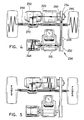
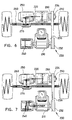
- FIG. 2-7 there is illustrated an embodiment of a vehicle drive system constructed in accordance with a preferred embodiment of the subject invention and designated generally by reference numeral 200.
- Drive system 200 does utilizing substantially few mechanical components.
- the two prime movers of vehicle drive system 200 are an internal combustion engine 210 and a 60-120 hp dynamotor 220 which has the combined capabilities of an electric motor and an electric generator.
- Drive system 200 further includes a pulley-type torque converter assembly 230 which connects one of the output shafts of engine 210 to the input shaft of dynamotor 220 and includes an input pulley 232 and an output pulley 234 connected by a drive belt 236.
- the torque convertor functions as a continuously variable transmission which gradually upshifts as the vehicle accelerates.
- a generator 240 is connected to the other output shaft of engine 210 for generating electrical energy to charge the vehicle batteries.
- Dynamotor 220 which utilizes energy stored in the batteries during certain operating conditions, is connected to the vehicle transmission 250.
- a differential 270 connects transmission 250 to drive shaft 260.
- a solenoid clutch 280 is operatively associated with the output pulley 234 of torque convertor 230 to facilitate selective switching between a parallel drive configuration and a series drive configuration.
- An overrunning clutch 290 is operatively associated with output pulley 234 for selectively disengaging the torque convertor from transmission assembly 250 to isolate combustion engine 210 when it is not being employed as a prime mover.
- combustion engine 210 is functioning as the sole prime mover of the vehicle employing drive system 200
- the mean horsepower of engine 210 is utilized to power the vehicle and the remaining horsepower is transferred to generator 240 for charging the vehicle batteries, as illustrated in Fig. 4.
- power generation is dependent upon battery charge and can be controlled electronically by means of sensors associated with a vehicle control system.
- vehicle drive system 200 is configured to employ regenerative braking to reclaim lost energy.
- regenerative braking when the vehicle is downshifted or the brakes are applied, power is transferred from the drive wheels, through drive shaft 260 and transmission assembly 250, to dynamotor 220, which under such conditions, functions as a generator to produce electrical energy to charge the batteries.
- overrunning clutch 290 is disengaged, isolating the combustion engine 210 from the rest of the drive system.
- Solenoid clutch 280 remains engaged to provide quick engine response when power is again required.
- vehicle drive system 200 when vehicle drive system 200 is operable in a zero emissions mode, dynamotor 220 is employed as the prime mover. In this instance, overrunning clutch 290 is disengaged and solenoid clutch 280 is preferably engaged.
- vehicle drive system 200 is operable in both a parallel configuration and a series configuration. In a parallel configuration, power is transferable from internal combustion engine 210 and dynamotor 220 to the drive wheels of the vehicle. In a series configuration power from dynamotors 220 is transferable to the drive wheels, and combustion engine 210 powers generator 240. To switch from a parallel mode of operation, such as those illustrated in Figs. 2-3 to a series mode of operation which is illustrated in Fig.
- solenoid clutch 290 is switched from a normally engaged position wherein the driven pulley 234 of torque convertor 230 is engaged, to a disengaged position wherein the driven pulley is disengaged to isolate the torque convertor. Switching may be accomplished manually or by way of an electronic control system.
- the belts and pulleys can be replaced by a gear box having input and output shafts for the engine, generator, and electric motors.
- the electric and gas engine throttles can be operated by computer controlled actuators instead of a mechanical system. This would allow a computer to automatically adjust the duty cycles of the internal combustion engine and electric motors to reach any desired depth of battery discharge after a specified number of miles.
Landscapes
- Engineering & Computer Science (AREA)
- Mechanical Engineering (AREA)
- Transportation (AREA)
- Power Engineering (AREA)
- Combustion & Propulsion (AREA)
- Chemical & Material Sciences (AREA)
- Sustainable Energy (AREA)
- Sustainable Development (AREA)
- Life Sciences & Earth Sciences (AREA)
- Electric Propulsion And Braking For Vehicles (AREA)
- Hybrid Electric Vehicles (AREA)
- Arrangement Of Transmissions (AREA)
- General Details Of Gearings (AREA)
- Control Of Driving Devices And Active Controlling Of Vehicle (AREA)
- Control Of Vehicle Engines Or Engines For Specific Uses (AREA)
- Auxiliary Drives, Propulsion Controls, And Safety Devices (AREA)
Abstract
Description
Claims (5)
- A hybrid electric drive system (200) for a vehicle (10) having at least two drive wheels receiving torque from a drive shaft (260) the system comprising:characterized in comprising:a) an internal combustion engine (210) operatively connected to the drive shaft delivering torque thereto;b) at least one electric motor (220) operatively connected to the drive shaft delivering torque thereto;c) a transmission assembly (250) delivering torque to the drive shaft and a clutch means (280, 290);d) a generator (240) generating electric energy delivered to the electric motor, the generator being operatively connected to the internal combustion engine (30),a dynamotor (220) as said electric motor having an input shaft and an output shaft;at least one pulley-type torque converter assembly (230) having a driving pulley (232) operatively connected to a first output shaft of the engine (210) and a driven pulley (234) operatively connected to the input shaft of the dynamotor (220);said transmission assembly (250) operatively connected to the output shaft of the dynamotor (220) delivering torque to the drive shaft (260);said generator (240) operatively connected to a second output shaft of the engine (210) generating electrical energy; andsaid clutch means (280, 290) selectively disengaging the operative connection between the driven pulley (234) of the torque converter and the dynamotor (220) to facilitate operation of the vehicle in both a parallel configuration and series configuration.
- A hybrid electric drive system as recited in Claim 1, wherein the clutch means comprises a solenoid clutch (280) which, under normal operating conditions, remains in an engaged condition; or
further comprising an overrunning clutch (290) operatively connected to the driven pulley (234) of the torque converter for isolating the internal combustion engine (210) from the drive system. - A hybrid drive system as recited in Claim 1 or 2 comprising:
said pulley type torque converter assembly (230) being a continuously variable transmission. - A hybrid electric drive system according to anyone of the preceding Claims1) further comprising energy storage means storing electric energy generated by the generator; or2) further comprising a differential gear assembly (270) interconnecting the transmission assembly (250) and the drive shaft (260).
- A hybrid electric drive system according to Claim 4, wherein the energy storage means comprises a plurality of batteries.
Applications Claiming Priority (3)
| Application Number | Priority Date | Filing Date | Title |
|---|---|---|---|
| US455128 | 1989-12-22 | ||
| US08/455,128 US5667029A (en) | 1995-05-31 | 1995-05-31 | Drive system for hybrid electric vehicle |
| PCT/US1996/008200 WO1996038313A1 (en) | 1995-05-31 | 1996-05-31 | Drive system for hybrid electric vehicle |
Publications (2)
| Publication Number | Publication Date |
|---|---|
| EP0828623A1 EP0828623A1 (en) | 1998-03-18 |
| EP0828623B1 true EP0828623B1 (en) | 2000-05-10 |
Family
ID=23807531
Family Applications (1)
| Application Number | Title | Priority Date | Filing Date |
|---|---|---|---|
| EP96916871A Expired - Lifetime EP0828623B1 (en) | 1995-05-31 | 1996-05-31 | Drive system for hybrid electric vehicle |
Country Status (8)
| Country | Link |
|---|---|
| US (1) | US5667029A (en) |
| EP (1) | EP0828623B1 (en) |
| JP (1) | JPH11506406A (en) |
| AT (1) | ATE192708T1 (en) |
| AU (1) | AU721389B2 (en) |
| CA (1) | CA2222531C (en) |
| DE (1) | DE69608270T2 (en) |
| WO (1) | WO1996038313A1 (en) |
Cited By (2)
| Publication number | Priority date | Publication date | Assignee | Title |
|---|---|---|---|---|
| DE10246146B4 (en) | 2001-10-01 | 2018-09-20 | Ford Motor Co. | Control method and control system for a parallel hybrid electric vehicle |
| US10668801B2 (en) | 2014-11-17 | 2020-06-02 | Alpraaz Ab | Powertrain for a vehicle |
Families Citing this family (73)
| Publication number | Priority date | Publication date | Assignee | Title |
|---|---|---|---|---|
| JP2796698B2 (en) * | 1995-02-02 | 1998-09-10 | 株式会社エクォス・リサーチ | Hybrid vehicle |
| JP3534271B2 (en) * | 1995-04-20 | 2004-06-07 | 株式会社エクォス・リサーチ | Hybrid vehicle |
| JP3412352B2 (en) * | 1995-08-15 | 2003-06-03 | アイシン・エィ・ダブリュ株式会社 | Control device for vehicle drive unit |
| US6082084A (en) * | 1995-11-13 | 2000-07-04 | Ransomes America Corporation | Electric riding mower with electric steering system |
| WO1997028681A2 (en) * | 1996-02-09 | 1997-08-14 | The Toro Company | Electric drive riding mower |
| JPH09267647A (en) * | 1996-04-02 | 1997-10-14 | Honda Motor Co Ltd | Power transmission mechanism of hybrid vehicle |
| US5887670A (en) * | 1996-05-16 | 1999-03-30 | Toyota Jidosha Kabushiki Kaisha | Vehicle power transmitting system having devices for electrically and mechanically disconnecting power source and vehicle drive wheel upon selection of neutral state |
| US5845731A (en) * | 1996-07-02 | 1998-12-08 | Chrysler Corporation | Hybrid motor vehicle |
| US5847470A (en) * | 1996-10-31 | 1998-12-08 | Mitchell; Herman Roosevelt | Auxiliary motor drive system |
| GB2325201A (en) * | 1997-05-15 | 1998-11-18 | Christopher Ezissi | Vehicle wheel-driven generator |
| US6179078B1 (en) * | 1998-05-28 | 2001-01-30 | Gregorio M. Belloso | Fuel efficient and inexpensive automobile |
| JP3369484B2 (en) * | 1998-09-02 | 2003-01-20 | 本田技研工業株式会社 | Control device for hybrid drive vehicle |
| US6209672B1 (en) | 1998-09-14 | 2001-04-03 | Paice Corporation | Hybrid vehicle |
| US6554088B2 (en) | 1998-09-14 | 2003-04-29 | Paice Corporation | Hybrid vehicles |
| EP1932704B1 (en) | 1998-09-14 | 2011-10-26 | Paice LLC | Engine start and shutdown control in hybrid vehicles |
| US6338391B1 (en) | 1999-03-01 | 2002-01-15 | Paice Corporation | Hybrid vehicles incorporating turbochargers |
| ATE530402T1 (en) | 1998-09-14 | 2011-11-15 | Paice Llc | START-UP AND SHUT-OFF CONTROL OF THE COMBUSTION ENGINE IN HYBRID VEHICLES |
| US6431298B1 (en) * | 1999-04-13 | 2002-08-13 | Meritor Heavy Vehicle Systems, Llc | Drive unit assembly for an electrically driven vehicle |
| JP2001030775A (en) | 1999-07-22 | 2001-02-06 | Denso Corp | Vehicle drive |
| US6965173B2 (en) * | 2000-03-01 | 2005-11-15 | Hitachi, Ltd. | Electric generating system for automobiles and its control method |
| GB0007694D0 (en) * | 2000-03-31 | 2000-05-17 | Transportation Tecniques Llc | Vehicle suspension system |
| US6691807B1 (en) * | 2000-04-11 | 2004-02-17 | Ford Global Technologies Llc | Hybrid electric vehicle with variable displacement engine |
| JP3702749B2 (en) * | 2000-05-24 | 2005-10-05 | トヨタ自動車株式会社 | Hybrid vehicle and control method thereof |
| US6896087B2 (en) * | 2000-09-01 | 2005-05-24 | Brp-Rotax Gmbh & Co. Kg | Component arrangement for an all terrain vehicle |
| US9605591B2 (en) * | 2000-10-09 | 2017-03-28 | Energy Transfer Group, L.L.C. | Arbitrage control system for two or more available power sources |
| US6912451B2 (en) * | 2001-09-06 | 2005-06-28 | Energy Transfer Group, Llc | Control system for a redundant prime mover system |
| US6736227B2 (en) * | 2002-06-18 | 2004-05-18 | Ji-Ee Industry Co., Ltd. | Transmission being capable of transmitting torque from an engine and/or a generator and motor unit to an output shaft in a motor vehicle |
| RU2229767C2 (en) * | 2002-07-22 | 2004-05-27 | Горский агроуниверситет | Device for effective braking of vehicle using hybrid drive |
| US6752229B2 (en) * | 2002-07-23 | 2004-06-22 | Chien-Chang Ho | Vehicle with motor and engine |
| JP3944740B2 (en) * | 2003-06-11 | 2007-07-18 | 三智商事株式会社 | Cement carrier |
| US7290629B2 (en) * | 2003-09-29 | 2007-11-06 | Honda Motor Co., Ltd. | Power unit structure for hybrid vehicle |
| US7314105B2 (en) * | 2004-09-16 | 2008-01-01 | Arvinmeritor Technology, Llc | Electric drive axle assembly with independent dual motors |
| US20060061105A1 (en) * | 2004-09-20 | 2006-03-23 | Yun Seok I | Wind electricity vehicle |
| US7543454B2 (en) | 2005-03-14 | 2009-06-09 | Zero Emission Systems, Inc. | Method and auxiliary system for operating a comfort subsystem for a vehicle |
| US7600595B2 (en) * | 2005-03-14 | 2009-10-13 | Zero Emission Systems, Inc. | Electric traction |
| US7921945B2 (en) | 2006-02-21 | 2011-04-12 | Clean Emissions Technologies, Inc. | Vehicular switching, including switching traction modes and shifting gears while in electric traction mode |
| WO2009117016A1 (en) | 2008-03-19 | 2009-09-24 | Zero Emission Systems, Inc. | Electric traction system and method |
| US8565969B2 (en) | 2007-04-03 | 2013-10-22 | Clean Emissions Technologies, Inc. | Over the road/traction/cabin comfort retrofit |
| US20100025131A1 (en) | 2006-04-03 | 2010-02-04 | Bluwav Systems, Llc | Electric propulsion system |
| DE102006018624B4 (en) * | 2006-04-21 | 2023-01-12 | Volkswagen Ag | parallel hybrid drive |
| US20070261902A1 (en) * | 2006-05-15 | 2007-11-15 | George Margoudakis | Electric motor vehicle |
| US7921950B2 (en) | 2006-11-10 | 2011-04-12 | Clean Emissions Technologies, Inc. | Electric traction retrofit |
| US7853386B2 (en) * | 2006-11-17 | 2010-12-14 | Gm Global Technology Operations, Inc. | Control architecture and method for two-dimensional optimization of input speed and input torque in mode for a hybrid powertrain system |
| US20080179123A1 (en) * | 2007-01-31 | 2008-07-31 | Steger Andrew A | AC/DC system for powering a vehicle |
| EP2188145B1 (en) | 2007-09-11 | 2014-06-25 | Hydro-Gear Limited Partnership | Control systems and methods for electric drive utility vehicles |
| US9758146B2 (en) | 2008-04-01 | 2017-09-12 | Clean Emissions Technologies, Inc. | Dual mode clutch pedal for vehicle |
| RU2474500C2 (en) | 2008-04-14 | 2013-02-10 | Хонда Мотор Ко., Лтд. | Drive for hybrid transport facility |
| US7610979B1 (en) * | 2008-07-16 | 2009-11-03 | Harley-Davidson Motor Company Group, LLC | Reverse drive system for a three-wheeled vehicle |
| WO2010048561A2 (en) | 2008-10-23 | 2010-04-29 | Hydro-Gear Limited Partnership | Control systems and methods for electric motors of utility vehicles |
| US9631528B2 (en) | 2009-09-03 | 2017-04-25 | Clean Emissions Technologies, Inc. | Vehicle reduced emission deployment |
| FR2953772B1 (en) * | 2009-12-15 | 2012-01-06 | Continental Automotive France | METHOD FOR CONTROLLING A MOTORIZATION DEVICE OF A HYBRID VEHICLE, AND DEVICE THEREFOR |
| BR112013007839A2 (en) * | 2010-10-01 | 2016-06-07 | Brian R Arnold | refrigeration system |
| US9132735B2 (en) * | 2011-02-17 | 2015-09-15 | George Black | Electric car systems |
| US8720618B1 (en) * | 2011-03-28 | 2014-05-13 | Aura Systems Inc. | Retrofitting a vehicle to transfer mechanical power out of an engine compartment |
| US8517892B2 (en) | 2011-08-08 | 2013-08-27 | Bae Systems Controls Inc. | Method and apparatus for controlling hybrid electric vehicles |
| US8612078B2 (en) | 2011-08-08 | 2013-12-17 | Bae Systems Controls Inc. | Parallel hybrid electric vehicle power management system and adaptive power management method and program therefor |
| US10167799B2 (en) * | 2012-07-31 | 2019-01-01 | Tula Technology, Inc. | Deceleration cylinder cut-off in a hybrid vehicle |
| US10408140B2 (en) | 2012-07-31 | 2019-09-10 | Tula Technology, Inc. | Engine control in fuel and/or cylinder cut off modes based on intake manifold pressure |
| US20140053541A1 (en) * | 2012-08-24 | 2014-02-27 | Chrysler Group Llc | Vehicle energy storage system and method of use |
| ITTO20120915A1 (en) * | 2012-10-17 | 2014-04-18 | Oerlikon Graziano Spa | TRANSMISSION FOR VEHICLE WITH HYBRID MOTOR. |
| FR3009253B1 (en) * | 2013-08-02 | 2016-12-23 | Peugeot Citroen Automobiles Sa | METHOD AND SYSTEM FOR SUPPLYING THE ONBOARD NETWORK FOR A MOTOR VEHICLE MOTORPROOF GROUP |
| US9387756B1 (en) | 2013-10-31 | 2016-07-12 | Quanta Products LLC | Vehicle hybrid drive arrangement |
| US10144410B2 (en) * | 2014-04-24 | 2018-12-04 | Volvo Construction Equipment Ab | Apparatus for calculating operational time of hybrid construction machine and method therefor |
| US10183694B1 (en) | 2014-08-28 | 2019-01-22 | Hydro-Gear Limited Partnership | Electric transaxle with integral power generating device |
| US10099675B2 (en) * | 2014-10-27 | 2018-10-16 | GM Global Technology Operations LLC | System and method for improving fuel economy and reducing emissions when a vehicle is decelerating |
| US9415660B2 (en) * | 2014-11-06 | 2016-08-16 | Ronald Koelsch | Backup power generator for battery powered transport refrigeration units |
| JP6658685B2 (en) * | 2017-07-05 | 2020-03-04 | トヨタ自動車株式会社 | Series type hybrid drive |
| TWI641772B (en) | 2017-10-20 | 2018-11-21 | 財團法人工業技術研究院 | Dual axes toggling variable speed apparatus |
| TWI644041B (en) | 2017-10-20 | 2018-12-11 | 財團法人工業技術研究院 | Dual axes clutch variable speed apparatus |
| WO2020086163A1 (en) * | 2018-09-07 | 2020-04-30 | Cummins Inc. | Transmission-mounted combined energy recovery drive |
| CN110065379A (en) * | 2019-03-22 | 2019-07-30 | 汉腾汽车有限公司 | A kind of passenger car single motor deep hybrid power system |
| US11549455B2 (en) | 2019-04-08 | 2023-01-10 | Tula Technology, Inc. | Skip cylinder compression braking |
| JP7112371B2 (en) * | 2019-05-14 | 2022-08-03 | 本田技研工業株式会社 | drive unit |
Family Cites Families (43)
| Publication number | Priority date | Publication date | Assignee | Title |
|---|---|---|---|---|
| US1083730A (en) * | 1910-02-24 | 1914-01-06 | Gen Electric | Driving mechanism for motor-vehicles. |
| US1402250A (en) * | 1913-12-22 | 1922-01-03 | Pieper Henri | Mixed driving of vehicles |
| US1992210A (en) * | 1933-05-05 | 1935-02-26 | Frank R Higley | Electromechanical drive |
| US2571284A (en) * | 1946-07-06 | 1951-10-16 | Chrysler Corp | Power transmission |
| US2506809A (en) * | 1947-08-12 | 1950-05-09 | Chrysler Corp | Generator-motor driving system |
| US2666492A (en) * | 1948-01-23 | 1954-01-19 | Chrysler Corp | Electromechanical change-speed transmission and brake control for vehicles |
| US3205965A (en) * | 1961-08-04 | 1965-09-14 | Linde Eismasch Ag | Motor vehicle |
| DE1430222C3 (en) * | 1961-11-02 | 1975-07-03 | Hermann 7742 St. Georgen Papst | Motor vehicle |
| US3367438A (en) * | 1967-04-19 | 1968-02-06 | Moore David Pelton | Motor vehicle drives |
| US3503464A (en) * | 1968-03-04 | 1970-03-31 | Michel N Yardney | Control system for a battery and hydrocarbon powered vehicle |
| US3732751A (en) * | 1969-03-17 | 1973-05-15 | Trw Inc | Power train using multiple power sources |
| DE2133485A1 (en) * | 1971-07-06 | 1973-01-25 | Bosch Gmbh Robert | MOTOR VEHICLE WITH A HYBRID DRIVE |
| DE2153961A1 (en) * | 1971-10-29 | 1973-05-03 | Volkswagenwerk Ag | HYBRID DRIVE |
| US3791473A (en) * | 1972-09-21 | 1974-02-12 | Petro Electric Motors Ltd | Hybrid power train |
| US4042056A (en) * | 1975-11-21 | 1977-08-16 | Automobile Corporation Of America | Hybrid powered automobile |
| FR2360439A1 (en) * | 1976-08-06 | 1978-03-03 | Renault | HYBRID TRANSMISSION DEVICE FOR MOTOR VEHICLES WITH THERMAL ENGINE |
| US4165795A (en) * | 1978-02-17 | 1979-08-28 | Gould Inc. | Hybrid automobile |
| US4313080A (en) * | 1978-05-22 | 1982-01-26 | Battery Development Corporation | Method of charge control for vehicle hybrid drive batteries |
| US4351405A (en) * | 1978-10-12 | 1982-09-28 | Hybricon Inc. | Hybrid car with electric and heat engine |
| JPS55127221A (en) * | 1979-03-20 | 1980-10-01 | Daihatsu Motor Co Ltd | Driving system of vehicle |
| US4438342A (en) * | 1980-05-15 | 1984-03-20 | Kenyon Keith E | Novel hybrid electric vehicle |
| US4423794A (en) * | 1981-03-12 | 1984-01-03 | The Garrett Corporation | Flywheel assisted electro-mechanical drive system |
| DE3230121A1 (en) * | 1982-08-13 | 1984-02-16 | Volkswagenwerk Ag | Hybrid drive system for vehicles |
| DE3335923A1 (en) * | 1983-03-07 | 1984-09-13 | Volkswagenwerk Ag | Hybrid drive arrangement |
| GB8323482D0 (en) * | 1983-09-01 | 1983-10-05 | Lucas Chloride Ev Syst Ltd | Vehicle propulsion system |
| US5176213A (en) * | 1987-12-09 | 1993-01-05 | Aisin Aw Co., Ltd. | Driving force distribution system for hybrid vehicles |
| GB2219671B (en) * | 1988-04-26 | 1993-01-13 | Joseph Frank Kos | Computer controlled optimized hybrid engine |
| DE3940172A1 (en) * | 1989-12-05 | 1991-06-06 | Audi Ag | TWO AXLE VEHICLE |
| IT1239368B (en) * | 1990-03-08 | 1993-10-20 | Piaggio Veicoli Europ | HYBRID PROPULSIONW SYSTEM FOR VEHICLES, IN PARTICULAR FOR ROAD VEHICLES |
| US5125469A (en) * | 1991-03-04 | 1992-06-30 | Scott Gerald A | System for storing and using deceleration energy |
| US5172784A (en) * | 1991-04-19 | 1992-12-22 | Varela Jr Arthur A | Hybrid electric propulsion system |
| IT1246063B (en) * | 1991-04-23 | 1994-11-07 | Iveco Fiat | POWER UNIT FOR A MOTOR VEHICLE EQUIPPED WITH THERMALLY OPERATED MOTOR VEHICLES AND ELECTRICALLY OPERATED MOTOR VEHICLES |
| DE4202083C2 (en) * | 1992-01-25 | 1994-01-20 | Daimler Benz Ag | Hybrid drive for a motor vehicle |
| US5327987A (en) * | 1992-04-02 | 1994-07-12 | Abdelmalek Fawzy T | High efficiency hybrid car with gasoline engine, and electric battery powered motor |
| US5301764A (en) * | 1992-04-13 | 1994-04-12 | Gardner Conrad O | Hybrid motor vehicle having an electric motor and utilizing an internal combustion engine for fast charge during cruise mode off condition |
| DE4217668C1 (en) * | 1992-05-28 | 1993-05-06 | Daimler Benz Ag | Method for controlling a hybrid drive that drives a vehicle |
| US5255733A (en) * | 1992-08-10 | 1993-10-26 | Ford Motor Company | Hybird vehicle cooling system |
| US5318142A (en) * | 1992-11-05 | 1994-06-07 | Ford Motor Company | Hybrid drive system |
| US5291960A (en) * | 1992-11-30 | 1994-03-08 | Ford Motor Company | Hybrid electric vehicle regenerative braking energy recovery system |
| US5264764A (en) * | 1992-12-21 | 1993-11-23 | Ford Motor Company | Method for controlling the operation of a range extender for a hybrid electric vehicle |
| US5285111A (en) * | 1993-04-27 | 1994-02-08 | General Motors Corporation | Integrated hybrid transmission with inertia assisted launch |
| US5558173A (en) * | 1993-09-23 | 1996-09-24 | General Motors Corporation | Integrated hybrid transmission with mechanical accessory drive |
| US5359308A (en) * | 1993-10-27 | 1994-10-25 | Ael Defense Corp. | Vehicle energy management system using superconducting magnetic energy storage |
-
1995
- 1995-05-31 US US08/455,128 patent/US5667029A/en not_active Expired - Fee Related
-
1996
- 1996-05-31 EP EP96916871A patent/EP0828623B1/en not_active Expired - Lifetime
- 1996-05-31 AT AT96916871T patent/ATE192708T1/en not_active IP Right Cessation
- 1996-05-31 AU AU59601/96A patent/AU721389B2/en not_active Ceased
- 1996-05-31 DE DE69608270T patent/DE69608270T2/en not_active Expired - Fee Related
- 1996-05-31 JP JP8536716A patent/JPH11506406A/en not_active Ceased
- 1996-05-31 WO PCT/US1996/008200 patent/WO1996038313A1/en not_active Ceased
- 1996-05-31 CA CA002222531A patent/CA2222531C/en not_active Expired - Fee Related
Cited By (3)
| Publication number | Priority date | Publication date | Assignee | Title |
|---|---|---|---|---|
| DE10246146B4 (en) | 2001-10-01 | 2018-09-20 | Ford Motor Co. | Control method and control system for a parallel hybrid electric vehicle |
| US10668801B2 (en) | 2014-11-17 | 2020-06-02 | Alpraaz Ab | Powertrain for a vehicle |
| US11046168B2 (en) | 2014-11-17 | 2021-06-29 | Alpraaz Ab | Powertrain for a vehicle |
Also Published As
| Publication number | Publication date |
|---|---|
| DE69608270D1 (en) | 2000-06-15 |
| CA2222531A1 (en) | 1996-12-05 |
| EP0828623A1 (en) | 1998-03-18 |
| JPH11506406A (en) | 1999-06-08 |
| US5667029A (en) | 1997-09-16 |
| ATE192708T1 (en) | 2000-05-15 |
| DE69608270T2 (en) | 2000-09-28 |
| WO1996038313A1 (en) | 1996-12-05 |
| CA2222531C (en) | 2007-01-30 |
| AU721389B2 (en) | 2000-06-29 |
| AU5960196A (en) | 1996-12-18 |
Similar Documents
| Publication | Publication Date | Title |
|---|---|---|
| US5667029A (en) | Drive system for hybrid electric vehicle | |
| EP0828624B1 (en) | Energy distribution method for hybrid electric vehicle | |
| US7972235B2 (en) | Hybrid powertrain system having selectively connectable engine, motor/generator, and transmission | |
| US7694762B2 (en) | Hybrid vehicle powertrain with improved reverse drive performance | |
| US7004869B2 (en) | Transfer case for hybrid vehicle | |
| EP0769403B1 (en) | Hybrid vehicle drive system having two motor generator units and engine starting means | |
| US7631719B2 (en) | Electrically-driven transfer case with power take-off | |
| US6356042B1 (en) | Engine shut off system for a hybrid electric vehicle | |
| EP2117868B1 (en) | Hybrid power output system | |
| US6307277B1 (en) | Apparatus and method for a torque and fuel control system for a hybrid vehicle | |
| EP1373758B1 (en) | Transfer case for hybrid vehicle | |
| US7647994B1 (en) | Hybrid vehicle having an electric generator engine and an auxiliary accelerator engine | |
| US20020045507A1 (en) | Electric hybrid four-wheel drive vehicle | |
| EP0812717A3 (en) | Control system for hybrid vehicles | |
| WO1993023263A1 (en) | Electric hybrid vehicle | |
| US20090200095A1 (en) | Power output apparatus and vehicle | |
| US20030034653A1 (en) | Control device for hybrid vehicle | |
| JP2007182215A (en) | Hybrid-drive vehicle | |
| JP3578945B2 (en) | Power generation control device for hybrid vehicle | |
| JP2002089677A (en) | Power transmission device | |
| US20250381834A1 (en) | Drive apparatus for vehicle | |
| US20250381832A1 (en) | Drive apparatus for vehicle | |
| US20250381947A1 (en) | Drive apparatus for vehicle | |
| EP1927497A1 (en) | Power distribution system for hybrid vehicle |
Legal Events
| Date | Code | Title | Description |
|---|---|---|---|
| PUAI | Public reference made under article 153(3) epc to a published international application that has entered the european phase |
Free format text: ORIGINAL CODE: 0009012 |
|
| 17P | Request for examination filed |
Effective date: 19971126 |
|
| AK | Designated contracting states |
Kind code of ref document: A1 Designated state(s): AT BE CH DE DK ES FI FR GB GR IE IT LI LU MC NL PT SE |
|
| 17Q | First examination report despatched |
Effective date: 19980721 |
|
| GRAG | Despatch of communication of intention to grant |
Free format text: ORIGINAL CODE: EPIDOS AGRA |
|
| GRAG | Despatch of communication of intention to grant |
Free format text: ORIGINAL CODE: EPIDOS AGRA |
|
| GRAH | Despatch of communication of intention to grant a patent |
Free format text: ORIGINAL CODE: EPIDOS IGRA |
|
| GRAH | Despatch of communication of intention to grant a patent |
Free format text: ORIGINAL CODE: EPIDOS IGRA |
|
| GRAA | (expected) grant |
Free format text: ORIGINAL CODE: 0009210 |
|
| AK | Designated contracting states |
Kind code of ref document: B1 Designated state(s): AT BE CH DE DK ES FI FR GB GR IE IT LI LU MC NL PT SE |
|
| PG25 | Lapsed in a contracting state [announced via postgrant information from national office to epo] |
Ref country code: NL Free format text: LAPSE BECAUSE OF FAILURE TO SUBMIT A TRANSLATION OF THE DESCRIPTION OR TO PAY THE FEE WITHIN THE PRESCRIBED TIME-LIMIT Effective date: 20000510 Ref country code: LI Free format text: LAPSE BECAUSE OF FAILURE TO SUBMIT A TRANSLATION OF THE DESCRIPTION OR TO PAY THE FEE WITHIN THE PRESCRIBED TIME-LIMIT Effective date: 20000510 Ref country code: IT Free format text: LAPSE BECAUSE OF FAILURE TO SUBMIT A TRANSLATION OF THE DESCRIPTION OR TO PAY THE FEE WITHIN THE PRE;WARNING: LAPSES OF ITALIAN PATENTS WITH EFFECTIVE DATE BEFORE 2007 MAY HAVE OCCURRED AT ANY TIME BEFORE 2007. THE CORRECT EFFECTIVE DATE MAY BE DIFFERENT FROM THE ONE RECORDED.SCRIBED TIME-LIMIT Effective date: 20000510 Ref country code: GR Free format text: LAPSE BECAUSE OF NON-PAYMENT OF DUE FEES Effective date: 20000510 Ref country code: FI Free format text: LAPSE BECAUSE OF FAILURE TO SUBMIT A TRANSLATION OF THE DESCRIPTION OR TO PAY THE FEE WITHIN THE PRESCRIBED TIME-LIMIT Effective date: 20000510 Ref country code: ES Free format text: THE PATENT HAS BEEN ANNULLED BY A DECISION OF A NATIONAL AUTHORITY Effective date: 20000510 Ref country code: CH Free format text: LAPSE BECAUSE OF FAILURE TO SUBMIT A TRANSLATION OF THE DESCRIPTION OR TO PAY THE FEE WITHIN THE PRESCRIBED TIME-LIMIT Effective date: 20000510 Ref country code: BE Free format text: LAPSE BECAUSE OF FAILURE TO SUBMIT A TRANSLATION OF THE DESCRIPTION OR TO PAY THE FEE WITHIN THE PRESCRIBED TIME-LIMIT Effective date: 20000510 Ref country code: AT Free format text: LAPSE BECAUSE OF FAILURE TO SUBMIT A TRANSLATION OF THE DESCRIPTION OR TO PAY THE FEE WITHIN THE PRESCRIBED TIME-LIMIT Effective date: 20000510 |
|
| REF | Corresponds to: |
Ref document number: 192708 Country of ref document: AT Date of ref document: 20000515 Kind code of ref document: T |
|
| REG | Reference to a national code |
Ref country code: CH Ref legal event code: EP |
|
| PG25 | Lapsed in a contracting state [announced via postgrant information from national office to epo] |
Ref country code: LU Free format text: LAPSE BECAUSE OF NON-PAYMENT OF DUE FEES Effective date: 20000531 Ref country code: IE Free format text: LAPSE BECAUSE OF NON-PAYMENT OF DUE FEES Effective date: 20000531 |
|
| REG | Reference to a national code |
Ref country code: IE Ref legal event code: FG4D |
|
| REF | Corresponds to: |
Ref document number: 69608270 Country of ref document: DE Date of ref document: 20000615 |
|
| PG25 | Lapsed in a contracting state [announced via postgrant information from national office to epo] |
Ref country code: SE Free format text: LAPSE BECAUSE OF FAILURE TO SUBMIT A TRANSLATION OF THE DESCRIPTION OR TO PAY THE FEE WITHIN THE PRESCRIBED TIME-LIMIT Effective date: 20000810 Ref country code: PT Free format text: LAPSE BECAUSE OF FAILURE TO SUBMIT A TRANSLATION OF THE DESCRIPTION OR TO PAY THE FEE WITHIN THE PRESCRIBED TIME-LIMIT Effective date: 20000810 Ref country code: DK Free format text: LAPSE BECAUSE OF FAILURE TO SUBMIT A TRANSLATION OF THE DESCRIPTION OR TO PAY THE FEE WITHIN THE PRESCRIBED TIME-LIMIT Effective date: 20000810 |
|
| ET | Fr: translation filed | ||
| NLV1 | Nl: lapsed or annulled due to failure to fulfill the requirements of art. 29p and 29m of the patents act | ||
| REG | Reference to a national code |
Ref country code: CH Ref legal event code: PL |
|
| PG25 | Lapsed in a contracting state [announced via postgrant information from national office to epo] |
Ref country code: MC Free format text: LAPSE BECAUSE OF NON-PAYMENT OF DUE FEES Effective date: 20001130 |
|
| PLBE | No opposition filed within time limit |
Free format text: ORIGINAL CODE: 0009261 |
|
| STAA | Information on the status of an ep patent application or granted ep patent |
Free format text: STATUS: NO OPPOSITION FILED WITHIN TIME LIMIT |
|
| REG | Reference to a national code |
Ref country code: IE Ref legal event code: MM4A |
|
| 26N | No opposition filed | ||
| REG | Reference to a national code |
Ref country code: GB Ref legal event code: IF02 |
|
| PGFP | Annual fee paid to national office [announced via postgrant information from national office to epo] |
Ref country code: DE Payment date: 20070531 Year of fee payment: 12 |
|
| PGFP | Annual fee paid to national office [announced via postgrant information from national office to epo] |
Ref country code: GB Payment date: 20070530 Year of fee payment: 12 |
|
| PGFP | Annual fee paid to national office [announced via postgrant information from national office to epo] |
Ref country code: FR Payment date: 20070525 Year of fee payment: 12 |
|
| GBPC | Gb: european patent ceased through non-payment of renewal fee |
Effective date: 20080531 |
|
| REG | Reference to a national code |
Ref country code: FR Ref legal event code: ST Effective date: 20090119 |
|
| PG25 | Lapsed in a contracting state [announced via postgrant information from national office to epo] |
Ref country code: FR Free format text: LAPSE BECAUSE OF NON-PAYMENT OF DUE FEES Effective date: 20080602 Ref country code: DE Free format text: LAPSE BECAUSE OF NON-PAYMENT OF DUE FEES Effective date: 20081202 |
|
| PG25 | Lapsed in a contracting state [announced via postgrant information from national office to epo] |
Ref country code: GB Free format text: LAPSE BECAUSE OF NON-PAYMENT OF DUE FEES Effective date: 20080531 |