EP0828123A2 - Séparation d'air - Google Patents
Séparation d'air Download PDFInfo
- Publication number
- EP0828123A2 EP0828123A2 EP97306450A EP97306450A EP0828123A2 EP 0828123 A2 EP0828123 A2 EP 0828123A2 EP 97306450 A EP97306450 A EP 97306450A EP 97306450 A EP97306450 A EP 97306450A EP 0828123 A2 EP0828123 A2 EP 0828123A2
- Authority
- EP
- European Patent Office
- Prior art keywords
- oxygen
- rectification column
- pressure rectification
- stream
- enriched
- Prior art date
- Legal status (The legal status is an assumption and is not a legal conclusion. Google has not performed a legal analysis and makes no representation as to the accuracy of the status listed.)
- Granted
Links
Images
Classifications
-
- F—MECHANICAL ENGINEERING; LIGHTING; HEATING; WEAPONS; BLASTING
- F25—REFRIGERATION OR COOLING; COMBINED HEATING AND REFRIGERATION SYSTEMS; HEAT PUMP SYSTEMS; MANUFACTURE OR STORAGE OF ICE; LIQUEFACTION SOLIDIFICATION OF GASES
- F25J—LIQUEFACTION, SOLIDIFICATION OR SEPARATION OF GASES OR GASEOUS OR LIQUEFIED GASEOUS MIXTURES BY PRESSURE AND COLD TREATMENT OR BY BRINGING THEM INTO THE SUPERCRITICAL STATE
- F25J3/00—Processes or apparatus for separating the constituents of gaseous or liquefied gaseous mixtures involving the use of liquefaction or solidification
- F25J3/02—Processes or apparatus for separating the constituents of gaseous or liquefied gaseous mixtures involving the use of liquefaction or solidification by rectification, i.e. by continuous interchange of heat and material between a vapour stream and a liquid stream
- F25J3/04—Processes or apparatus for separating the constituents of gaseous or liquefied gaseous mixtures involving the use of liquefaction or solidification by rectification, i.e. by continuous interchange of heat and material between a vapour stream and a liquid stream for air
- F25J3/04151—Purification and (pre-)cooling of the feed air; recuperative heat-exchange with product streams
- F25J3/04187—Cooling of the purified feed air by recuperative heat-exchange; Heat-exchange with product streams
- F25J3/04193—Division of the main heat exchange line in consecutive sections having different functions
- F25J3/042—Division of the main heat exchange line in consecutive sections having different functions having an intermediate feed connection
-
- F—MECHANICAL ENGINEERING; LIGHTING; HEATING; WEAPONS; BLASTING
- F25—REFRIGERATION OR COOLING; COMBINED HEATING AND REFRIGERATION SYSTEMS; HEAT PUMP SYSTEMS; MANUFACTURE OR STORAGE OF ICE; LIQUEFACTION SOLIDIFICATION OF GASES
- F25J—LIQUEFACTION, SOLIDIFICATION OR SEPARATION OF GASES OR GASEOUS OR LIQUEFIED GASEOUS MIXTURES BY PRESSURE AND COLD TREATMENT OR BY BRINGING THEM INTO THE SUPERCRITICAL STATE
- F25J3/00—Processes or apparatus for separating the constituents of gaseous or liquefied gaseous mixtures involving the use of liquefaction or solidification
- F25J3/02—Processes or apparatus for separating the constituents of gaseous or liquefied gaseous mixtures involving the use of liquefaction or solidification by rectification, i.e. by continuous interchange of heat and material between a vapour stream and a liquid stream
- F25J3/04—Processes or apparatus for separating the constituents of gaseous or liquefied gaseous mixtures involving the use of liquefaction or solidification by rectification, i.e. by continuous interchange of heat and material between a vapour stream and a liquid stream for air
- F25J3/04006—Providing pressurised feed air or process streams within or from the air fractionation unit
- F25J3/04078—Providing pressurised feed air or process streams within or from the air fractionation unit providing pressurized products by liquid compression and vaporisation with cold recovery, i.e. so-called internal compression
- F25J3/04084—Providing pressurised feed air or process streams within or from the air fractionation unit providing pressurized products by liquid compression and vaporisation with cold recovery, i.e. so-called internal compression of nitrogen
-
- F—MECHANICAL ENGINEERING; LIGHTING; HEATING; WEAPONS; BLASTING
- F25—REFRIGERATION OR COOLING; COMBINED HEATING AND REFRIGERATION SYSTEMS; HEAT PUMP SYSTEMS; MANUFACTURE OR STORAGE OF ICE; LIQUEFACTION SOLIDIFICATION OF GASES
- F25J—LIQUEFACTION, SOLIDIFICATION OR SEPARATION OF GASES OR GASEOUS OR LIQUEFIED GASEOUS MIXTURES BY PRESSURE AND COLD TREATMENT OR BY BRINGING THEM INTO THE SUPERCRITICAL STATE
- F25J3/00—Processes or apparatus for separating the constituents of gaseous or liquefied gaseous mixtures involving the use of liquefaction or solidification
- F25J3/02—Processes or apparatus for separating the constituents of gaseous or liquefied gaseous mixtures involving the use of liquefaction or solidification by rectification, i.e. by continuous interchange of heat and material between a vapour stream and a liquid stream
- F25J3/04—Processes or apparatus for separating the constituents of gaseous or liquefied gaseous mixtures involving the use of liquefaction or solidification by rectification, i.e. by continuous interchange of heat and material between a vapour stream and a liquid stream for air
- F25J3/04006—Providing pressurised feed air or process streams within or from the air fractionation unit
- F25J3/04078—Providing pressurised feed air or process streams within or from the air fractionation unit providing pressurized products by liquid compression and vaporisation with cold recovery, i.e. so-called internal compression
- F25J3/0409—Providing pressurised feed air or process streams within or from the air fractionation unit providing pressurized products by liquid compression and vaporisation with cold recovery, i.e. so-called internal compression of oxygen
-
- F—MECHANICAL ENGINEERING; LIGHTING; HEATING; WEAPONS; BLASTING
- F25—REFRIGERATION OR COOLING; COMBINED HEATING AND REFRIGERATION SYSTEMS; HEAT PUMP SYSTEMS; MANUFACTURE OR STORAGE OF ICE; LIQUEFACTION SOLIDIFICATION OF GASES
- F25J—LIQUEFACTION, SOLIDIFICATION OR SEPARATION OF GASES OR GASEOUS OR LIQUEFIED GASEOUS MIXTURES BY PRESSURE AND COLD TREATMENT OR BY BRINGING THEM INTO THE SUPERCRITICAL STATE
- F25J3/00—Processes or apparatus for separating the constituents of gaseous or liquefied gaseous mixtures involving the use of liquefaction or solidification
- F25J3/02—Processes or apparatus for separating the constituents of gaseous or liquefied gaseous mixtures involving the use of liquefaction or solidification by rectification, i.e. by continuous interchange of heat and material between a vapour stream and a liquid stream
- F25J3/04—Processes or apparatus for separating the constituents of gaseous or liquefied gaseous mixtures involving the use of liquefaction or solidification by rectification, i.e. by continuous interchange of heat and material between a vapour stream and a liquid stream for air
- F25J3/04248—Generation of cold for compensating heat leaks or liquid production, e.g. by Joule-Thompson expansion
- F25J3/04284—Generation of cold for compensating heat leaks or liquid production, e.g. by Joule-Thompson expansion using internal refrigeration by open-loop gas work expansion, e.g. of intermediate or oxygen enriched (waste-)streams
- F25J3/0429—Generation of cold for compensating heat leaks or liquid production, e.g. by Joule-Thompson expansion using internal refrigeration by open-loop gas work expansion, e.g. of intermediate or oxygen enriched (waste-)streams of feed air, e.g. used as waste or product air or expanded into an auxiliary column
- F25J3/04296—Claude expansion, i.e. expanded into the main or high pressure column
-
- F—MECHANICAL ENGINEERING; LIGHTING; HEATING; WEAPONS; BLASTING
- F25—REFRIGERATION OR COOLING; COMBINED HEATING AND REFRIGERATION SYSTEMS; HEAT PUMP SYSTEMS; MANUFACTURE OR STORAGE OF ICE; LIQUEFACTION SOLIDIFICATION OF GASES
- F25J—LIQUEFACTION, SOLIDIFICATION OR SEPARATION OF GASES OR GASEOUS OR LIQUEFIED GASEOUS MIXTURES BY PRESSURE AND COLD TREATMENT OR BY BRINGING THEM INTO THE SUPERCRITICAL STATE
- F25J3/00—Processes or apparatus for separating the constituents of gaseous or liquefied gaseous mixtures involving the use of liquefaction or solidification
- F25J3/02—Processes or apparatus for separating the constituents of gaseous or liquefied gaseous mixtures involving the use of liquefaction or solidification by rectification, i.e. by continuous interchange of heat and material between a vapour stream and a liquid stream
- F25J3/04—Processes or apparatus for separating the constituents of gaseous or liquefied gaseous mixtures involving the use of liquefaction or solidification by rectification, i.e. by continuous interchange of heat and material between a vapour stream and a liquid stream for air
- F25J3/04248—Generation of cold for compensating heat leaks or liquid production, e.g. by Joule-Thompson expansion
- F25J3/04284—Generation of cold for compensating heat leaks or liquid production, e.g. by Joule-Thompson expansion using internal refrigeration by open-loop gas work expansion, e.g. of intermediate or oxygen enriched (waste-)streams
- F25J3/0429—Generation of cold for compensating heat leaks or liquid production, e.g. by Joule-Thompson expansion using internal refrigeration by open-loop gas work expansion, e.g. of intermediate or oxygen enriched (waste-)streams of feed air, e.g. used as waste or product air or expanded into an auxiliary column
- F25J3/04303—Lachmann expansion, i.e. expanded into oxygen producing or low pressure column
-
- F—MECHANICAL ENGINEERING; LIGHTING; HEATING; WEAPONS; BLASTING
- F25—REFRIGERATION OR COOLING; COMBINED HEATING AND REFRIGERATION SYSTEMS; HEAT PUMP SYSTEMS; MANUFACTURE OR STORAGE OF ICE; LIQUEFACTION SOLIDIFICATION OF GASES
- F25J—LIQUEFACTION, SOLIDIFICATION OR SEPARATION OF GASES OR GASEOUS OR LIQUEFIED GASEOUS MIXTURES BY PRESSURE AND COLD TREATMENT OR BY BRINGING THEM INTO THE SUPERCRITICAL STATE
- F25J3/00—Processes or apparatus for separating the constituents of gaseous or liquefied gaseous mixtures involving the use of liquefaction or solidification
- F25J3/02—Processes or apparatus for separating the constituents of gaseous or liquefied gaseous mixtures involving the use of liquefaction or solidification by rectification, i.e. by continuous interchange of heat and material between a vapour stream and a liquid stream
- F25J3/04—Processes or apparatus for separating the constituents of gaseous or liquefied gaseous mixtures involving the use of liquefaction or solidification by rectification, i.e. by continuous interchange of heat and material between a vapour stream and a liquid stream for air
- F25J3/04248—Generation of cold for compensating heat leaks or liquid production, e.g. by Joule-Thompson expansion
- F25J3/04375—Details relating to the work expansion, e.g. process parameter etc.
- F25J3/04393—Details relating to the work expansion, e.g. process parameter etc. using multiple or multistage gas work expansion
-
- F—MECHANICAL ENGINEERING; LIGHTING; HEATING; WEAPONS; BLASTING
- F25—REFRIGERATION OR COOLING; COMBINED HEATING AND REFRIGERATION SYSTEMS; HEAT PUMP SYSTEMS; MANUFACTURE OR STORAGE OF ICE; LIQUEFACTION SOLIDIFICATION OF GASES
- F25J—LIQUEFACTION, SOLIDIFICATION OR SEPARATION OF GASES OR GASEOUS OR LIQUEFIED GASEOUS MIXTURES BY PRESSURE AND COLD TREATMENT OR BY BRINGING THEM INTO THE SUPERCRITICAL STATE
- F25J3/00—Processes or apparatus for separating the constituents of gaseous or liquefied gaseous mixtures involving the use of liquefaction or solidification
- F25J3/02—Processes or apparatus for separating the constituents of gaseous or liquefied gaseous mixtures involving the use of liquefaction or solidification by rectification, i.e. by continuous interchange of heat and material between a vapour stream and a liquid stream
- F25J3/04—Processes or apparatus for separating the constituents of gaseous or liquefied gaseous mixtures involving the use of liquefaction or solidification by rectification, i.e. by continuous interchange of heat and material between a vapour stream and a liquid stream for air
- F25J3/04436—Processes or apparatus for separating the constituents of gaseous or liquefied gaseous mixtures involving the use of liquefaction or solidification by rectification, i.e. by continuous interchange of heat and material between a vapour stream and a liquid stream for air using at least a triple pressure main column system
- F25J3/04448—Processes or apparatus for separating the constituents of gaseous or liquefied gaseous mixtures involving the use of liquefaction or solidification by rectification, i.e. by continuous interchange of heat and material between a vapour stream and a liquid stream for air using at least a triple pressure main column system in a double column flowsheet with an intermediate pressure column
-
- F—MECHANICAL ENGINEERING; LIGHTING; HEATING; WEAPONS; BLASTING
- F25—REFRIGERATION OR COOLING; COMBINED HEATING AND REFRIGERATION SYSTEMS; HEAT PUMP SYSTEMS; MANUFACTURE OR STORAGE OF ICE; LIQUEFACTION SOLIDIFICATION OF GASES
- F25J—LIQUEFACTION, SOLIDIFICATION OR SEPARATION OF GASES OR GASEOUS OR LIQUEFIED GASEOUS MIXTURES BY PRESSURE AND COLD TREATMENT OR BY BRINGING THEM INTO THE SUPERCRITICAL STATE
- F25J3/00—Processes or apparatus for separating the constituents of gaseous or liquefied gaseous mixtures involving the use of liquefaction or solidification
- F25J3/02—Processes or apparatus for separating the constituents of gaseous or liquefied gaseous mixtures involving the use of liquefaction or solidification by rectification, i.e. by continuous interchange of heat and material between a vapour stream and a liquid stream
- F25J3/04—Processes or apparatus for separating the constituents of gaseous or liquefied gaseous mixtures involving the use of liquefaction or solidification by rectification, i.e. by continuous interchange of heat and material between a vapour stream and a liquid stream for air
- F25J3/04642—Recovering noble gases from air
- F25J3/04648—Recovering noble gases from air argon
- F25J3/04654—Producing crude argon in a crude argon column
- F25J3/04709—Producing crude argon in a crude argon column as an auxiliary column system in at least a dual pressure main column system
-
- F—MECHANICAL ENGINEERING; LIGHTING; HEATING; WEAPONS; BLASTING
- F25—REFRIGERATION OR COOLING; COMBINED HEATING AND REFRIGERATION SYSTEMS; HEAT PUMP SYSTEMS; MANUFACTURE OR STORAGE OF ICE; LIQUEFACTION SOLIDIFICATION OF GASES
- F25J—LIQUEFACTION, SOLIDIFICATION OR SEPARATION OF GASES OR GASEOUS OR LIQUEFIED GASEOUS MIXTURES BY PRESSURE AND COLD TREATMENT OR BY BRINGING THEM INTO THE SUPERCRITICAL STATE
- F25J2200/00—Processes or apparatus using separation by rectification
- F25J2200/50—Processes or apparatus using separation by rectification using multiple (re-)boiler-condensers at different heights of the column
-
- Y—GENERAL TAGGING OF NEW TECHNOLOGICAL DEVELOPMENTS; GENERAL TAGGING OF CROSS-SECTIONAL TECHNOLOGIES SPANNING OVER SEVERAL SECTIONS OF THE IPC; TECHNICAL SUBJECTS COVERED BY FORMER USPC CROSS-REFERENCE ART COLLECTIONS [XRACs] AND DIGESTS
- Y10—TECHNICAL SUBJECTS COVERED BY FORMER USPC
- Y10S—TECHNICAL SUBJECTS COVERED BY FORMER USPC CROSS-REFERENCE ART COLLECTIONS [XRACs] AND DIGESTS
- Y10S62/00—Refrigeration
- Y10S62/923—Inert gas
- Y10S62/924—Argon
Definitions
- This invention relates to a method and plant for separating air.
- the most important method commercially for separating air is by rectification.
- steps of compressing and purifying the air fractionating the compressed, purified, air in a higher pressure rectification column, condensing nitrogen vapour separated in the higher pressure rectification column, employing a first stream of resulting condensate as reflux in the higher pressure rectification column, and a second stream of the resulting condensate as reflux in a lower pressure rectification column, withdrawing an oxygen-enriched liquid air stream from the higher pressure rectification column, introducing an oxygen-enriched vaporous air stream into the lower pressure rectification column, and separating the oxygen-enriched vaporous air stream therein into oxygen-rich and nitrogen-rich fractions.
- the condensation of nitrogen is effected by indirect heat exchange with boiling oxygen-rich liquid fraction in the bottom of the lower pressure rectification column.
- the purification of the air is performed so as to remove impurities of relatively low volatility, particularly water vapour and carbon dioxide. If desired, hydrocarbons may also be removed.
- At least a part of the oxygen-enriched liquid air which is withdrawn from the higher pressure rectification column is typically partially or completely vaporised so as to form the vaporous oxygen-enriched air stream which is introduced into the lower pressure rectification column.
- a local maximum concentration of argon is created at an intermediate level of the lower pressure rectification column beneath the level at which the vaporous oxygen-enriched air stream is introduced. If it is desired to produce an argon product, a stream of argon-enriched oxygen vapour is taken from a vicinity of the lower pressure rectification column below the oxygen-enriched vaporous air inlet where argon concentration is typically in the range of 5 to 15% by volume, and is introduced into a bottom region of the side rectification column in which an argon product is separated therefrom.
- the side column has a condenser at its head from which a reflux flow for the side column can be taken. The condenser is cooled by a part or all of the oxygen-enriched liquid air withdrawn from the higher pressure rectification column, the oxygen-enriched liquid air thereby being vaporised. Such a process is illustrated in EP-A-377 117.
- the rectification columns are sometimes required to separate a second liquid feed air stream in addition to the first vaporous feed air stream.
- a second liquid air stream is used when an oxygen product is withdrawn from a lower pressure rectification column in liquid state, is pressurised, and is vaporised by heat exchange with incoming air so as to form an elevated pressure oxygen product in gaseous state.
- a liquid air feed is also typically employed in the event that one or both the oxygen and nitrogen products of the lower pressure rectification column are taken at least in part in liquid state. Employing a liquid air feed stream tends to reduce the amount of liquid nitrogen reflux available to the rectification, particularly, for example, if a liquid nitrogen product is taken.
- the relative amount of liquid nitrogen reflux may also be reduced by introducing vaporous feed air into the lower pressure rectification column (in which example nitrogen cannot be separated from this air in the higher pressure rectification column and is therefore not available for condensation) or by withdrawing a gaseous nitrogen product from the higher pressure rectification column, not only when liquid products are produced but also when all the oxygen and nitrogen products are withdrawn in gaseous state from the rectification columns. There may therefore be a difficulty in obtaining a high argon recovery in, for example, any of the circumstances outlined above, particularly if a liquid nitrogen or liquid oxygen product is produced.
- liquid products including liquid product streams that are vaporised downstream of their exit from the rectification columns
- gaseous nitrogen product that is taken from the higher pressure rectification column or recovery of argon.
- a method of separating air comprising separating in a double rectification column, comprising a higher pressure rectification column and a lower pressure rectification column, a flow of compressed vaporous feed air into an oxygen-rich fraction and a nitrogen-rich fraction, and separating in a side rectification column a vaporous argon fraction from an argon-containing oxygen vapour stream withdrawn from a first intermediate region of the lower pressure rectification column, wherein a first oxygen-enriched liquid air stream taken from the double rectification column is separated in an intermediate pressure rectification column at pressures between the lowest pressure that obtains in the higher pressure rectification column and the highest pressure that obtains in the lower pressure rectification column, thereby forming a bottom liquid air fraction enriched in oxygen and a top vapour depleted of oxygen; a flow of the vaporous argon fraction is condensed in heat exchange with a second oxygen-enriched liquid air stream; thereby forming a first oxygen-enriched vapour; a flow
- the invention also provides apparatus for separating air comprising a double rectification column, which itself comprises a higher pressure rectification column and a lower pressure rectification column, for separating a flow of compressed vaporous feed air into an oxygen-rich fraction and a nitrogen-rich fraction, and a side rectification column for separating an argon fraction from an argon-containing oxygen vapour stream withdrawn through an intermediate outlet from a first intermediate region of the lower pressure rectification column, wherein the double rectification column has an outlet for a stream of a first liquid air fraction enriched in oxygen;
- the apparatus additionally includes (i) an intermediate pressure rectification column for separating a stream of the first oxygen-enriched liquid air fraction at pressures between the lowest pressure that, in use, obtains in the higher pressure rectification column and the highest pressure that obtains, in use, in the lower pressure rectification column, whereby, in use, a bottom liquid air fraction enriched in oxygen and a vapour depleted of oxygen are formed, (ii) a first condens
- the method and apparatus according to the invention make it possible in comparison with a comparable method and apparatus to reduce the specific power consumption, to increase the argon yield, and to increase the yield of the oxygen-rich fraction.
- the ratio of liquid oxygen and/or liquid nitrogen product to the total production of oxygen product may be increased.
- the intermediate pressure rectification column enhances the rate at which liquid reflux can be made available to the lower pressure rectification column (in comparison with the method according to EP-A-O 377 117) and thereby makes it possible to ameliorate the problem identified above.
- a stream of the condensed oxygen-depleted vapour is preferably introduced into the lower pressure rectification column.
- a stream of the condensed oxygen-depleted vapour may be taken as product, particularly if it contains less than one per cent by volume of oxygen.
- the "pinch" at the second intermediate region of the lower pressure rectification column can be arranged to be at a higher oxygen concentration than the equivalent point in a comparable conventional process in which the intermediate pressure rectification column is omitted. Accordingly, the liquid-vapour ratio in the section of the lower pressure rectification column extending from the first intermediate region to the second intermediate region can be made greater than in the conventional process. Therefore, the feed rate to the side column can be increased. It is thus possible to reduce the concentration of argon in the vapour feed to the side column (in comparison with the comparable conventional process) without reducing argon recovery. A consequence of this is that the lower pressure rectification column needs less reboil to achieve a given argon recovery.
- the rate of production or the purity of a liquid oxygen product from the lower pressure rectification column or the rate of production of a gaseous nitrogen product from the higher pressure rectification column may be enhanced.
- the rate of production and purity of the oxygen product or products may be maintained, but the rate of which vaporous air is fed from an expansion turbine into the lower pressure rectification column may be increased, thereby making possible an overall reduction in the power consumed.
- the second liquid air stream enriched in oxygen has a higher mole fraction of oxygen concentration than the mean oxygen mole fraction of the third liquid air stream.
- the first oxygen-enriched vapour flows to the second intermediate region of the lower pressure rectification column and the second oxygen-enriched vapour flows to the third intermediate region of the lower pressure rectification column.
- a vapour stream taken from an intermediate region of the side rectification column is employed to effect the reboiling of the intermediate pressure rectification column.
- the side column may be arranged to operate at a relatively low reflux ratio above the location from which the stream for reboiling the intermediate pressure rectification column is taken. (More theoretical trays are thus required in the side column than would otherwise be necessary.
- mean oxygen mole fraction means the mole fraction of oxygen in the third liquid air stream if there is just one such stream, or the mole fraction of oxygen in the stream that is or would be formed by mixing the third liquid air streams if there is more than one such stream.
- rectification column means a distillation or fractionation column, zone or zones, wherein liquid and vapour phases are countercurrently contacted to effect separation of a fluid mixture, as for example, by contacting the vapour and liquid phases on packing elements or a series of vertically spaced trays or plates mounted within the column, zone or zones.
- a rectification column may comprise a plurality of zones in separate vessels so as to avoid having a single vessel of undue height. For example, it is known to use a height of packing amounting to 200 theoretical plates in an argon rectification column. If all this packing were housed in a single vessel, the vessel may typically have a height of over 50 metres. It is therefore obviously desirable to construct the argon rectification column in two separate vessels so as to avoid having to employ a single, exceptionally tall, vessel.
- the said third liquid air stream is preferably a single stream of oxygen-enriched liquid air.
- the second stream of oxygen-enriched liquid air comprises a first flow of the bottom oxygen-enriched liquid fraction.
- the said single stream of oxygen-enriched air comprises a mixture of a second flow of the bottom oxygen-enriched liquid air fraction and a flow of an intermediate liquid fraction withdrawn from an intermediate region of the intermediate pressure rectification column.
- the second flow of the bottom oxygen-enriched liquid air fraction and the flow of the intermediate liquid fraction are preferably mixed upstream of their heat exchange with the oxygen-depleted vapour.
- the vapour stream which is employed to reboil the intermediate pressure rectification column is, downstream of the reboiling, preferably returned (in condensed state) to the region from which it is taken.
- a flow of liquid feed air may be introduced into any or all of the higher pressure, lower pressure and intermediate pressure rectification columns. It is in some examples preferred to introduce a stream of liquid feed air into the intermediate pressure rectification column so as to keep down the oxygen concentration of the bottom second liquid air fraction which is formed in the intermediate pressure rectification column and thereby maintain an adequate temperature difference in the first condenser.
- a stream of the liquid feed air is typically introduced into the intermediate pressure rectification column at the same region as that from which the flow of the intermediate liquid fraction is withdrawn.
- a stream of liquid air may, if desired, be taken from the higher pressure rectification column and introduced into the same region of the intermediate pressure rectification column as that from which the flow of the intermediate liquid fraction is withdrawn.
- any conventional refrigeration system may be employed to meet the refrigeration requirements of the process and plant according to the invention.
- the process and plant according to the invention utilise a refrigeration system comprising two expansion turbines in parallel with one another.
- one of the turbines is a warm turbine, that is to say its inlet temperature is approximately ambient temperature or a little therebelow, say, down to -30°C and its outlet temperature is in the range of 130 to 180K
- the other turbine is a cold turbine whose inlet temperature typically also in the range of 130 to 180K and whose outlet temperature is typically the saturation temperature of the exiting gas or a temperature not more than 5K above such saturation temperature.
- both turbines expand a part of the vaporous feed air.
- the cold turbine preferably has an outlet communicating with a bottom region of the higher pressure rectification column.
- the warm turbine typically recycles air in heat exchange with streams being cooled to a compressor of incoming air.
- the warm turbine has an outlet communicating with the bottom region of the higher pressure rectification column.
- a part of the vaporous feed air is expanded and introduced into the lower pressure rectification column at a fourth intermediate region thereof where the oxygen concentration is lower than in the third intermediate region.
- the vaporous air feed to the higher pressure rectification column is preferably taken from a source of compressed air which has been purified by extraction therefrom, of water vapour, carbon dioxide, and, if desired, hydrocarbons and which has been cooled in indirect heat exchange with products of the air separation.
- the liquefied air feed to the higher pressure rectification column is preferably formed in an analogous manner.
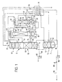
- a first stream or flow of feed vaporous air is introduced through an inlet 2 into a bottom region of a higher pressure rectification column 4, the top of which is thermally linked by a condenser-reboiler 8 to the bottom region of a lower pressure rectification column 6.
- the higher pressure rectification column 4 contains liquid-vapour contact devices 12 in the form of plates, trays or packings. The devices 12 enable an ascending vapour phase to come into intimate contact with a descending liquid phase such that mass transfer takes place between the two phases.
- the ascending vapour is progressively enriched in nitrogen, the most volatile of the three main components (nitrogen, oxygen and argon) of the purified air, the descending liquid is progressively enriched in oxygen, and the least volatile of these three components.
- a second compressed, purified, air stream is introduced into the higher pressure rectification column 4 in liquid state through an inlet 14 which is typically located at a level such that the number of trays or plates or the height of packing therebelow corresponds to a few theoretical trays (for example, about 5).
- a height of packing or a sufficient number of trays or plates is included in the higher pressure rectification column 4 sufficient for an essentially pure nitrogen vapour to flow out of the top of the column 4 into the condenser-reboiler 8 where it is condensed. A part of the resulting condensate is returned to the higher pressure rectification column 4 as reflux.
- a stream of a first oxygen-enriched liquid air fraction is withdrawn from the bottom of the higher pressure rectification column 4 through an outlet 16.
- the oxygen-enriched liquid air stream is sub-cooled by passage through a heat exchanger 18.
- the sub-cooled, oxygen-enriched, liquid air stream is reduced in pressure by passage through a throttling valve 20.
- the resulting fluid stream flows into the sump of an intermediate pressure rectification column 24 through an inlet 26.
- the intermediate pressure rectification column has a reboiler 22 in its sump and includes liquid-vapour contact devices 28 that cause intimate contact between an ascending vapour phase and a descending liquid phase with the result that mass transfer takes place between the two phases. As a result, a second oxygen-enriched liquid air fraction and an oxygen-depleted vapour fraction are formed.
- a sufficient height of packing or number of trays or plates is generally included in the intermediate pressure rectification column 24 for the (oxygen-depleted) vapour at the top of the column to be essentially pure nitrogen.
- This vapour flows into a condenser 30 (hereinafter termed "the second condenser 30") where it is condensed.
- the second condenser 30 A part of the condensate is employed as reflux in the intermediate pressure rectification column 24.
- Another part of the condensate is employed to provide liquid nitrogen reflux for the lower pressure rectification column 6.
- the condenser-reboiler 8 is also so employed.
- a stream of the condensate formed in the condenser-reboiler 8 is sub-cooled by passage through the heat exchanger 18, is reduced in pressure by passage through a throttling valve 32, and is introduced into the top of the lower pressure rectification column 6 through an inlet 34.
- a stream of nitrogen condensate is taken from the second condenser 30, is sub-cooled by passage through the heat exchanger 18, and is reduced in pressure by passage through a throttling valve 36.
- the resulting pressure-reduced liquid nitrogen is mixed with that introduced into the lower pressure column 6 through the inlet 34, the mixing taking place downstream of the throttling valve 32.
- the reboiler 22 forms an ascending vapour stream in operation of the intermediate pressure rectification column 24 by reboiling some of the liquid at the bottom of the column 24.
- the second oxygen-enriched liquid air fraction has an oxygen concentration greater than that of the first oxygen-enriched liquid air. This is because the partial reboiling in the reboiler 22 enriches the liquid in oxygen.
- Further enriched liquid i.e. second oxygen-enriched liquid air fraction
- a first flow of the further-enriched liquid stream passes through a throttling valve 40.
- the resulting liquid air stream passes through condenser 50 (hereinafter termed “the first condenser 50") which is associated with the top of a side column 52 in which an argon-oxygen stream withdrawn from the lower pressure rectification column 6 is separated.
- the concentration of argon in the argon-oxygen stream is greater than the normal concentration of argon in air.
- the first flow of further-enriched liquid is essentially entirely vaporised in the condenser 50.
- the resulting stream (termed “the first stream of oxygen-enriched vapour”) is introduced into the lower pressure rectification column 6 through an inlet 46 at what shall be referred to below as the second intermediate region of the lower pressure rectification column 6.
- a stream of an intermediate liquid air fraction is withdrawn from the intermediate pressure rectification column 24 through an outlet 42 at an intermediate region thereof.
- a stream of a further intermediate liquid air fraction is withdrawn through an outlet 44 from the same level of the higher pressure rectification column 4 as that at which the inlet 14 is located, and is passed through the heat exchanger 18, thereby being sub-cooled.
- the resulting sub-cooled liquid air stream flows through a throttling valve 48, thereby being reduced in pressure, and is introduced into the intermediate pressure rectification column 24 through an inlet 54 which is at the same level as the outlet 42.
- the stream of the intermediate liquid air fraction flows from the intermediate pressure rectification column through a pressure reducing or expansion valve 56 and is mixed with a second flow of the further enriched liquid downstream of another expansion valve 60 through which the further enriched liquid is passed.
- the resulting stream of oxygen-enriched liquid air is employed to provide refrigeration to the second condenser 30, passing through boiling passages (not shown) thereof, thus effecting condensation of nitrogen vapour therein, and as a result being at least partially and preferably essentially entirely reboiled.
- the resulting vapour (“the second stream of oxygen-enriched vapour”) flows from the second condenser 30 and is introduced into the lower pressure rectification column 6 through an inlet 58 located at an intermediate region ("the third intermediate region") of the lower pressure rectification column 6.
- a flow of vaporous feed air (not enriched in or depleted of oxygen) is introduced into the lower pressure rectification column 6 through an inlet 62 at a level below that of the inlet 34 but above that of the inlet 58.
- this flow of vaporous feed air may be premixed with the second stream of oxygen-enriched vapour.
- the various streams containing oxygen and nitrogen that are introduced into the lower pressure rectification column 6 are separated therein to form, in its sump, oxygen, preferably containing less than 0.5% by volume of impurities, (more preferably less than 0.1% of impurities) and a nitrogen product at its top containing less than 0.1% by volume of impurities.
- the separation is effected by contact of an ascending vapour phase with descending liquid on liquid-vapour contact devices 64, which are preferably packing (typically structured packing), but which alternatively can be provided by trays or plates.
- the ascending vapour is created by boiling liquid oxygen in the boiling passages (not shown) of the reboiler-condenser 8 in indirect heat exchange with condensing nitrogen.
- An oxygen product in liquid state is withdrawn from the bottom of the rectification column through an outlet 66 by a pump 68. Additionally, an oxygen product may be withdrawn in vapour state through another outlet (not shown).
- a gaseous nitrogen product is withdrawn from the top of the rectification column 6 through an outlet 70 and is passed through the heat exchanger 18 in countercurrent heat exchange with the streams being sub-cooled.
- a local maximum of argon is created in a section of the lower pressure rectification column 6 extending from an outlet 74 (which is located at an intermediate region of the column 6, referred to below as the first intermediate region to the intermediate inlet 46.
- An argon-enriched vapour stream is withdrawn through the outlet 74 and is fed into the bottom of the side rectification column 52 through an inlet 76.
- An argon product is separated from the argon-enriched oxygen vapour stream, which stream typically contains from 6 to 14% by volume of argon, in the side column 52.
- the column 52 contains liquid-vapour contact devices 78 in order to effect intimate contact, and hence mass transfer, between ascending vapour and descending liquid.
- the descending liquid is created by operation of the condenser 50 to condense argon taken from the top of the column 52.
- a part of the condensate is returned to the top of the column 52 as reflux; another part is withdrawn through an outlet 80 as liquid argon product.
- the liquid-vapour contact devices 78 may comprise structured or random packing, typically a low pressure drop structured packing, or trays or plates in order to effect the separation.
- low pressure drop packing is usually employed so as to ensure that the pressure at the top of the side column 52 is such that the condensing temperature of the argon exceeds the temperature of the fluid which is used to cool the condenser 50.
- a stream of vaporous mixture of argon and oxygen is withdrawn through an outlet 81 from an intermediate region of the side rectification column 52 from 5 to 10 theoretical stages above the bottom thereof and is used to heat the reboiler 22 associated with the intermediate pressure rectification column 24.
- the stream of the vaporous mixture is condensed in part or entirely, and is returned to the column 52 through an inlet 83.
- An impure liquid oxygen stream is withdrawn from the bottom of the side rectification column 52 through an outlet 82 and is passed through an inlet 84 to the same region of the low pressure rectification column 6 as that from which the argon-enriched oxygen vapour stream is withdrawn through the outlet 74.
- an elevated pressure nitrogen product may be taken from the nitrogen condensed in the reboiler-condenser 8 by means of a pump 86.
- a part of the elevated pressure liquid nitrogen stream may be taken from a pipe 88 and vaporised, typically in indirect heat exchange with incoming air streams.
- Another part of the elevated pressure liquid nitrogen stream may be taken via a conduit 90 as a liquid nitrogen product.
- an elevated pressure oxygen gaseous product may be created by vaporisation of part of the liquid oxygen stream withdrawn by the pump 68. The remaining part of the oxygen may be taken as a liquid product.
- each of the streams that is reduced in pressure by passage through a valve may be sub-cooled upstream of the valve.
- the lower pressure rectification column 6 operates at a pressure about 1.4 bar at its top; the higher pressure rectification column 4 operates at a pressure about 5.5 bar at its top; the side rectification column 52 operates at a pressure of 1.3 bar at its top; and the intermediate pressure rectification column 24 operates at a pressure of approximately 2.7 bar at its top.
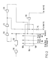
- FIG. 2 there is shown another part of the air separation plant which is employed to form the air streams employed in that part of the plant shown in Figure 1.
- an air stream is compressed in a first compressor 100.
- the compressor 100 has an aftercooler (not shown) associated therewith so as to remove the heat of compression from the compressed air.
- the air stream is passed through a purification unit 102 effective to remove water vapour and carbon dioxide therefrom.
- the unit 102 employs beds (not shown) of adsorbent to effect this removal of water vapour and carbon dioxide. If desired, hydrocarbons may also be removed in the unit 102.
- the beds of the unit 102 are operated out of sequence with one another such that while one or more beds are purifying the compressed air stream, the remainder are able to be regenerated, for example, by being purged by a stream of hot nitrogen.
- Such purification units and their operation are well known and need not be described further.
- the purified air stream is divided into two subsidiary streams.
- a first subsidiary stream of purified air flows through a main heat exchanger 104 from its warm end 106 to its cold end 108 and is cooled to approximately its dew point.
- the resulting cooled vaporous air stream forms a part of the air stream which is introduced into the higher pressure rectification column 4 through the inlet 2 in that part of the plant which is shown in Figure 1.
- the second subsidiary stream of purified compressed air is further compressed in a first booster-compressor 110 having an aftercooler (not shown) associated therewith to remove the heat of compression.
- the further compressed air stream is compressed yet again in a second booster-compressor 112. It is again cooled in an aftercooler (not shown) to remove heat of compression.
- Downstream of this aftercooler one part of the yet further compressed air is passed into the main heat exchanger 104 from its warm end 106.
- the air flows through the main heat exchanger and is withdrawn from its cold end 108.
- This air stream is, downstream of the cold end 108, passed through a throttling or pressure reduction valve 114 and exits the valve 114 predominantly in liquid state.
- This liquid air stream forms the liquid stream which is introduced into the higher pressure rectification column 104 through the inlet 114 (see Figure 1).
- a first expansion turbine 116 is fed with a stream of the yet further compressed air withdrawn from an intermediate location of the main heat exchanger 104.
- the air is expanded in the turbine 116 with the performance of external work and the resulting air leaves the turbine 116 at approximately its saturation temperature and at the same pressure as that at which the first subsidiary air stream leaves the cold end of the main heat exchanger 104.
- the air from the expansion turbine 116 is supplied to the inlet 62 to the lower pressure rectification column 6 (see Figure 1).
- a further part of the yet further compressed air is taken from upstream of the warm end 106 of the main heat exchanger 104 and is expanded with the performance of external work in a second expansion turbine 120.
- This air stream is introduced into the first subsidiary stream of air as it passes through the main heat exchanger 104.
- the gaseous nitrogen product stream which is taken from the heat exchanger 18 (see Figure 1 ) is warmed to ambient temperature by passage through the heat exchanger 104.
- the pressure of the air stream that is liquefied and the pressures of the liquid nitrogen and the liquid oxygen streams are selected so as to maintain thermodynamically efficient operation of the heat exchanger 104.
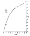
- FIG 3 illustrates the operation of the lower pressure rectification column 6 shown in Figure 1 when the vaporous feed air that is introduced into the lower pressure rectification column does not flow through the inlet 62 but is premixed with the second oxygen-enriched vapour.
- the inlet 62 is instead employed to introduce a stream of liquid air into the lower pressure rectification column 6. This stream of liquid air may form part of the feed air which is liquefied or may be taken from the stream which is withdrawn from the higher pressure rectification column 4 through the outlet 44.
- the curve AB is the equilibrium line for operation of the lower pressure rectification column 6.
- the curve CC'DEFG is its operating line. Point F is at the first, Point E is at the second, and Point D is at the third intermediate region of the column 6. (It is the mixture of the second oxygen-enriched vapour and the vaporous feed air that is introduced at point D.)
- Point C' is at the inlet 62 for liquid air.
- the Point F is at a vapour phase mole fraction of oxygen of about 0.45 (i.e. about 45% by volume) and the Point D is at a vapour phase mole fraction of oxygen of about 0.25 (i.e. about 25% by volume).
- Points D and E a single pinch typically at a vapour phase mole fraction of oxygen of about 0.35 (i.e. about 35% by volume).
- the slope of the operating line below the single pinch is not as great with the result that less vapour can be fed to the side column. Accordingly, the apparatus shown in Figure 1 makes possible an increased liquid/vapour ratio in the region EF with the advantages mentioned hereinabove.
- the method according to the invention permits exceptional flexibility in the taking of liquid products from the column system while still obtaining good argon recovery.
- gaseous oxygen is produced at a rate of 22,000 Nm 3 /hr, the recovery of oxygen being over 99% and the argon recovery being 94-8%. Notwithstanding these high recoveries, liquid nitrogen is taken at approximately 7,500 Nm 3 /hr.
- Such a combination of production rates and recoveries is not possible from a comparable conventional plant which does not include an intermediate pressure rectification column or from a comparable plant in which the reboiler associated with the intermediate pressure rectification column is heated by nitrogen.
- a gaseous oxygen product is produced at a rate of 22,000 Nm 3 /hr
- a medium pressure gaseous nitrogen product is taken from the higher pressure rectification column 4 at a rate of 9,000 Nm 3 /hr
- a liquid nitrogen product is taken at a rate of 1,200 Nm 3 /hr
- vaporous feed air is fed directly from an expansion turbine into the lower pressure rectification column 6 at a rate of 14,000 Nm 3 /hr.
- the oxygen recovery is 98.9% and the argon recovery is 57%. These are substantially higher recoveries than those which can be achieved when a conventional plant, or a plant in which the reboiler associated with the intermediate pressure rectification column is heated by nitrogen, is operated with the same flow rates.
- the reboiler-condenser 8 could be of the downflow rather than the thermosiphon kind.
- the condensers 30 and 50 instead of being of a straight-through or downflow reboiler kind may be of a thermosiphon kind.
- the second flow of the further-enriched liquid and the intermediate stream of liquid air are separately vaporised in the second condenser 30 and the resulting vapour streams mixed to form the second oxygen-enriched vapour.
- a stream of liquid feed air, or a stream of liquid typically containing from 15 to 30% by volume of oxygen is withdrawn from the lower pressure rectification column or the higher pressure rectification column, and is mixed with the second flow of the further-enriched liquid air.
Applications Claiming Priority (2)
| Application Number | Priority Date | Filing Date | Title |
|---|---|---|---|
| GB9618577 | 1996-09-05 | ||
| GBGB9618577.2A GB9618577D0 (en) | 1996-09-05 | 1996-09-05 | Air separation |
Publications (3)
| Publication Number | Publication Date |
|---|---|
| EP0828123A2 true EP0828123A2 (fr) | 1998-03-11 |
| EP0828123A3 EP0828123A3 (fr) | 1998-06-17 |
| EP0828123B1 EP0828123B1 (fr) | 2002-11-13 |
Family
ID=10799492
Family Applications (1)
| Application Number | Title | Priority Date | Filing Date |
|---|---|---|---|
| EP97306450A Expired - Lifetime EP0828123B1 (fr) | 1996-09-05 | 1997-08-22 | Séparation d'air |
Country Status (4)
| Country | Link |
|---|---|
| US (1) | US5862680A (fr) |
| EP (1) | EP0828123B1 (fr) |
| DE (1) | DE69717031D1 (fr) |
| GB (1) | GB9618577D0 (fr) |
Cited By (1)
| Publication number | Priority date | Publication date | Assignee | Title |
|---|---|---|---|---|
| EP2597409A1 (fr) | 2011-11-24 | 2013-05-29 | L'AIR LIQUIDE, Société Anonyme pour l'Etude et l'Exploitation des Procédés Georges Claude | Processus et appareil pour la séparation de l'air par distillation cryogénique |
Families Citing this family (4)
| Publication number | Priority date | Publication date | Assignee | Title |
|---|---|---|---|---|
| US20240035741A1 (en) | 2022-07-28 | 2024-02-01 | Neil M. Prosser | Air separation unit and method for cryogenic separation of air using a distillation column system including an intermediate pressure kettle column |
| US20240035744A1 (en) | 2022-07-28 | 2024-02-01 | Neil M. Prosser | Air separation unit and method for production of nitrogen and argon using a distillation column system with an intermediate pressure kettle column |
| US20240035745A1 (en) | 2022-07-28 | 2024-02-01 | Neil M. Prosser | System and method for cryogenic air separation using four distillation columns including an intermediate pressure column |
| US11959701B2 (en) | 2022-07-28 | 2024-04-16 | Praxair Technology, Inc. | Air separation unit and method for production of high purity nitrogen product using a distillation column system with an intermediate pressure kettle column |
Citations (5)
| Publication number | Priority date | Publication date | Assignee | Title |
|---|---|---|---|---|
| US4533375A (en) * | 1983-08-12 | 1985-08-06 | Erickson Donald C | Cryogenic air separation with cold argon recycle |
| EP0633438A1 (fr) * | 1993-07-05 | 1995-01-11 | The BOC Group plc | Séparation de l'air |
| EP0694745A1 (fr) * | 1994-07-25 | 1996-01-31 | The BOC Group plc | Séparation de l'air |
| EP0717249A2 (fr) * | 1994-12-16 | 1996-06-19 | The BOC Group plc | Séparation d'air |
| EP0733869A2 (fr) * | 1995-03-21 | 1996-09-25 | The BOC Group plc | Séparation d'air |
Family Cites Families (3)
| Publication number | Priority date | Publication date | Assignee | Title |
|---|---|---|---|---|
| FR2689224B1 (fr) * | 1992-03-24 | 1994-05-06 | Lair Liquide | Procede et installation de production d'azote sous haute pression et d'oxygene. |
| FR2700205B1 (fr) * | 1993-01-05 | 1995-02-10 | Air Liquide | Procédé et installation de production d'au moins un produit gazeux sous pression et d'au moins un liquide par distillation d'air. |
| US5471842A (en) * | 1994-08-17 | 1995-12-05 | The Boc Group, Inc. | Cryogenic rectification method and apparatus |
-
1996
- 1996-09-05 GB GBGB9618577.2A patent/GB9618577D0/en active Pending
-
1997
- 1997-08-22 EP EP97306450A patent/EP0828123B1/fr not_active Expired - Lifetime
- 1997-08-22 DE DE69717031T patent/DE69717031D1/de not_active Expired - Lifetime
- 1997-09-05 US US08/925,810 patent/US5862680A/en not_active Expired - Fee Related
Patent Citations (5)
| Publication number | Priority date | Publication date | Assignee | Title |
|---|---|---|---|---|
| US4533375A (en) * | 1983-08-12 | 1985-08-06 | Erickson Donald C | Cryogenic air separation with cold argon recycle |
| EP0633438A1 (fr) * | 1993-07-05 | 1995-01-11 | The BOC Group plc | Séparation de l'air |
| EP0694745A1 (fr) * | 1994-07-25 | 1996-01-31 | The BOC Group plc | Séparation de l'air |
| EP0717249A2 (fr) * | 1994-12-16 | 1996-06-19 | The BOC Group plc | Séparation d'air |
| EP0733869A2 (fr) * | 1995-03-21 | 1996-09-25 | The BOC Group plc | Séparation d'air |
Cited By (2)
| Publication number | Priority date | Publication date | Assignee | Title |
|---|---|---|---|---|
| EP2597409A1 (fr) | 2011-11-24 | 2013-05-29 | L'AIR LIQUIDE, Société Anonyme pour l'Etude et l'Exploitation des Procédés Georges Claude | Processus et appareil pour la séparation de l'air par distillation cryogénique |
| WO2013075867A1 (fr) | 2011-11-24 | 2013-05-30 | L'air Liquide, Societe Anonyme Pour L'etude Et L'exploitation Des Procedes Georges Claude | Procédé et dispositif pour séparer de l'air par distillation cryogénique |
Also Published As
| Publication number | Publication date |
|---|---|
| DE69717031D1 (de) | 2002-12-19 |
| EP0828123A3 (fr) | 1998-06-17 |
| US5862680A (en) | 1999-01-26 |
| EP0828123B1 (fr) | 2002-11-13 |
| GB9618577D0 (en) | 1996-10-16 |
Similar Documents
| Publication | Publication Date | Title |
|---|---|---|
| US5533339A (en) | Air separation | |
| EP0636845B1 (fr) | Séparation d'air | |
| EP0684438B1 (fr) | Séparation de l'air | |
| EP0733869B1 (fr) | Séparation d'air | |
| EP0694745B2 (fr) | Séparation de l'air | |
| EP0577349B1 (fr) | Séparation d'air | |
| US5582031A (en) | Air separation | |
| EP0881446B1 (fr) | Procédé cryogénique avec double colonne et condenseur-reboilleur externe pour liquide riche | |
| US5893276A (en) | Air separation | |
| EP0770841B1 (fr) | Séparation d'air | |
| EP0752565B1 (fr) | Production d'argon | |
| EP0752566B1 (fr) | Séparation d'air | |
| US5689975A (en) | Air separation | |
| US5878598A (en) | Air separation | |
| US5868007A (en) | Air separation | |
| EP0828124B1 (fr) | Séparation d'air | |
| US6089041A (en) | Air separation | |
| EP0828123B1 (fr) | Séparation d'air | |
| EP0831284B1 (fr) | Séparation d'air |
Legal Events
| Date | Code | Title | Description |
|---|---|---|---|
| PUAI | Public reference made under article 153(3) epc to a published international application that has entered the european phase |
Free format text: ORIGINAL CODE: 0009012 |
|
| AK | Designated contracting states |
Kind code of ref document: A2 Designated state(s): BE DE FR GB IT NL |
|
| PUAL | Search report despatched |
Free format text: ORIGINAL CODE: 0009013 |
|
| AK | Designated contracting states |
Kind code of ref document: A3 Designated state(s): AT BE CH DE DK ES FI FR GB GR IE IT LI LU MC NL PT SE |
|
| 17P | Request for examination filed |
Effective date: 19981209 |
|
| AKX | Designation fees paid |
Free format text: BE DE FR GB IT NL |
|
| RBV | Designated contracting states (corrected) |
Designated state(s): BE DE FR GB IT NL |
|
| 17Q | First examination report despatched |
Effective date: 20000828 |
|
| GRAG | Despatch of communication of intention to grant |
Free format text: ORIGINAL CODE: EPIDOS AGRA |
|
| GRAG | Despatch of communication of intention to grant |
Free format text: ORIGINAL CODE: EPIDOS AGRA |
|
| GRAG | Despatch of communication of intention to grant |
Free format text: ORIGINAL CODE: EPIDOS AGRA |
|
| GRAH | Despatch of communication of intention to grant a patent |
Free format text: ORIGINAL CODE: EPIDOS IGRA |
|
| GRAH | Despatch of communication of intention to grant a patent |
Free format text: ORIGINAL CODE: EPIDOS IGRA |
|
| GRAA | (expected) grant |
Free format text: ORIGINAL CODE: 0009210 |
|
| AK | Designated contracting states |
Kind code of ref document: B1 Designated state(s): BE DE FR GB IT NL |
|
| PG25 | Lapsed in a contracting state [announced via postgrant information from national office to epo] |
Ref country code: NL Free format text: LAPSE BECAUSE OF FAILURE TO SUBMIT A TRANSLATION OF THE DESCRIPTION OR TO PAY THE FEE WITHIN THE PRESCRIBED TIME-LIMIT Effective date: 20021113 Ref country code: IT Free format text: LAPSE BECAUSE OF FAILURE TO SUBMIT A TRANSLATION OF THE DESCRIPTION OR TO PAY THE FEE WITHIN THE PRESCRIBED TIME-LIMIT;WARNING: LAPSES OF ITALIAN PATENTS WITH EFFECTIVE DATE BEFORE 2007 MAY HAVE OCCURRED AT ANY TIME BEFORE 2007. THE CORRECT EFFECTIVE DATE MAY BE DIFFERENT FROM THE ONE RECORDED. Effective date: 20021113 Ref country code: FR Free format text: LAPSE BECAUSE OF FAILURE TO SUBMIT A TRANSLATION OF THE DESCRIPTION OR TO PAY THE FEE WITHIN THE PRESCRIBED TIME-LIMIT Effective date: 20021113 Ref country code: BE Free format text: LAPSE BECAUSE OF FAILURE TO SUBMIT A TRANSLATION OF THE DESCRIPTION OR TO PAY THE FEE WITHIN THE PRESCRIBED TIME-LIMIT Effective date: 20021113 |
|
| REG | Reference to a national code |
Ref country code: GB Ref legal event code: FG4D |
|
| REF | Corresponds to: |
Ref document number: 69717031 Country of ref document: DE Date of ref document: 20021219 |
|
| PG25 | Lapsed in a contracting state [announced via postgrant information from national office to epo] |
Ref country code: DE Free format text: LAPSE BECAUSE OF FAILURE TO SUBMIT A TRANSLATION OF THE DESCRIPTION OR TO PAY THE FEE WITHIN THE PRESCRIBED TIME-LIMIT Effective date: 20030214 |
|
| NLV1 | Nl: lapsed or annulled due to failure to fulfill the requirements of art. 29p and 29m of the patents act | ||
| PG25 | Lapsed in a contracting state [announced via postgrant information from national office to epo] |
Ref country code: GB Free format text: LAPSE BECAUSE OF NON-PAYMENT OF DUE FEES Effective date: 20030822 |
|
| EN | Fr: translation not filed | ||
| PLBE | No opposition filed within time limit |
Free format text: ORIGINAL CODE: 0009261 |
|
| STAA | Information on the status of an ep patent application or granted ep patent |
Free format text: STATUS: NO OPPOSITION FILED WITHIN TIME LIMIT |
|
| 26N | No opposition filed |
Effective date: 20030814 |
|
| GBPC | Gb: european patent ceased through non-payment of renewal fee |