EP0827835B1 - Supply system for solid ink jet ink - Google Patents
Supply system for solid ink jet ink Download PDFInfo
- Publication number
- EP0827835B1 EP0827835B1 EP97306759A EP97306759A EP0827835B1 EP 0827835 B1 EP0827835 B1 EP 0827835B1 EP 97306759 A EP97306759 A EP 97306759A EP 97306759 A EP97306759 A EP 97306759A EP 0827835 B1 EP0827835 B1 EP 0827835B1
- Authority
- EP
- European Patent Office
- Prior art keywords
- ink
- ink stick
- supply system
- endless belt
- stick
- Prior art date
- Legal status (The legal status is an assumption and is not a legal conclusion. Google has not performed a legal analysis and makes no representation as to the accuracy of the status listed.)
- Expired - Lifetime
Links
- 239000007787 solid Substances 0.000 title claims description 68
- 238000000034 method Methods 0.000 claims description 20
- 238000012546 transfer Methods 0.000 claims description 6
- 239000000976 ink Substances 0.000 description 206
- 230000009471 action Effects 0.000 description 11
- 230000008859 change Effects 0.000 description 7
- 239000012071 phase Substances 0.000 description 7
- 238000007639 printing Methods 0.000 description 6
- 239000007791 liquid phase Substances 0.000 description 4
- 230000005484 gravity Effects 0.000 description 3
- 239000007788 liquid Substances 0.000 description 3
- 238000005452 bending Methods 0.000 description 2
- 230000008901 benefit Effects 0.000 description 2
- RDYMFSUJUZBWLH-UHFFFAOYSA-N endosulfan Chemical compound C12COS(=O)OCC2C2(Cl)C(Cl)=C(Cl)C1(Cl)C2(Cl)Cl RDYMFSUJUZBWLH-UHFFFAOYSA-N 0.000 description 2
- 239000012943 hotmelt Substances 0.000 description 2
- 230000003287 optical effect Effects 0.000 description 2
- 239000008188 pellet Substances 0.000 description 2
- 230000002093 peripheral effect Effects 0.000 description 2
- 230000000717 retained effect Effects 0.000 description 2
- 239000003086 colorant Substances 0.000 description 1
- 238000013461 design Methods 0.000 description 1
- 238000011161 development Methods 0.000 description 1
- 238000001125 extrusion Methods 0.000 description 1
- 238000007641 inkjet printing Methods 0.000 description 1
- 230000007246 mechanism Effects 0.000 description 1
- 239000000155 melt Substances 0.000 description 1
- 238000012986 modification Methods 0.000 description 1
- 230000004048 modification Effects 0.000 description 1
- 230000001681 protective effect Effects 0.000 description 1
- 238000010926 purge Methods 0.000 description 1
- 230000000153 supplemental effect Effects 0.000 description 1
Images





Classifications
-
- B—PERFORMING OPERATIONS; TRANSPORTING
- B41—PRINTING; LINING MACHINES; TYPEWRITERS; STAMPS
- B41J—TYPEWRITERS; SELECTIVE PRINTING MECHANISMS, i.e. MECHANISMS PRINTING OTHERWISE THAN FROM A FORME; CORRECTION OF TYPOGRAPHICAL ERRORS
- B41J2/00—Typewriters or selective printing mechanisms characterised by the printing or marking process for which they are designed
- B41J2/005—Typewriters or selective printing mechanisms characterised by the printing or marking process for which they are designed characterised by bringing liquid or particles selectively into contact with a printing material
- B41J2/01—Ink jet
- B41J2/17—Ink jet characterised by ink handling
- B41J2/175—Ink supply systems ; Circuit parts therefor
- B41J2/17593—Supplying ink in a solid state
Definitions
- This invention relates generally to supplying solid ink sticks to an ink jet printer and, more specifically, to a color ink stick supply system and related method for continuously supplying ink sticks to a phase change or solid ink color printer.
- the supply system stores multiple ink sticks in a housing and transfers the ink sticks to a conveyor means for delivery to a print head reservoir.
- the related method provides a simple and efficient loading procedure that assures proper orientation of the ink sticks in the housing.
- Phase change inks are solid at ambient temperatures and liquid at the elevated operating temperatures of an ink jet printing device. Phase change ink is conveniently stored, transported and introduced into an ink jet printer assembly in a solid form. Prior to printing, the ink is heated to a suitable liquid phase temperature. During printer operation, liquid phase ink is supplied to the print head at the proper temperature for ejection.
- Color ink jet printers typically use at least one reservoir corresponding to each different color. Separate ink jets communicate with each reservoir for printing the various ink colors.
- An important consideration in the design of phase change ink jet printers is providing a substantially continuous supply of liquid ink at the ink jet print head from solid ink supply means.
- phase change ink color printers are now being utilized to print on wide format (E-size) media of various types. These wide-format printers consume much larger quantities of ink per print as compared to the prior art solid ink printers for standard-sized media. Accordingly, this development has emphasized the need for a large capacity ink stick supply system that provides a substantially continuous ink flow with a minimum of operator refilling requirements and mechanical failures.
- the system include provisions to prevent the individual ink sticks from adhering to adjacent surfaces in the supply system or to one another. It is also desirable to provide a simple and efficient procedure for loading a large number of multi-colored ink sticks into the supply system. The loading procedure and the supply system should cooperate to assure that the correct ink color is provided to the appropriate print head reservoir.
- Patent Abstracts of Japan, vol. 9, no. 297 (M-432), 25 November 1985 & JP 60 135260 A (NIPPON DENSHIN DENWA KOSHA), 18 July 1985 describes an ink jet printer comprising a feed apparatus having extrusion arms adapted to press each solid ink stick always tot he inside of a nozzle.
- a pusher rod and a conveyor means having a stop device for retaining an ink stick are not disclosed.
- EP 0 519 700 A2 describes a method and apparatus for supplying phase change ink stick to an ink jet printer.
- a pusher rod in the supply channel and a conveyor means having a stop device for retaining an ink stick is not disclosed.
- the solid ink stick supply system positively transfers individual ink sticks to a conveyor means for delivery to the print head.
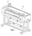
- FIG. 1 of the drawings shows an overall view of a wide format solid ink color printer 10 that incorporates the solid ink supply system of the present invention, generally represented by the reference numeral 12.
- the wide format color printer 10 includes an ink jet print head that utilizes a plurality of inks having different color characteristics.
- the ink jet print head includes a reservoir for each color where the solid ink sticks are melted to the liquid phase by heaters and the liquified ink is delivered to the print head to permit jetting in the heated liquid phase.
- An example of this type of print head is disclosed in U.S. Patent No.
- the ink supply system 12 of the present invention is comprised of a housing, generally represented by the reference numeral 14, that receives and stores solid ink sticks 16 (only one of which is shown in Figure 2).
- the housing 14 contains a keyed plate 20 that includes a plurality of bottomless receptacles 22A-D.
- Each of the bottomless receptacles 22A-D corresponds in shape to a distinctive ink stick shape.
- the commonly-shaped bottomless receptacles 22A-D are arranged in rows with each row positioned above a separate supply channel.
- Figure 2 shows a side view in partial cross section of the row of bottomless receptacles 22A and a supply channel 24 below.
- bottomless receptacles 22B-D and the supply channels and related components associated therewith are structurally and functionally equivalent to the bottomless receptacle row 22A, supply channel 24 and related components now described. Accordingly, the following descriptions are applicable to these other rows and associated supply channels and components as well.
- the solid ink stick supply system of the present invention includes a simple and efficient method for loading multiple ink sticks to refill the system.
- Figure 4 shows an ink stick 16d being inserted into a bottomless receptacle 22A.
- each of the bottomless receptacles 22A defines a bottomless receptacle for receipt of an ink stick.
- Opposing side walls 70, 72 in the bottomless receptacle 22A guide the ink stick 16d as it travels downwardly toward the supply channel 24 below.
- Ink sticks 16a-c have been previously inserted and are being supported by a contacting means in the supply channel 24.
- the contacting means comprises a pusher rod 26 that slides on a bottom surface 82 of the supply channel 24.
- the housing 14 is inclined elevationally upwardly so that a base end 62 of the supply channel 24 is elevationally higher than a delivery end 64 of the channel, whereby the pusher rod 26 tends to slide downwardly toward the delivery end 64 of the channel.
- a bottommost portion 74 of the ink stick 16d ( Figure 4) contacts an upper surface 27 of the pusher rod 26 ( Figure 5), while a peripheral portion 75 of the ink stick engages at least one of the opposing side walls 70, 72 of the bottomless receptacle 22A.
- the ink stick 16d is now held in a "ready position” as shown in Figure 5.
- a top portion 78 of the ink stick 16d protrudes from the bottomless receptacle 22A.
- the pusher rod 26 is retracted in the direction of action arrow A.
- this is accomplished by an operator grasping and pulling the pusher rod handle 80, shown in Figure 2, away from the housing 14.
- the pusher rod handle 80 shown in Figure 2
- the ink stick is guided by the opposing side walls 70, 72 of the bottomless receptacle 22A to descend in a controlled manner into the supply channel 24.
- the ink stick Upon reaching the bottom surface 82 of the supply channel 24, the ink stick moves downwardly toward the delivery end 64 of the channel until it contacts either a previously loaded ink stick, as illustrated by adjacent ink sticks 16a and 16b in Figure 5, or the adjacent endless belt, as illustrated by ink stick 16.
- the operator allows the pusher rod 26 to slide downwardly in the channel until the pushing surface 29 on the rod positively engages the rearmost ink stick in the channel, as shown in Figure 6.
- the pusher rod 26 positively transfers the ink sticks remaining in the supply channel 24 toward the delivery end 64 of the channel.
- the lateral force imparted on the remaining ink sticks by the pusher rod 26 prevents the ink sticks from adhering to an adjacent surface in the supply channel 24, and potentially tipping and thereby jamming or interrupting the ink stick supply.
- the rod is automatically positioned under a bottomless receptacle 22A and ready for supplemental ink stick loading.
- each ink stick is properly oriented in each supply channel for transfer to an adjacent endless belt. More specifically, as shown in Figure 5, the bottommost portion 74 of each ink stick must be substantially flush with the bottom surface 82 of the supply channel 24. Adjacent ink sticks in the supply channel must also be in mated peripheral alignment, as illustrated by ink sticks 16, 16a and 16b in Figure 5.
- the required orientation is achieved by aligning the ink sticks with the bottomless receptacles 22A-D in the keyed plate 20 as shown in Figure 3.
- the opposing side walls 70, 72 of the bottomless receptacle are given a height that is at least 25% of the length of the ink stick. Additionally, the distance between the upper surface 27 of the pusher rod 26 and the upper ends 31, 33 of the side walls 70, 72 is at least 50% of the length of the ink stick.
- the housing 14 includes means for detecting a low ink condition.
- a low ink condition is defined as two or less ink sticks available for delivery to the print head reservoir 28.
- the detecting means comprises a tab 66 that extends downwardly from the pusher rod 26 and through a slot (not shown) in the supply channel 24.
- the pusher rod 26 advances downwardly in the supply channel 24 such that a protruding tongue 67 on tab 66 engages and pivots a low ink trip lever 68.
- the low ink trip lever 68 operates in conjunction with an optical sensor (not shown) to signal the low ink condition by illuminating an indicator light on a status panel 11 on the printer 10, as shown in Figure 1.
- an optical sensor not shown
- the low ink trip lever 68 returns by spring biasing (not shown) to its initial position shown in Figure 6.
- the preferred embodiment of the present invention also includes a pivotable cover plate 84 to enclose the keyed plate 20 and the supply channels 24 when the loading of ink sticks is completed. Additionally, as shown by action arrow D, the keyed plate 20 is preferably slidable within the housing 14 to allow an operator to gain access to the supply channels 24 below to clear any ink stick jams or misfeeds.
- the present invention utilizes conveyer means and means for driving the conveyor means to deliver color solid ink sticks to a corresponding ink jet print head reservoir of the same color.
- the preferred conveyor means comprises a plurality of endless belts 30, with each endless belt being adjacent to one of the supply channels 24, as best seen in Figure 6.
- the driving means preferably includes a drive pulley 32 and a driven pulley 34 that engage the inner surface 36 of the belt 30.
- the inner surface 36 of the endless belt 30 is given a toothed profile (not shown) that mates with the periphery of the drive and driven pulleys 32, 34.
- a gear 38 is adjacent to the drive pulley 32 and shares a common axis of rotation with the drive pulley.
- the gear 38 is driven by a power source to rotate the drive pulley 32, which in turn advances the endless belt 30.
- the power source comprises a 12 volt DC motor 40 and a worm 42 that engages the gear 38 as shown.
- the endless belt 30 includes a first push device 44 that positively engages and delivers an individual ink stick to the print head reservoir 28.
- the first push device 44 extends from the outer surface 46 of the belt 30.
- the motor 40 is activated to rotate the worm 42 in the direction of action arrow A.
- the worm 42 rotates the gear 38 (not shown), which by a common axis rotates the drive pulley 32 in the direction of action arrow B.
- An ink side track 35 of the endless belt 30 is then advanced in the direction of action arrow C such that the first push device 44 engages the ink stick 16b and positively moves the ink stick into the reservoir 28.
- the ink stick 16b prior to and during the delivery sequence the ink stick 16b is in contact with an adjacent ink stick 16c in the supply channel 24. Over time, and in the heat of the printing environment, the two ink sticks 16b, 16c may adhere to one another along their common surface. Any such adherence will oppose the movement of ink stick 16b into the reservoir 28, and potentially could cause a jam or misfeed at the endless belt 30.
- the first push device 44 substantially avoids this potential problem by affirmatively separating the two ink sticks 16b, 16c and positively pushing ink stick 16b until it leaves the endless belt 30 and enters the reservoir 28.
- the weight of ink sticks 16b-d and pusher rod 26 tends to deflect the ink side track 35 of the endless belt 30 inwardly and increase the load on the drive and driven pulleys 32, 34. Additionally, as explained above, any adherence between adjacent ink sticks 16b, 16c will oppose the movement of ink stick 16b. As the first push device 44 engages the ink stick 16b, this adherence creates a bending force at the point of attachment of the push device 44 to the endless belt 30.
- a flange 48 is provided adjacent to the inner surface 36 of the ink side track 35 at the location where the ink sticks contact the belt 30.
- the flange 48 prevents the belt 30 from deflecting excessively and counteracts the bending force on push device 44 during the delivery of an ink stick.
- the endless belt 30 further includes a first stop device 58 that retains an ink stick on the endless belt 30 prior to its delivery to the print head reservoir 28.
- the first stop device 58 is spaced from the first push device 44 such that at the end of a delivery sequence the stop device is positioned substantially parallel with the bottom surface 82 of the supply channel 24, as illustrated in Figure 7. In this manner, after the ink stick 16b is delivered to the print head reservoir 28, the next ink stick 16c is transferred from the supply channel 24 to the endless belt 30 and is retained by the first stop device 58 from entering the print head reservoir 28.
- a second push device 44' and a second stop device 58' are provided on the endless belt 30.
- the second push and stop devices 44', 58' are substantially equidistant from the first push and stop devices 44, 58, respectively, along the circumference of the belt 30.
- the motor 40 will be activated by the printer firmware (not shown) to advance the endless belt 30, whereby the push device 44' will contact and deliver ink stick 16c to the reservoir 28 and push device 44 will engage the contact 60 at the completion of the delivery.
- an alternative embodiment of the present invention includes support means for supporting a second ink stick 16c above the ink side track 35 of the endless belt 30 while a first ink stick 16b is delivered to the print head reservoir 28.
- the support means comprises a plurality of tabs 45 extending from the outer surface 46 of the belt 30.
- the motor 40 is activated to rotate the worm 42 in the direction of action arrow A.
- the worm 42 rotates the gear 38 (not shown), which by a common axis rotates the drive pulley 32 in the direction of action arrow B.
- the ink side track 35 of the endless belt 30 is then advanced in a first direction, as indicated by action arrow C, such that the first push device 44 engages the ink stick 16b and positively moves the ink stick into the reservoir 28, while the tabs 45 move adjacent to the periphery 75 of the ink stick 16c.
- the tabs 45 also engage and close the contact 60, which in turn signals the printer firmware (not shown) that a delivery sequence is in progress.
- ink stick 16b moves into the print head reservoir 28, ink stick 16c is transferred against the tabs 45 and is thereby spaced from the ink side track 35 of the belt 30.
- the contact 60 opens to signal the printer firmware that the delivery of ink stick 16b to the reservoir 28 is completed.
- the printer firmware stops the motor 40 and then reverses the motor to rotate the worm 42 in the direction of action arrow D.
- Drive pulley 32 rotates in the direction of action arrow E which in turn advances the ink side track 35 of the endless belt 30 in a second direction indicated by action arrow F.
- ink stick 16c is supported above and away from the ink side track 35 of the belt 30 to reduce the possibility of an ink stick jam.
- the tabs 45 slide along the periphery 75 of the ink stick 16c, the tabs agitate and vibrate both ink sticks 16c and 16d in the supply channel 24. In this manner, the tabs 45 loosen any adherence between the two ink sticks 16c and 16d, as well as any adherence between the ink sticks and an adjacent surface of the supply channel 24, to facilitate a smooth transfer to the endless belt 30.
- the confirming means comprises a gate, generally represented by the reference numeral 50, and a delivery trip lever 56.
- the gate 50 is biased in a position such that a first arm 52 extends into the path of the ink stick 16c to the print head reservoir 28.
- the ink stick 16b pushes against the first arm 52 to pivot the gate 50 such that a second arm 54 contacts and pivots the delivery trip lever 56.
- the delivery trip lever 56 operates in conjunction with an optical sensor (not shown) to confirm the delivery of the ink stick 16b to the print head reservoir 28.
- the gate 50 After the ink stick 16b has been delivered, the gate 50 returns to its initial position as shown in Figure 7 by spring biasing (not shown). As it will be appreciated, the first arm 52 of the gate 50 also guides an ink stick as it is transferred from the supply channel 24 onto the endless belt 30. In this manner, the gate 50 prevents the ink stick from tipping or misfeeding and possibly causing a jam. The gate 50 also assists the stop devices 58, 58' in preventing a second ink stick from entering the reservoir 28 after the delivery of a first ink stick.
Landscapes
- Ink Jet (AREA)
- Particle Formation And Scattering Control In Inkjet Printers (AREA)
Description
- This invention relates generally to supplying solid ink sticks to an ink jet printer and, more specifically, to a color ink stick supply system and related method for continuously supplying ink sticks to a phase change or solid ink color printer. The supply system stores multiple ink sticks in a housing and transfers the ink sticks to a conveyor means for delivery to a print head reservoir. The related method provides a simple and efficient loading procedure that assures proper orientation of the ink sticks in the housing.
- Ink jet printers typically utilize a variety of inks, including phase change or solid inks, which are sometimes referred to as hot melt inks. Phase change inks are solid at ambient temperatures and liquid at the elevated operating temperatures of an ink jet printing device. Phase change ink is conveniently stored, transported and introduced into an ink jet printer assembly in a solid form. Prior to printing, the ink is heated to a suitable liquid phase temperature. During printer operation, liquid phase ink is supplied to the print head at the proper temperature for ejection.
- Color ink jet printers typically use at least one reservoir corresponding to each different color. Separate ink jets communicate with each reservoir for printing the various ink colors. An important consideration in the design of phase change ink jet printers is providing a substantially continuous supply of liquid ink at the ink jet print head from solid ink supply means.
- Early solid ink jet printers used pellets of colored cyan, yellow, magenta and black ink that were loaded into shape coded openings. The openings fed the pellets generally vertically and downwardly by gravity into the heater assembly of the printer where they entered separate reservoirs corresponding to each color. In each reservoir the ink sticks were melted into a liquid state for jetting onto the receiving medium. Other prior art solid ink jet printers used a flexible web of hot melt ink that was incrementally unwound and advanced to a heater location, or vibratory delivery of particulate solid ink to the melt chamber.
- Later more successful solid ink printers, such as the Tektronix Phaser® III, the Tektronix Phaser® 300, and the Jolt printer offered by Dataproducts Corporation, used differently shaped solid ink sticks that were either passively fed by gravity or spring loaded into a feed chute. Other ink stick loading systems have utilized a horizontal feed tray in which individual ink sticks are stored end-to-end. The ink sticks are advanced in the feed tray until they fall by gravity through an aperture into a print head reservoir.
- While generally adequate for their intended purposes, the prior art solid ink supply systems have a relatively limited ink stick storage capacity and are typically mechanically complex. Additionally, phase change ink color printers are now being utilized to print on wide format (E-size) media of various types. These wide-format printers consume much larger quantities of ink per print as compared to the prior art solid ink printers for standard-sized media. Accordingly, this development has emphasized the need for a large capacity ink stick supply system that provides a substantially continuous ink flow with a minimum of operator refilling requirements and mechanical failures. To assure continuous and unrestricted delivery of ink sticks to the printer, and to reduce costly down time, it is desirable that the system include provisions to prevent the individual ink sticks from adhering to adjacent surfaces in the supply system or to one another. It is also desirable to provide a simple and efficient procedure for loading a large number of multi-colored ink sticks into the supply system. The loading procedure and the supply system should cooperate to assure that the correct ink color is provided to the appropriate print head reservoir.
- Patent Abstracts of Japan, vol. 9, no. 297 (M-432), 25 November 1985 & JP 60 135260 A (NIPPON DENSHIN DENWA KOSHA), 18 July 1985 describes an ink jet printer comprising a feed apparatus having extrusion arms adapted to press each solid ink stick always tot he inside of a nozzle. A pusher rod and a conveyor means having a stop device for retaining an ink stick are not disclosed.
- EP 0 519 700 A2 describes a method and apparatus for supplying phase change ink stick to an ink jet printer. A pusher rod in the supply channel and a conveyor means having a stop device for retaining an ink stick is not disclosed.
- It is an object of the present invention to provide an ink stick supply system for a solid ink printer that includes a large storage capacity for delivering a substantially continuous supply of ink sticks to a print head reservoir for printing.
- It is another object of the present invention to provide an ink stick supply system that utilizes a mechanically simple ink stick delivery mechanism that operates effectively and reliably in a solid ink printing environment.
- It is another object of the present invention to provide an ink stick supply system that avoids jamming by preventing ink sticks from adhering to adjacent surfaces or to one another.
- It is yet another object of the present invention to provide an ink stick supply system that positively delivers individual ink sticks to the print head reservoir.
- The foregoing objects are achieved by providing a solid ink stick supply system according to claim 1 and a method for delivering a solid ink stick according to
claim 31. - It is a feature of the present invention that the procedure for loading ink sticks into the supply system is efficient and assures that the ink sticks are properly oriented and delivered to the correct reservoir.
- It is another feature of the present invention that the solid ink stick supply system positively transfers individual ink sticks to a conveyor means for delivery to the print head.
- It is an advantage of the present invention that the solid ink stick supply system and loading procedure permit only the correctly colored ink stick to be fed into the appropriate supply channel for that color.
- It is another advantage of the present invention that only properly oriented ink sticks are fed into the supply channel to reduce the possibility of jamming.
- Still other aspects of the present invention will become apparent to those skilled in this art from the following description wherein there is shown and described a preferred embodiment of this invention, simply by way of illustration of one of the modes best suited to carry out the invention. As it will be realized, the invention is capable of other different embodiments and its several details are capable of modifications in various, obvious aspects all without departing from the invention. Accordingly, the drawings and descriptions will be regarded as illustrative in nature and not as restrictive. And now for a brief description of the drawings.
- The following description is intended to illustrate the invention, by way of example only, reference being made to the accompanying drawings in which:-
- Figure 1 is an overall perspective view showing a solid ink color printer that is particularly adapted for printing on wide format media and utilizes the solid ink supply system of the present invention.
- Figure 2 is a side elevational view in partial cross section of the solid ink supply system showing a pusher rod fully extended into a supply channel and a single ink stick positioned on an endless belt.
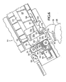
- Figure 3 is a top elevational view taken along the lines 3-3 of Figure 2 showing a keyed plate positioned in a housing and a cover pivoted open.
- Figure 4 is a side elevational view in partial cross section showing an ink stick being inserted into a bottomless receptacle in the keyed plate.
- Figure 5 is a side elevational view in partial cross section showing a pusher rod being retracted in a supply channel during a loading procedure.
- Figure 6 is a side elevational view in partial cross section showing a first push device on an endless belt engaging an ink stick and delivering the ink stick to a print head reservoir.
- Figure 7 is a side elevational view in partial cross section showing the endless belt in a stationary, post-delivery position with a first stop device retaining an ink stick on the belt.
- Figure 8 is an enlarged side view in partial cross section of the endless belt showing a drive and a driven pulley engaging the endless belt and a worm engaging a gear.
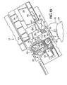
- Figure 9 is an enlarged partial top view taken along the lines 9-9 of Figure 8 showing side-by-side endless belts, each belt being adjacent to a gear that is driven by a worm.
- Figure 10 is a side elevational view in partial cross section of an alternative embodiment of the present invention showing a first push device on an endless belt engaging an ink stick and a plurality of tabs extending from the belt.
- Figure 11 is a side elevational view in partial cross section of the alternative embodiment showing the endless belt advancing in a second direction and the tabs on the endless belt supporting an ink stick.
-
- Reference will now be made in detail to the present preferred embodiment of the invention, an example of which is illustrated in the accompanying drawings.
- Reference is now made to Figure 1 of the drawings which shows an overall view of a wide format solid
ink color printer 10 that incorporates the solid ink supply system of the present invention, generally represented by thereference numeral 12. The wideformat color printer 10 includes an ink jet print head that utilizes a plurality of inks having different color characteristics. The ink jet print head includes a reservoir for each color where the solid ink sticks are melted to the liquid phase by heaters and the liquified ink is delivered to the print head to permit jetting in the heated liquid phase. An example of this type of print head is disclosed in U.S. Patent No. 5,455,615 for a MULTIPLE-ORIFICE DROP-ON-DEMAND INK JET PRINT HEAD HAVING IMPROVED PURGING AND JETTING PERFORMANCE, assigned to the assignee of this application. It should be noted that the ink supply system of the present invention is also suitable for use with other types of ink jet printers, other ink jet print heads and with inks having distinctive properties other than color. - With reference now to Figures 2 and 3, the
ink supply system 12 of the present invention is comprised of a housing, generally represented by thereference numeral 14, that receives and stores solid ink sticks 16 (only one of which is shown in Figure 2). As best seen in Figure 3, thehousing 14 contains akeyed plate 20 that includes a plurality ofbottomless receptacles 22A-D. Each of thebottomless receptacles 22A-D corresponds in shape to a distinctive ink stick shape. The commonly-shapedbottomless receptacles 22A-D are arranged in rows with each row positioned above a separate supply channel. Figure 2 shows a side view in partial cross section of the row ofbottomless receptacles 22A and asupply channel 24 below. It will be understood that the other rows of bottomless receptacles 22B-D and the supply channels and related components associated therewith are structurally and functionally equivalent to thebottomless receptacle row 22A,supply channel 24 and related components now described. Accordingly, the following descriptions are applicable to these other rows and associated supply channels and components as well. - With reference now to Figures 4 and 5, the solid ink stick supply system of the present invention includes a simple and efficient method for loading multiple ink sticks to refill the system. Figure 4 shows an
ink stick 16d being inserted into abottomless receptacle 22A. As this Figure illustrates, each of thebottomless receptacles 22A defines a bottomless receptacle for receipt of an ink stick. Opposingside walls bottomless receptacle 22A guide theink stick 16d as it travels downwardly toward thesupply channel 24 below. Ink sticks 16a-c have been previously inserted and are being supported by a contacting means in thesupply channel 24. In the preferred embodiment of the present invention, the contacting means comprises apusher rod 26 that slides on abottom surface 82 of thesupply channel 24. As best illustrated in Figure 2, thehousing 14 is inclined elevationally upwardly so that abase end 62 of thesupply channel 24 is elevationally higher than adelivery end 64 of the channel, whereby thepusher rod 26 tends to slide downwardly toward thedelivery end 64 of the channel. - Referring again to Figures 4 and 5, as the
ink stick 16d continues to move downwardly into thesupply channel 24, abottommost portion 74 of theink stick 16d (Figure 4) contacts anupper surface 27 of the pusher rod 26 (Figure 5), while aperipheral portion 75 of the ink stick engages at least one of the opposingside walls bottomless receptacle 22A. Theink stick 16d is now held in a "ready position" as shown in Figure 5. Preferably, in this "ready position" atop portion 78 of theink stick 16d protrudes from thebottomless receptacle 22A. Advantageously, this prevents an operator from inserting a second ink stick into that bottomless receptacle and potentially causing a jam or misfeed. - As illustrated in Figure 5, when a desired number of ink sticks have been inserted into the bottomless receptacles, the
pusher rod 26 is retracted in the direction of action arrow A. Preferably, this is accomplished by an operator grasping and pulling thepusher rod handle 80, shown in Figure 2, away from thehousing 14. As acontact surface 29 of thepusher rod 26 passes from beneath eachink stick 16a-d, the ink stick is guided by the opposingside walls bottomless receptacle 22A to descend in a controlled manner into thesupply channel 24. Upon reaching thebottom surface 82 of thesupply channel 24, the ink stick moves downwardly toward thedelivery end 64 of the channel until it contacts either a previously loaded ink stick, as illustrated by adjacent ink sticks 16a and 16b in Figure 5, or the adjacent endless belt, as illustrated byink stick 16. - After the desired number of ink sticks have been loaded into the
supply channel 24, the operator allows thepusher rod 26 to slide downwardly in the channel until the pushingsurface 29 on the rod positively engages the rearmost ink stick in the channel, as shown in Figure 6. With reference now generally to Figures 6 and 7, as ink sticks are delivered one-by-one to theprint head reservoir 28, thepusher rod 26 positively transfers the ink sticks remaining in thesupply channel 24 toward thedelivery end 64 of the channel. Advantageously, the lateral force imparted on the remaining ink sticks by thepusher rod 26 prevents the ink sticks from adhering to an adjacent surface in thesupply channel 24, and potentially tipping and thereby jamming or interrupting the ink stick supply. Additionally, as thepusher rod 26 advances down thesupply channel 24 with the delivery of each ink stick, the rod is automatically positioned under abottomless receptacle 22A and ready for supplemental ink stick loading. - With reference now only to the preferred embodiment of the present invention, it is important that the ink sticks are properly oriented in each supply channel for transfer to an adjacent endless belt. More specifically, as shown in Figure 5, the
bottommost portion 74 of each ink stick must be substantially flush with thebottom surface 82 of thesupply channel 24. Adjacent ink sticks in the supply channel must also be in mated peripheral alignment, as illustrated by ink sticks 16, 16a and 16b in Figure 5. - Initially, the required orientation is achieved by aligning the ink sticks with the
bottomless receptacles 22A-D in thekeyed plate 20 as shown in Figure 3. - With reference now to Figure 4, to maintain this orientation as an ink stick travels from a
bottomless receptacle 22A into asupply channel 24, the opposingside walls upper surface 27 of thepusher rod 26 and the upper ends 31, 33 of theside walls side walls bottomless receptacle 22A such that the ink stick maintains its initial orientation and descends in a controlled manner into the supply channel below. - With reference now to Figures 6 and 7, the
housing 14 includes means for detecting a low ink condition. For the purposes of the following discussion only, a low ink condition is defined as two or less ink sticks available for delivery to theprint head reservoir 28. In the preferred embodiment of the present invention, the detecting means comprises atab 66 that extends downwardly from thepusher rod 26 and through a slot (not shown) in thesupply channel 24. As illustrated in Figures 6 and 7, upon delivery of theink stick 16b to theprint head reservoir 28, thepusher rod 26 advances downwardly in thesupply channel 24 such that a protrudingtongue 67 ontab 66 engages and pivots a lowink trip lever 68. The lowink trip lever 68 operates in conjunction with an optical sensor (not shown) to signal the low ink condition by illuminating an indicator light on astatus panel 11 on theprinter 10, as shown in Figure 1. When thepusher rod 26 is retracted upon loading additional ink sticks into thesupply channel 24, the lowink trip lever 68 returns by spring biasing (not shown) to its initial position shown in Figure 6. - With reference now to Figure 3, the preferred embodiment of the present invention also includes a
pivotable cover plate 84 to enclose thekeyed plate 20 and thesupply channels 24 when the loading of ink sticks is completed. Additionally, as shown by action arrow D, thekeyed plate 20 is preferably slidable within thehousing 14 to allow an operator to gain access to thesupply channels 24 below to clear any ink stick jams or misfeeds. - The present invention utilizes conveyer means and means for driving the conveyor means to deliver color solid ink sticks to a corresponding ink jet print head reservoir of the same color. As shown in Figures 3, 6 and 9, the preferred conveyor means comprises a plurality of
endless belts 30, with each endless belt being adjacent to one of thesupply channels 24, as best seen in Figure 6. For eachendless belt 30, the driving means preferably includes adrive pulley 32 and a drivenpulley 34 that engage theinner surface 36 of thebelt 30. To insure accurate movement of the belt without slippage, theinner surface 36 of theendless belt 30 is given a toothed profile (not shown) that mates with the periphery of the drive and drivenpulleys gear 38 is adjacent to the drivepulley 32 and shares a common axis of rotation with the drive pulley. Thegear 38 is driven by a power source to rotate thedrive pulley 32, which in turn advances theendless belt 30. Preferably, the power source comprises a 12volt DC motor 40 and aworm 42 that engages thegear 38 as shown. - In an important aspect of the present invention, the
endless belt 30 includes afirst push device 44 that positively engages and delivers an individual ink stick to theprint head reservoir 28. As shown in Figure 8, thefirst push device 44 extends from theouter surface 46 of thebelt 30. With reference now to Figure 6, during a delivery sequence theprint head reservoir 28 is moved to a loading position adjacent to one end of theendless belt 30 and theprotective cover 39 of the reservoir is pivoted open by a rack and pinion actuator (not shown). Themotor 40 is activated to rotate theworm 42 in the direction of action arrow A. Theworm 42 rotates the gear 38 (not shown), which by a common axis rotates thedrive pulley 32 in the direction of action arrow B. Anink side track 35 of theendless belt 30 is then advanced in the direction of action arrow C such that thefirst push device 44 engages theink stick 16b and positively moves the ink stick into thereservoir 28. - As shown in Figure 6, prior to and during the delivery sequence the
ink stick 16b is in contact with anadjacent ink stick 16c in thesupply channel 24. Over time, and in the heat of the printing environment, the twoink sticks ink stick 16b into thereservoir 28, and potentially could cause a jam or misfeed at theendless belt 30. Advantageously, thefirst push device 44 substantially avoids this potential problem by affirmatively separating the twoink sticks ink stick 16b until it leaves theendless belt 30 and enters thereservoir 28. - With continued reference to Figure 6, the weight of ink sticks 16b-d and
pusher rod 26 tends to deflect theink side track 35 of theendless belt 30 inwardly and increase the load on the drive and drivenpulleys ink stick 16b. As thefirst push device 44 engages theink stick 16b, this adherence creates a bending force at the point of attachment of thepush device 44 to theendless belt 30. To support theink side track 35 of thebelt 30 between the drive and drivenpulleys flange 48 is provided adjacent to theinner surface 36 of theink side track 35 at the location where the ink sticks contact thebelt 30. Advantageously, theflange 48 prevents thebelt 30 from deflecting excessively and counteracts the bending force onpush device 44 during the delivery of an ink stick. - With reference now to Figure 7, the
endless belt 30 further includes afirst stop device 58 that retains an ink stick on theendless belt 30 prior to its delivery to theprint head reservoir 28. Thefirst stop device 58 is spaced from thefirst push device 44 such that at the end of a delivery sequence the stop device is positioned substantially parallel with thebottom surface 82 of thesupply channel 24, as illustrated in Figure 7. In this manner, after theink stick 16b is delivered to theprint head reservoir 28, thenext ink stick 16c is transferred from thesupply channel 24 to theendless belt 30 and is retained by thefirst stop device 58 from entering theprint head reservoir 28. - With continued reference to Figure 7, in the preferred embodiment a second push device 44' and a second stop device 58' are provided on the
endless belt 30. Preferably, the second push and stop devices 44', 58' are substantially equidistant from the first push and stopdevices belt 30. Upon delivery of theink stick 16b (not shown) to theprint head reservoir 28 by thefirst push device 44, the second push device 44' engages acontact 60 to stop themotor 40 and halt the advancement of theendless belt 30. In the next delivery sequence, themotor 40 will be activated by the printer firmware (not shown) to advance theendless belt 30, whereby the push device 44' will contact and deliverink stick 16c to thereservoir 28 andpush device 44 will engage thecontact 60 at the completion of the delivery. - With reference now to Figures 10 and 11, an alternative embodiment of the present invention includes support means for supporting a
second ink stick 16c above theink side track 35 of theendless belt 30 while afirst ink stick 16b is delivered to theprint head reservoir 28. Preferably, the support means comprises a plurality oftabs 45 extending from theouter surface 46 of thebelt 30. As shown in Figure 10, during a delivery sequence themotor 40 is activated to rotate theworm 42 in the direction of action arrow A. Theworm 42 rotates the gear 38 (not shown), which by a common axis rotates thedrive pulley 32 in the direction of action arrow B. Theink side track 35 of theendless belt 30 is then advanced in a first direction, as indicated by action arrow C, such that thefirst push device 44 engages theink stick 16b and positively moves the ink stick into thereservoir 28, while thetabs 45 move adjacent to theperiphery 75 of theink stick 16c. Thetabs 45 also engage and close thecontact 60, which in turn signals the printer firmware (not shown) that a delivery sequence is in progress. - With reference now to Figure 11, as
ink stick 16b (not shown) moves into theprint head reservoir 28,ink stick 16c is transferred against thetabs 45 and is thereby spaced from theink side track 35 of thebelt 30. After the rearmost tab 45' passes thecontact 60, thecontact 60 opens to signal the printer firmware that the delivery ofink stick 16b to thereservoir 28 is completed. At this point, the printer firmware stops themotor 40 and then reverses the motor to rotate theworm 42 in the direction of action arrowD. Drive pulley 32 rotates in the direction of action arrow E which in turn advances theink side track 35 of theendless belt 30 in a second direction indicated by action arrow F. As thebelt 30 advances in this manner, thetabs 45 will slide along theperiphery 75 of theink stick 16c and will closecontact 60. Once thefirst push device 44 passes thetop portion 78 of theink stick 16c, theink stick 16c is fully transferred to theendless belt 30. Shortly thereafter, contact 60 opens within thegap 61 between thefirst push device 44 and thefrontmost tab 45" to halt the advancement of thebelt 30, and theink stick 16c is retained on the belt by thefirst stop device 58 in the same manner as shown in Figure 7. - Advantageously, during the delivery of
ink stick 16b to thereservoir 28,ink stick 16c is supported above and away from theink side track 35 of thebelt 30 to reduce the possibility of an ink stick jam. Additionally, as thetabs 45 slide along theperiphery 75 of theink stick 16c, the tabs agitate and vibrate both ink sticks 16c and 16d in thesupply channel 24. In this manner, thetabs 45 loosen any adherence between the twoink sticks supply channel 24, to facilitate a smooth transfer to theendless belt 30. - With reference now to Figure 6, a means for confirming the delivery of an ink stick to the
print head reservoir 28 is also provided. In the preferred embodiment, the confirming means comprises a gate, generally represented by thereference numeral 50, and adelivery trip lever 56. As best seen in Figure 7, thegate 50 is biased in a position such that afirst arm 52 extends into the path of theink stick 16c to theprint head reservoir 28. With reference now to Figure 6, during a delivery sequence theink stick 16b pushes against thefirst arm 52 to pivot thegate 50 such that asecond arm 54 contacts and pivots thedelivery trip lever 56. Thedelivery trip lever 56 operates in conjunction with an optical sensor (not shown) to confirm the delivery of theink stick 16b to theprint head reservoir 28. After theink stick 16b has been delivered, thegate 50 returns to its initial position as shown in Figure 7 by spring biasing (not shown). As it will be appreciated, thefirst arm 52 of thegate 50 also guides an ink stick as it is transferred from thesupply channel 24 onto theendless belt 30. In this manner, thegate 50 prevents the ink stick from tipping or misfeeding and possibly causing a jam. Thegate 50 also assists thestop devices 58, 58' in preventing a second ink stick from entering thereservoir 28 after the delivery of a first ink stick.
Claims (38)
- A solid ink supply system (12) for feeding solid ink sticks (16A-16D) to an ink jet print head reservoir (28), comprising:characterized bya housing (14) for receiving and storing the solid ink sticks;at least one supply channel (24) within the housing (14);conveyor means (30) adjacent to the housing (14) for delivering an ink stick to the print head reservoir (28), the conveyor means (30) including a first push device (44) for moving the ink stick to the print head reservoir (28); andmeans (40,42) for driving the conveyor means (30) to deliver the ink stick to the print head reservoir (28),
a pusher rod (26) in the supply channel (24) for transferring a solid ink stick from the supply channel to the conveyor means (30); and
the conveyor means (30) further comprising a first stop device (58) for retaining an ink stick. - The solid ink supply system of claim 1, wherein the conveyor means comprises an endless belt (30) having an outer surface (46) and an inner surface (36).
- The solid ink supply system of claim 2, wherein the first push device (44) extends from the outer surface (46) of the belt (30) and engages an ink stick to deliver the ink stick to the print head reservoir (28).
- The solid ink supply system of claim 2 or 3, wherein the first stop device (58) extends from the outer surface (46) of the belt (30) and is spaced from the first push device (44), the first stop device retaining an ink stick on the endless belt (30) to prevent the ink stick from entering the reservoir (28).
- The solid ink stick system of claim 4, wherein the driving means (40,42) drives the endless belt such that an ink side track (35) of the belt (30) moves toward the print head reservoir (28) when the print head reservoir is in a loading position.
- The solid ink supply system of claim 5, wherein the endless belt (30) includes a second push device (44) and a second stop device (58), the second push and stop devices being substantially equidistant from the first push and stop devices, respectfully, along the circumference of the belt (30).
- The solid ink supply system of claim 6, further including a flange (48) adjacent to the inner surface (36) of the endless belt (30) for supporting the belt at a location where a solid ink stick contacts the belt.
- The solid ink supply system of claim 2, wherein the means for driving the endless belt includes a drive pulley (32) and a driven pulley (34) that engage the inner surface (36) of the belt, the driven pulley (34) being spaced from the drive pulley (32).
- The solid ink supply system of claim 8, wherein the means for driving further includes a gear (38) having a common axis of rotation with the drive pulley (32), the gear being driven by a power source (40), the power source preferably includes a worm (42) that engages the gear.
- The solid ink supply system of any preceding claim, further including a keyed plate (20) adjacent to the supply channel (24), the keyed plate including a bottomless receptacle (22A-22D) for receiving a solid ink stick.
- The solid ink supply system of claim 10, wherein the bottomless receptacle (22A-22D) in the keyed plate (20) is in communication with the supply channel (24).
- The solid ink supply system of claim 10 or 11, wherein the bottomless receptacle in the keyed plate includes opposing side walls (70,72) adapted to guide an ink stick into the supply channel (24).
- The solid ink supply system of claim 12, wherein the solid ink stick (16A-16D) has a predetermined length and the opposing side walls of the bottomless receptacle have a height that is at least 25% of the length of the ink stick.
- The solid ink supply system of claim 12 or 13, wherein the opposing side walls of the bottomless receptacle include an upper end (31,33) and the distance between an upper surface (27) of the pusher rod (26) in the supply channel (24) and the upper end (31,33) of the bottomless receptacle is at least 50% of the length of the ink stick.
- The solid ink supply system of any one of claims 10 to 14, wherein the bottomless receptacle is oriented to accept only an ink stick having a predetermined orientation.
- The solid ink supply system of any one of claims 10 to 15, wherein the keyed plate (20) includes a plurality of bottomless receptacles for receiving solid ink sticks having a plurality of distinctive shapes, each of the bottomless receptacles having a shape that corresponds to one of the plurality of distinctive ink stick shapes.
- The solid ink supply system of any one of claims 10 to 16, wherein each of the plurality of bottomless receptacles (22A-22D) having the same shape has the same orientation.
- The solid ink supply system of any one of claims 10 to 17, wherein the housing (14) includes a pivotable cover (84) adapted to enclose the keyed plate (20) and supply channel (24).
- The solid ink supply system of any one of claims 10 to 18, wherein the keyed plate (20) is slidably received within the housing.
- The solid ink supply system of any preceding claim, wherein the housing includes a plurality of supply channels that correspond in number to the plurality of different ink sticks shapes.
- The solid ink supply system of any preceding claim, wherein the pusher rod (26) comprises a pusher rod.
- The solid ink supply system of claim 21, wherein the housing includes a delivery end (64) adjacent to the conveyor means (30) and a base end (62), and the housing is inclined elevationally upwardly so that the base end is elevationally higher than the delivery end, whereby the pusher rod moves toward the delivery end of the housing, the pusher rod having a pushing surface (29) to positively engage an ink stick (16A-16D) in the supply channel (24) and urge the ink stick toward the delivery end (64) of the housing.
- The solid ink supply system of any preceding claim, further including means (66-68) for detecting a low ink condition.
- The solid ink supply system of claim 23, wherein the supply channel (24) includes an elongated slot and the pusher rod includes a tab (66) that extends through the slot and engages the detecting means (68) when a low ink condition occurs.
- The solid ink supply system of any preceding claim, further including means (54-56) for confirming the delivery of an ink stick to the print head reservoir (28).
- The solid ink supply system of claim 20, further comprising a plurality of pusher rods corresponding in number to the plurality of supply channels, each pusher rod being located in one of the supply channels.
- The solid ink supply system of any preceding claim, further including support means for supporting a second ink stick during and after the delivery of a first ink stick to the print head reservoir.
- The solid ink supply system of claim 27, wherein the support means supports the second ink stick by contacting a periphery of the second ink stick.
- The solid ink supply system of claim 28, wherein the conveyor (30) means comprises an endless belt having an outer surface and an inner surface, and the support means comprises a plurality of tabs (45) extending from the outer surface (46) of the endless belt.
- The solid ink supply system of claim 29, wherein the driving means (32,34,40,42) drives the endless belt in a first direction to deliver the first ink stick to the print head reservoir (28), and in a second direction until the plurality of tabs (45) no longer support the second ink stick.
- A method for delivering a solid ink stick (16A-16D) to an ink jet print head reservoir (28), the method comprising the steps of:characterized in thatproviding a supply channel (24) for holding a first ink stick prior to delivery;providing an endless belt (30) adjacent to and in communication with the supply channel (24);positioning the printed reservoir (28) adjacent to one end of the endless belt (30);transferring the first ink stick from the supply channel onto the endless belt (30); anddriving the endless belt to deliver the first ink stick to the print head reservoir (28)
the endless belt (30) includes a push device (44) that engages and moves the first ink stick (16A) to the print head reservoir (28) during the step of driving the endless belt and
the endless belt (30) includes a stop device (58) that retains a second ink stick (16C) on the belt (3) as the first ink stick enters the print head reservoir (28), the stop device (58) preventing the second ink stick from also entering the print head reservoir (28). - The method of claim 31, further including the step of supporting the endless belt at a location where the ink stick contacts the belt.
- The method of any one of claims 31 to 32, further including the step of confirming the delivery of the first ink stick onto the print head reservoir.
- The method of any one of claims 31 to 33, wherein the step of transferring the first ink stick from the supply channel onto the endless belt includes the steps of:providing a pusher rod (26) in the supply channel (24);positioning the first ink stick (16A) between the pusher rod (26) and the endless belt (30); andadvancing the pusher rod to engage the first ink stick and transfer the ink stick to the endless belt.
- The method of any one of claims 31 to 34, further including the step of supporting a second ink stick during and after the delivery of the first ink stick to the print head reservoir.
- The method of claim 35, wherein the step of driving the endless belt (30) comprises driving the endless belt in a first direction to deliver the first ink stick to the print head reservoir, and driving the endless belt in a second direction to allow the second ink stick to be transferred onto the belt.
- The method of claim 36, wherein the step of supporting the second ink stick includes supporting the second ink stick while the endless belt is driven in the second direction.
- The method of claim 37, further including the step of agitating the second ink stick during the step of driving the endless belt.
Applications Claiming Priority (2)
| Application Number | Priority Date | Filing Date | Title |
|---|---|---|---|
| US708766 | 1996-09-05 | ||
| US08/708,766 US5917528A (en) | 1996-09-05 | 1996-09-05 | Solid ink stick supply apparatus and method |
Publications (3)
| Publication Number | Publication Date |
|---|---|
| EP0827835A2 EP0827835A2 (en) | 1998-03-11 |
| EP0827835A3 EP0827835A3 (en) | 1999-09-01 |
| EP0827835B1 true EP0827835B1 (en) | 2004-02-11 |
Family
ID=24847109
Family Applications (1)
| Application Number | Title | Priority Date | Filing Date |
|---|---|---|---|
| EP97306759A Expired - Lifetime EP0827835B1 (en) | 1996-09-05 | 1997-09-02 | Supply system for solid ink jet ink |
Country Status (4)
| Country | Link |
|---|---|
| US (2) | US5917528A (en) |
| EP (1) | EP0827835B1 (en) |
| JP (1) | JP3189752B2 (en) |
| DE (1) | DE69727524T2 (en) |
Cited By (2)
| Publication number | Priority date | Publication date | Assignee | Title |
|---|---|---|---|---|
| CN101181843B (en) * | 2006-11-07 | 2011-04-13 | 施乐公司 | Multiple ink rod for phase change ink imaging device and its forming method |
| CN103619604A (en) * | 2012-03-09 | 2014-03-05 | 滴利数码科技有限公司 | print head alignment device |
Families Citing this family (57)
| Publication number | Priority date | Publication date | Assignee | Title |
|---|---|---|---|---|
| US6170942B1 (en) * | 1997-07-04 | 2001-01-09 | Brother Kogyo Kabushiki Kaisha | Ink supply device |
| JP4592174B2 (en) | 1999-11-15 | 2010-12-01 | オセ−テクノロジーズ ビーブイ | Ink jet apparatus having ink pellet dispenser |
| EP1101617B1 (en) * | 1999-11-15 | 2006-04-12 | Océ-Technologies B.V. | Ink jet device with dispenser for ink pellets |
| EP1101618B1 (en) * | 1999-11-22 | 2005-11-02 | Océ-Technologies B.V. | Method and system for supplying hot melt ink to a printer |
| JP4444484B2 (en) | 1999-11-22 | 2010-03-31 | オセ−テクノロジーズ・ベー・ヴエー | Method and system for supplying hot melt ink to a printer |
| DE19963802B4 (en) * | 1999-12-30 | 2004-02-05 | Siemens Ag | Process for phase synchronization of optical data center data signals |
| US6874880B2 (en) * | 2002-04-29 | 2005-04-05 | Xerox Corporation | Solid ink stick with identifiable shape |
| US6761443B2 (en) * | 2002-04-29 | 2004-07-13 | Xerox Corporation | Keying feature for solid ink stick |
| US6857732B2 (en) | 2002-04-29 | 2005-02-22 | Xerox Corporation | Visible identification of solid ink stick |
| US6722764B2 (en) * | 2002-04-29 | 2004-04-20 | Xerox Corporation | Feed guidance and identification for ink stick |
| US6739713B2 (en) * | 2002-04-29 | 2004-05-25 | Xerox Corporation | Guide for solid ink stick feed |
| US6561636B1 (en) * | 2002-05-30 | 2003-05-13 | Xerox Corporation | Load and feed apparatus for solid ink |
| US6565200B1 (en) | 2002-05-30 | 2003-05-20 | Xerox Corporation | Load and feed apparatus for solid ink |
| US6709094B2 (en) * | 2002-05-30 | 2004-03-23 | Xerox Corporation | Load and feed apparatus for solid ink |
| US6648435B1 (en) * | 2002-05-30 | 2003-11-18 | Xerox Corporation | Load and feed apparatus for solid ink |
| US6679591B2 (en) * | 2002-05-30 | 2004-01-20 | Xerox Corporation | Load and feed apparatus for solid ink |
| EP1366910B1 (en) * | 2002-05-30 | 2006-06-21 | Xerox Corporation | Load and feed apparatus for solid ink |
| US7104635B2 (en) * | 2002-05-30 | 2006-09-12 | Xerox Corporation | Load and feed apparatus for solid ink |
| US6565201B1 (en) * | 2002-05-30 | 2003-05-20 | Xerox Corporation | Load and feed apparatus for solid ink |
| US7207668B2 (en) * | 2004-03-22 | 2007-04-24 | Xerox Corporation | Ink supply container for high speed solid ink printers |
| US7311376B2 (en) * | 2004-09-22 | 2007-12-25 | Hewlett-Packard Development Company, L.P. | Imaging device and method |
| KR100667324B1 (en) * | 2005-04-28 | 2007-01-12 | 삼성전자주식회사 | Solid ink loading device |
| US7591550B2 (en) | 2005-06-09 | 2009-09-22 | Xerox Corporation | Ink consumption determination |
| US7407276B2 (en) | 2005-06-09 | 2008-08-05 | Xerox Corporation | Ink level sensing |
| US7425061B2 (en) * | 2005-06-09 | 2008-09-16 | Xerox Corporation | Ink consumption determination |
| US7458669B2 (en) * | 2005-06-09 | 2008-12-02 | Xerox Corporation | Ink consumption determination |
| EP1803567A1 (en) * | 2005-12-27 | 2007-07-04 | Nederlandse Organisatie voor toegepast-natuurwetenschappelijk Onderzoek TNO | Material jet system |
| AU2006250675A1 (en) * | 2006-01-18 | 2007-08-02 | Oce-Technologies B.V. | Inkjet printer with cartridge for ink pellets |
| US7780283B2 (en) * | 2006-11-07 | 2010-08-24 | Xerox Corporation | Independent keying and guidance for solid ink sticks |
| US7854501B2 (en) * | 2006-11-07 | 2010-12-21 | Xerox Corporation | Common side insertion keying for phase change ink sticks |
| US7798624B2 (en) | 2006-11-21 | 2010-09-21 | Xerox Corporation | Transport system for solid ink in a printer |
| US7883195B2 (en) * | 2006-11-21 | 2011-02-08 | Xerox Corporation | Solid ink stick features for printer ink transport and method |
| US7794072B2 (en) * | 2006-11-21 | 2010-09-14 | Xerox Corporation | Guide for printer solid ink transport and method |
| US7651210B2 (en) * | 2006-11-21 | 2010-01-26 | Xerox Corporation | Transport system for solid ink for cooperation with melt head in a printer |
| US7976144B2 (en) * | 2006-11-21 | 2011-07-12 | Xerox Corporation | System and method for delivering solid ink sticks to a melting device through a non-linear guide |
| US7762655B2 (en) * | 2006-12-11 | 2010-07-27 | Xerox Corporation | Printer ink delivery system |
| US7878636B2 (en) * | 2006-12-12 | 2011-02-01 | Xerox Corporation | Solid ink stick chute for printer solid ink transport with mating solid ink stick chute |
| US7726798B2 (en) | 2006-12-15 | 2010-06-01 | Xerox Corporation | Printer solid ink transport and method |
| US7798626B2 (en) * | 2007-02-28 | 2010-09-21 | Xerox Corporation | System for loading and feeding solid ink sticks to an ink melter in a phase change ink printer |
| US7819513B2 (en) * | 2007-03-09 | 2010-10-26 | Xerox Corporation | Solid ink stick with multiple axis interlocking |
| US7780284B2 (en) * | 2007-03-09 | 2010-08-24 | Xerox Corporation | Digital solid ink stick identification and recognition |
| US7878641B2 (en) * | 2007-03-09 | 2011-02-01 | Xerox Corporation | Solid ink stick with reversible keying and interlocking features |
| US7798627B2 (en) * | 2007-03-09 | 2010-09-21 | Xerox Corporation | Multi-position interlocking ink stick |
| US7976118B2 (en) * | 2007-10-22 | 2011-07-12 | Xerox Corporation | Transport system for providing a continuous supply of solid ink to a melting assembly in a printer |
| US7883196B2 (en) * | 2007-12-21 | 2011-02-08 | Xerox Corporation | System for delivering solid ink through a feed channel having non-linear sections |
| US7887173B2 (en) | 2008-01-18 | 2011-02-15 | Xerox Corporation | Transport system having multiple moving forces for solid ink delivery in a printer |
| US7883197B2 (en) * | 2008-02-27 | 2011-02-08 | Xerox Corporation | Transport system having single insertion port for solid ink delivery in a printer |
| US8052264B2 (en) * | 2008-03-26 | 2011-11-08 | Xerox Corporation | Melting device for increased production of melted ink in a solid ink printer |
| US8240830B2 (en) * | 2010-03-10 | 2012-08-14 | Xerox Corporation | No spill, feed controlled removable container for delivering pelletized substances |
| US8382269B2 (en) * | 2010-04-13 | 2013-02-26 | Xerox Corporation | System and method that enables a solid ink printer to learn a solid ink stick type |
| US8313182B2 (en) * | 2010-10-06 | 2012-11-20 | Xerox Corporation | Ink loader with ink stick retractor |
| US8511806B2 (en) * | 2010-10-15 | 2013-08-20 | Xerox Corporation | Solid ink loader with pull-out drawer for insertion access |
| US8814336B2 (en) | 2011-12-22 | 2014-08-26 | Xerox Corporation | Solid ink stick configuration |
| CN103419496B (en) * | 2012-05-14 | 2015-12-23 | 珠海纳思达企业管理有限公司 | A kind of printer ink supply system and detection method thereof |
| US8777386B2 (en) | 2012-10-17 | 2014-07-15 | Xerox Corporation | Solid ink stick having identical identifying features on a plurality of edges |
| US8727478B2 (en) | 2012-10-17 | 2014-05-20 | Xerox Corporation | Ink loader having optical sensors to identify solid ink sticks |
| US8807695B1 (en) | 2013-01-30 | 2014-08-19 | Xerox Corporation | System and method for estimating ink usage in an inkjet printer |
Family Cites Families (17)
| Publication number | Priority date | Publication date | Assignee | Title |
|---|---|---|---|---|
| JPS60135260A (en) * | 1983-12-23 | 1985-07-18 | Nippon Telegr & Teleph Corp <Ntt> | Ink jet printer |
| US4667206A (en) * | 1984-10-15 | 1987-05-19 | Deyoung Thomas W | Ink jet apparatus and method of operating the ink jet apparatus wherein phase change ink is supplied in solid-state form |
| CA1252670A (en) * | 1984-10-15 | 1989-04-18 | Thomas W. Deyoung | Ink jet apparatus and method of operating the ink jet apparatus wherein phase change ink is supplied in solid-state form |
| US4609924A (en) * | 1984-10-15 | 1986-09-02 | Exxon Printing Systems, Inc. | Buffer reservoir for ink jet apparatus and method |
| US4636803A (en) * | 1984-10-16 | 1987-01-13 | Exxon Printing Systems, Inc. | System to linearly supply phase change ink jet |
| US4682185A (en) * | 1984-11-08 | 1987-07-21 | Martner John G | Ink jet method and apparatus utilizing a web of hot melt ink |
| US4682187A (en) * | 1984-11-08 | 1987-07-21 | Martner John G | Ink jet method and apparatus utilizing grandular or hot melt ink |
| US4739339A (en) * | 1986-02-14 | 1988-04-19 | Dataproducts Corporation | Cartridge and method of using a cartridge for phase change ink in an ink jet apparatus |
| US5172135A (en) * | 1987-09-09 | 1992-12-15 | Spectra, Inc. | Hot melt ink supply unit |
| US4870430A (en) * | 1987-11-02 | 1989-09-26 | Howtek, Inc. | Solid ink delivery system |
| EP0683051B1 (en) * | 1988-04-22 | 2000-08-09 | Seiko Epson Corporation | Ink jet type recording apparatus and method |
| US5038157A (en) * | 1989-08-18 | 1991-08-06 | Apple Computer, Inc. | Apparatus and method for loading solid ink pellets into a printer |
| US5181049A (en) * | 1989-11-09 | 1993-01-19 | Dataproducts Corporation | Phase change ink replenishment system |
| EP0506403B1 (en) * | 1991-03-25 | 1995-08-23 | Tektronix, Inc. | Method and apparatus for providing phase change ink to an ink jet printer |
| US5223860A (en) * | 1991-06-17 | 1993-06-29 | Tektronix, Inc. | Apparatus for supplying phase change ink to an ink jet printer |
| WO1996014989A2 (en) * | 1994-11-10 | 1996-05-23 | Lasermaster Corporation | Large format ink jet printer and ink supply system |
| US5861903A (en) * | 1996-03-07 | 1999-01-19 | Tektronix, Inc. | Ink feed system |
-
1996
- 1996-09-05 US US08/708,766 patent/US5917528A/en not_active Expired - Lifetime
-
1997
- 1997-01-31 US US08/792,603 patent/US5975690A/en not_active Expired - Lifetime
- 1997-08-28 JP JP23261197A patent/JP3189752B2/en not_active Expired - Fee Related
- 1997-09-02 DE DE69727524T patent/DE69727524T2/en not_active Expired - Lifetime
- 1997-09-02 EP EP97306759A patent/EP0827835B1/en not_active Expired - Lifetime
Cited By (3)
| Publication number | Priority date | Publication date | Assignee | Title |
|---|---|---|---|---|
| CN101181843B (en) * | 2006-11-07 | 2011-04-13 | 施乐公司 | Multiple ink rod for phase change ink imaging device and its forming method |
| CN103619604A (en) * | 2012-03-09 | 2014-03-05 | 滴利数码科技有限公司 | print head alignment device |
| CN103619604B (en) * | 2012-03-09 | 2015-10-07 | 滴利数码科技有限公司 | print head alignment device |
Also Published As
| Publication number | Publication date |
|---|---|
| JPH1086412A (en) | 1998-04-07 |
| DE69727524T2 (en) | 2004-07-01 |
| DE69727524D1 (en) | 2004-03-18 |
| EP0827835A2 (en) | 1998-03-11 |
| US5917528A (en) | 1999-06-29 |
| JP3189752B2 (en) | 2001-07-16 |
| US5975690A (en) | 1999-11-02 |
| EP0827835A3 (en) | 1999-09-01 |
Similar Documents
| Publication | Publication Date | Title |
|---|---|---|
| US5917528A (en) | Solid ink stick supply apparatus and method | |
| EP1925451B1 (en) | Transport system for solid ink in a printer | |
| US7651210B2 (en) | Transport system for solid ink for cooperation with melt head in a printer | |
| EP0820872A2 (en) | Ink pellet | |
| US5861903A (en) | Ink feed system | |
| RU2256560C2 (en) | Printing device | |
| US7883195B2 (en) | Solid ink stick features for printer ink transport and method | |
| US5801725A (en) | Slidable wiping and capping service station for ink jet printer | |
| CN101352976B (en) | Image forming apparatus, image forming method, and image forming system | |
| EP2231412B1 (en) | Selector for engagement of printer functions | |
| EP1925455A2 (en) | Guide for Printer Solid Ink Transport and Method | |
| US20040251592A1 (en) | Sheet media input structure for a sheet media processing device | |
| CN102848743B (en) | Image forming apparatus | |
| US7887173B2 (en) | Transport system having multiple moving forces for solid ink delivery in a printer | |
| US7976144B2 (en) | System and method for delivering solid ink sticks to a melting device through a non-linear guide | |
| US6170942B1 (en) | Ink supply device | |
| JPS6195946A (en) | Ink jet device and method of operating ink jet device | |
| US8240831B2 (en) | System and method for controlling insertion of solid ink sticks into a printer | |
| JP5027004B2 (en) | Solid ink stick loading and supply system | |
| US7416296B2 (en) | Platen plate and liquid discharging device | |
| KR20120039474A (en) | A phase change ink imaging device | |
| EP0820873A2 (en) | Ink supplying apparatus | |
| US6918643B2 (en) | Printer capable of automatically adjusting inkjet clearance for printing on thick, non flexible printing material | |
| JP3915882B2 (en) | Recording medium supply device, supply method, and recording device | |
| JP4453811B2 (en) | Gap adjusting device, recording device, liquid ejecting device |
Legal Events
| Date | Code | Title | Description |
|---|---|---|---|
| PUAI | Public reference made under article 153(3) epc to a published international application that has entered the european phase |
Free format text: ORIGINAL CODE: 0009012 |
|
| AK | Designated contracting states |
Kind code of ref document: A2 Designated state(s): DE FR GB NL |
|
| PUAL | Search report despatched |
Free format text: ORIGINAL CODE: 0009013 |
|
| AK | Designated contracting states |
Kind code of ref document: A3 Designated state(s): AT BE CH DE DK ES FI FR GB GR IE IT LI LU MC NL PT SE |
|
| 17P | Request for examination filed |
Effective date: 20000201 |
|
| AKX | Designation fees paid |
Free format text: DE FR GB NL |
|
| RAP1 | Party data changed (applicant data changed or rights of an application transferred) |
Owner name: XEROX CORPORATION |
|
| 17Q | First examination report despatched |
Effective date: 20021120 |
|
| GRAP | Despatch of communication of intention to grant a patent |
Free format text: ORIGINAL CODE: EPIDOSNIGR1 |
|
| GRAS | Grant fee paid |
Free format text: ORIGINAL CODE: EPIDOSNIGR3 |
|
| GRAA | (expected) grant |
Free format text: ORIGINAL CODE: 0009210 |
|
| AK | Designated contracting states |
Kind code of ref document: B1 Designated state(s): DE FR GB NL |
|
| REG | Reference to a national code |
Ref country code: GB Ref legal event code: FG4D |
|
| REF | Corresponds to: |
Ref document number: 69727524 Country of ref document: DE Date of ref document: 20040318 Kind code of ref document: P |
|
| ET | Fr: translation filed | ||
| PLBE | No opposition filed within time limit |
Free format text: ORIGINAL CODE: 0009261 |
|
| STAA | Information on the status of an ep patent application or granted ep patent |
Free format text: STATUS: NO OPPOSITION FILED WITHIN TIME LIMIT |
|
| 26N | No opposition filed |
Effective date: 20041112 |
|
| PGFP | Annual fee paid to national office [announced via postgrant information from national office to epo] |
Ref country code: GB Payment date: 20060830 Year of fee payment: 10 |
|
| GBPC | Gb: european patent ceased through non-payment of renewal fee |
Effective date: 20070902 |
|
| PG25 | Lapsed in a contracting state [announced via postgrant information from national office to epo] |
Ref country code: GB Free format text: LAPSE BECAUSE OF NON-PAYMENT OF DUE FEES Effective date: 20070902 |
|
| PGFP | Annual fee paid to national office [announced via postgrant information from national office to epo] |
Ref country code: NL Payment date: 20120823 Year of fee payment: 16 |
|
| PGFP | Annual fee paid to national office [announced via postgrant information from national office to epo] |
Ref country code: DE Payment date: 20130820 Year of fee payment: 17 |
|
| PGFP | Annual fee paid to national office [announced via postgrant information from national office to epo] |
Ref country code: FR Payment date: 20130920 Year of fee payment: 17 |
|
| REG | Reference to a national code |
Ref country code: NL Ref legal event code: V1 Effective date: 20140401 |
|
| PG25 | Lapsed in a contracting state [announced via postgrant information from national office to epo] |
Ref country code: NL Free format text: LAPSE BECAUSE OF NON-PAYMENT OF DUE FEES Effective date: 20140401 |
|
| REG | Reference to a national code |
Ref country code: DE Ref legal event code: R119 Ref document number: 69727524 Country of ref document: DE |
|
| REG | Reference to a national code |
Ref country code: FR Ref legal event code: ST Effective date: 20150529 |
|
| PG25 | Lapsed in a contracting state [announced via postgrant information from national office to epo] |
Ref country code: DE Free format text: LAPSE BECAUSE OF NON-PAYMENT OF DUE FEES Effective date: 20150401 |
|
| PG25 | Lapsed in a contracting state [announced via postgrant information from national office to epo] |
Ref country code: FR Free format text: LAPSE BECAUSE OF NON-PAYMENT OF DUE FEES Effective date: 20140930 |