EP0827163B1 - Engine igniting coil device - Google Patents
Engine igniting coil device Download PDFInfo
- Publication number
- EP0827163B1 EP0827163B1 EP97113683A EP97113683A EP0827163B1 EP 0827163 B1 EP0827163 B1 EP 0827163B1 EP 97113683 A EP97113683 A EP 97113683A EP 97113683 A EP97113683 A EP 97113683A EP 0827163 B1 EP0827163 B1 EP 0827163B1
- Authority
- EP
- European Patent Office
- Prior art keywords
- coil
- bobbin
- wound bobbin
- secondary coil
- case
- Prior art date
- Legal status (The legal status is an assumption and is not a legal conclusion. Google has not performed a legal analysis and makes no representation as to the accuracy of the status listed.)
- Expired - Lifetime
Links
- 229920005989 resin Polymers 0.000 claims description 23
- 239000011347 resin Substances 0.000 claims description 23
- 238000009413 insulation Methods 0.000 claims description 11
- 229920001971 elastomer Polymers 0.000 description 8
- 238000005336 cracking Methods 0.000 description 7
- 230000008646 thermal stress Effects 0.000 description 6
- 230000035882 stress Effects 0.000 description 5
- 230000008602 contraction Effects 0.000 description 4
- 238000004804 winding Methods 0.000 description 4
- 230000004907 flux Effects 0.000 description 3
- 239000002184 metal Substances 0.000 description 2
- 238000004382 potting Methods 0.000 description 2
- 238000007789 sealing Methods 0.000 description 2
- 229910000831 Steel Inorganic materials 0.000 description 1
- 239000000853 adhesive Substances 0.000 description 1
- 230000001070 adhesive effect Effects 0.000 description 1
- 238000013016 damping Methods 0.000 description 1
- 230000006866 deterioration Effects 0.000 description 1
- 230000000694 effects Effects 0.000 description 1
- 239000013013 elastic material Substances 0.000 description 1
- 239000000806 elastomer Substances 0.000 description 1
- 239000003822 epoxy resin Substances 0.000 description 1
- -1 i.e. Polymers 0.000 description 1
- 238000002347 injection Methods 0.000 description 1
- 239000007924 injection Substances 0.000 description 1
- 239000007788 liquid Substances 0.000 description 1
- 239000006247 magnetic powder Substances 0.000 description 1
- 239000000463 material Substances 0.000 description 1
- 238000000465 moulding Methods 0.000 description 1
- 230000002093 peripheral effect Effects 0.000 description 1
- 230000035699 permeability Effects 0.000 description 1
- 229920000647 polyepoxide Polymers 0.000 description 1
- 229920001296 polysiloxane Polymers 0.000 description 1
- 239000011148 porous material Substances 0.000 description 1
- 230000035939 shock Effects 0.000 description 1
- 239000007787 solid Substances 0.000 description 1
- 239000010959 steel Substances 0.000 description 1
Images

Classifications
-
- H—ELECTRICITY
- H01—ELECTRIC ELEMENTS
- H01F—MAGNETS; INDUCTANCES; TRANSFORMERS; SELECTION OF MATERIALS FOR THEIR MAGNETIC PROPERTIES
- H01F38/00—Adaptations of transformers or inductances for specific applications or functions
- H01F38/12—Ignition, e.g. for IC engines
-
- H—ELECTRICITY
- H01—ELECTRIC ELEMENTS
- H01F—MAGNETS; INDUCTANCES; TRANSFORMERS; SELECTION OF MATERIALS FOR THEIR MAGNETIC PROPERTIES
- H01F38/00—Adaptations of transformers or inductances for specific applications or functions
- H01F38/12—Ignition, e.g. for IC engines
- H01F2038/122—Ignition, e.g. for IC engines with rod-shaped core
Definitions
- the present invention relates to an open-magnetic-circuit type engine-igniting coil device.
- EP 0 142 175 A2 discloses an open-magnetic-circuit-type engine igniting coil device which has a coil case which contains an assembly integrally molded therein by potting with melted insulating resin and consisting of a primary coil bobbin having a hollow shaft with a rod-shape core and a secondary coil bobbin coaxially laid on the primary coil bobbin and which is further provided at its lower portion with a high-voltage terminal connector to be directly connected with a tip of an ignition plug of the engine.
- the primary coil bobbin can be coaxially mounted into a hollow shaft of the secondary bobbin by abutting at its flange against the inside wall of the hollow shaft of the secondary bobbin.
- the coil assembly can also be coaxially mounted in the coil case by abutting at its flange against the inner wall of the coil case.
- Japanese Utility Model Publication No. 4-23296 also discloses an open-magnetic-circuit-type engine igniting coil device which has a coil case containing a coil assembly integrally molded therein by potting with melt insulating resin and consisting of a primary coil bobbin having a hollow shaft with a rod-shape core and a secondary coil bobbin coaxially fitted on the primary coil bobbin and which is further provided with an ignition-plug connector portion integrally formed on the coil case for direct connection with a ingition plug in such a way that a tip of the ignition plug inserted therein can contact with a high-voltage terminal inwardly projecting in the connector portion of the coil case-.
- an engine igniting coil device directly attached to an ignition plug has a long case to be inserted into a cylinder bore made in a cylinder head of a vehicle engine and said case may therefore have a large amount of thermal elongation and shrinkage of metal, producing a large axial stress in the insulation resin layer formed therein and, in consequence of this, causing cracking of the flanges of primary and secondary coil bobbins.
- the arrangement of the flange of the secondary coil bobbin close to a portion with the high-voltageside terminal of the secondary coil may cause a leak current to flow through the flange to the coil case.
- the present invention provides an engine igniting coil device directly attachable to an ignition plug of an engine, wherein a primary and secondary coil bobbins are flangeless (at least one end of each bobbin) and can be coaxially mounted each other in a coil case, thus eliminating the possibility of damaging the coil bobbins due-to a large axial stress produced by thermal expansion and contraction as well as the possibility of current leakage from the high-voltage portion of the secondary coil bobbin to the coil case.
- the secondary coil bobbin has a protrusion formed at its external wall apart from a high-voltage terminal of the secondary coil wound thereon.
- the secondary coil bobbin has inwardly protruding ribs for coaxially supporting a flangeless end of the primary coil bobbin mounted therein.
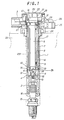
- Fig. 1 is a sectional front view of an engine igniting coil device embodying the present invention.
- Fig. 2 is a plan view showing an internal structure of a low-voltage terminal socket portion of the engine igniting coil device shown in Fig. 1.
- Fig. 3 is a sectional side view of a coil case of the engine igniting coil device shown in Fig. 1.
- Fig. 4 is a sectional front view of a second coil bobbin on which a secondary coil is formed by bank winding with slope winding and which omits a flange at its one end.
- an engine igniting coil device has a coil case 1 for mounting therein a coil assembly, which has a plug cover 2 fitted in its lower open end and a low-voltage terminal socket 3 fitted on its upper open end.
- the coil case 1 accommodates a coil assembly composed of a secondary coil bobbin 8 with a secondary coil 7, a primary coil bobbin 6 with a primary coil 5 inserted in a hollow shaft of the secondary coil bobbin and a rod-shape core inserted in a hollow shaft of the primary coil bobbin.
- the core 9 is provided at each end with a permanent magnet 10 for obtaining a large change in magnetic flux with an interrupted primary current.
- a high-voltage terminal holder 11 is a center projection formed integrally with the lower end portion of the secondary coil bobbin 8.
- a high-voltage terminal 12 bonded to the holder 11 has a spring contact 13 attached thereto for providing electrical connection with an ignition plug 15.
- the coil assembly composed of the primary coil bobbin 6, secondary coil bobbin 8, high-voltage terminal 12 and contact 13 is mounted in a given position and fixed in the coil case in such a manner that a holder portion 11 of the high-voltage terminal 12 is press-fitted in a tubular hole 4 made in a center potion of the coil case 1 and the spring contact 13 outwardly projected from the tubular hole 4.
- the coil case 1 with the assembly fixed in the given position therein is filled with melted insulating resin (e.g., epoxy resin) injected through an upper open-end of the coil case 1 to form a single solid device with solidified resin insulation therein.
- melted insulating resin e.g., epoxy resin
- the permanent magnets 10 attached one to each end of the core 9 are covered with damping members 14, respectively, which can prevent intrusion of melted resin into the core 9 and absorb a relatively large thermal stress produced in the longitudinal direction of the core 9, thus preventing cracking of the resin layer formed round the core 9.
- the plug cover 2 is provided at its top end with a plug rubber 16 for holding the ignition plug 15.
- a tip of the ignition plug 15 comes into contact with the spring contact 13, making an electrical connection of the ignition coil device.
- the low-voltage terminal socket 3 contains an igniter 19 as shown in Fig. 2.
- the low-voltage terminal socket 3 is fitted on an outwardly bent end-portion 29 of an elastic member 17 provided in the coil case 1 to assure a high sealing quality.
- Melted resin is poured by using an injection nozzle into the low-voltage terminal socket 3 through a port 22 made in the cap 20 mounted thereon until tips of ribs 21 formed on the inside wall of the cap 20 are immersed in liquid resin.
- the cap 20 is integrally fixed on the low-voltage-terminal socket.
- the ribs 21 of the cap 20 serve as a cushion for dispersing thermal stress to the resin layer, thus preventing cracking of the resin layer for the igniter 19.
- the coil case 1 has a seal rubber 24 fitted on its external wall under the low-voltage terminal socket 3. This sealing rubber tightly seals the open end of the cylinder pore 23 made in the cylinder head of the vehicle engine when the coil case 1 is inserted into the cylinder bore 23 of the cylinder head.
- this ignition coil device is secured to the cylinder head with a bolt 26 in a flange 25 integrally formed with low-voltage terminal socket 3.
- the coil case 1 made of dielectromagnetic material having a high permeability (e.g., silicone steel) and is grounded through an electrical connection between the coil case 1 and a grounding terminal 27 in the low-voltage terminal socket 3.
- a high permeability e.g., silicone steel
- the coil case 1 has an electromagnetic shielding effect and acts as a side core for concentrating a larger portion of magnetic flux produced by the open-magnetic-circuit type ignition coil assembly to the case 1, thus preventing the magnetic flux from passing a cylinder block of the engine not to cause a drop of a secondary output voltage.
- the tight connection of the coil case 1 with the cylinder head 23 of the vehicle engine eliminates the possibility of causing an electric discharge therebetween, thus improving the performance of the control system of the engine and peripheral devices.
- the coil case 1 has a slit 18 to form a gap of 0.5 to 1.5 mm in longitudinal direction and a C-shaped section to minimize an eddy current loss.
- the coil case 1 is internally covered with an elastic member 17 such as rubber and elastomer.
- This elastic member 17 separates resin layer from the inner wall of the coil case 1 and absorbs thermal stress of metal, thus preventing the resin layer from cracking.
- the primary coil bobbin 6 has at least one flangeless end and the secondary coil bobbin 8 has a rib 38 inwardly protruding from the inner wall thereof for supporting the flangeless end of the primary bobbin 6 inserted in the secondary bobbin 8.
- the primary coil bobbin 6 can be coaxially mounted in the hollow shaft of the secondary coil bobbin 8 being supported at its flangeless lower end on the inside rib 38 of the secondary coil bobbin 8.
- the secondary coil bobbin 8 also has a flangeless end.
- a secondary coil 7 is formed on the coil bobbin 8 by winding a wire axially in layers of turns (i.e., in banks) one by one at an angle ⁇ (e.g., 25°) round the coil bobbin 8 with reducing the number of turns in a layer one by one to form a slope of coil (gradually reducing its diameter ⁇ ) in the winding direction shown by an arrow in Fig. 4.
- the secondary coil bobbin 8 has a plurality of protrusions 28 formed thereon apart from the flangeless end. With the ignition coil assembly mounted in the coil case 1, these protrusions 28 of the secondary coil bobbin 8 can abut upon the inner wall of the coil case, thus centering the assembly therein.
- protrusions 28 are formed at the same distance on the same periphery of the secondary coil bobbin 8.
- the use of the primary and secondary coil bobbins 6 and 8 each having at least one flangeless end eliminates the possibility of damaging the coil bobbins due-to a large axial stress produced by thermal expansion and contraction of the resin insulation.
- the primary coil bobbin 6 can be easily and reliably centered in the hollow shaft of the secondary bobbins 8 which in turn can be easily and reliably centered in the coil case 1.
- the above-mentioned inventive design of coil bobbins is effective in particular for the ignition coil device that is embedded in a cylinder bore 231 and directly connected to an igniting plug of the engine since it has a limited capacity of the coil case 1 wherein the coil bobbins shall be accommodated with necessary insulation in particular for the high-voltage portion of the secondary coil.
- the secondary coil bobbin 8 may have a flange-like formed protrusion 29 if the later may not be broken due-to the thermal deformation.
- the rod-like core 9 inserted in the hollow shaft of the primary bobbin 6 has cover members 61 integrally formed at its both ends for covering the sides of permanent magnets 10 when the later attached to the respective ends thereof.
- the cover members 61 can surely protect the resin insulation for cracking due to thermal stress concentrated at the steps formed between the permanent magnets 10 and the core 9.
- the cover members 61 can also correctly locate the permanent magnets 10 when being attached to the respective ends of the rod-like core 9.
- each permanent magnet 10 attached to the end of rod-like core 9 is covered with the damper member 14 made of elastic material.
- the damper member 14 is made of magnetic rubber, i.e., rubber containing magnetic powder and can, therefore, be easily attached to the permanent magnet 10 without using adhesive or other mechanical means.
- the damper members 14 can absorb relatively large thermal stress produced in the core 9 in the its longitudinal direction, thus preventing cracking of the resin insulation thereabout.
- the damper members 14 in combination with the cover members 61 of the core 9 enclose the permanent magnets 10, preventing the intrusion of insulating resin into the core end portions.
- the secondary coil bob in 8 has the inwardly protruding protrusion 38 in the form of a stepped portion for coaxially supporting the lower end of the primary coil bobbin 6 mounted therein, assuring a specified space d between the damper member 14 of the permanent magnet 10 and the high-voltage-terminal holding portion 11 of the secondary coil bobbin 8.
- the primary coil bobbin 6 is thus coaxially mounted with the specified spacing at its tip in the secondary coil bobbin 8, an increased creepage distance can be obtained between a high-voltage terminal to be attached to the holding portion 11 of the secondary coil bobbin 8 and the core 9 through a through-hole 111 (formed by removing a center pin of a molding tool). This prevents creeping discharge through the creeping surface, assuring the improved quality of the insulation of the coil.
- the specified distance d provided between the damper member 14 of the permanent magnet 10 attached to the lower end of the core 9 and the high-voltage terminal holder 11 of the secondary coil bobbin 8 can effectively prevent cracking of the secondary coil bobbin 8 due-to a difference of thermal shrinkage between the core 9 and the secondary coil bobbin 8.
- the present invention provides an engine igniting coil device directly attachable to an ignition plug of an engine, wherein a secondary coil bobbin can coaxially mount therein a primary coil bobbin by supporting a flangeless end of the primary coil bobbin by at least one inwardly protruding ribs protrusion 38 of the secondary coil bobbin, thus eliminating the possibility of breakage in the primary coil bobbin due-to a large axial stress produced by thermal differential contraction of the resin insulation and assuring easy and accurate centering of the primary bobbin in the secondary bobbin.
- the secondary coil bobbin has at least one protrusion 28 formed at its external wall at a sufficient distance from its flangeless end where the secondary coil terminates and can be coaxially mounted in a coil case by abutting the protrusions against the inside wall of the coil case, thus eliminating the possibility of damaging the secondary coil bobbin due-to a large axial stress produced by thermal differential contraction of the resin insulation and preventing the occurrence of leaking current flowing from the high-voltage portion of the secondary coil bobbin to the coil case.
- This design feature also assures easy and correct centering of the secondary coil bobbin in the coil case.
- both primary and secondary coil bobbins have flangeless ends
- the secondary coil bobbin has inwardly protruding ribs for coaxially supporting the flangeless end of the primary coil bobbin mounted therein
- the secondary coil bobbin also has a protrusion formed at its external wall apart from a high-voltage terminal of the secondary coil wound thereon and is coaxially mounted in a coil case by abutting its protrusion on an inner wall thereof, thus eliminating the possibility of damaging the bobbins by a large thermal stress produced in solidified insulating resin in a coil case by a differential thermal shrinkage in an axial direction and preventing a leakage current from a high-voltage side of the secondary coil bobbin to the coil case through a flange-like connection.
Landscapes
- Engineering & Computer Science (AREA)
- Power Engineering (AREA)
- Ignition Installations For Internal Combustion Engines (AREA)
Description
- The present invention relates to an open-magnetic-circuit type engine-igniting coil device.
- EP 0 142 175 A2 discloses an open-magnetic-circuit-type engine igniting coil device which has a coil case which contains an assembly integrally molded therein by potting with melted insulating resin and consisting of a primary coil bobbin having a hollow shaft with a rod-shape core and a secondary coil bobbin coaxially laid on the primary coil bobbin and which is further provided at its lower portion with a high-voltage terminal connector to be directly connected with a tip of an ignition plug of the engine.
- In the conventional engine igniting coil device, the primary coil bobbin can be coaxially mounted into a hollow shaft of the secondary bobbin by abutting at its flange against the inside wall of the hollow shaft of the secondary bobbin. The coil assembly can also be coaxially mounted in the coil case by abutting at its flange against the inner wall of the coil case.
- Japanese Utility Model Publication No. 4-23296 also discloses an open-magnetic-circuit-type engine igniting coil device which has a coil case containing a coil assembly integrally molded therein by potting with melt insulating resin and consisting of a primary coil bobbin having a hollow shaft with a rod-shape core and a secondary coil bobbin coaxially fitted on the primary coil bobbin and which is further provided with an ignition-plug connector portion integrally formed on the coil case for direct connection with a ingition plug in such a way that a tip of the ignition plug inserted therein can contact with a high-voltage terminal inwardly projecting in the connector portion of the coil case-.
- The above-mentioned prior arts devices, however, involve the following problem to be solved
- The problem is that an engine igniting coil device directly attached to an ignition plug has a long case to be inserted into a cylinder bore made in a cylinder head of a vehicle engine and said case may therefore have a large amount of thermal elongation and shrinkage of metal, producing a large axial stress in the insulation resin layer formed therein and, in consequence of this, causing cracking of the flanges of primary and secondary coil bobbins.
- The arrangement of the flange of the secondary coil bobbin close to a portion with the high-voltageside terminal of the secondary coil may cause a leak current to flow through the flange to the coil case.
- To solve the mentioned problem, the present invention provides an engine igniting coil device directly attachable to an ignition plug of an engine, wherein a primary and secondary coil bobbins are flangeless (at least one end of each bobbin) and can be coaxially mounted each other in a coil case, thus eliminating the possibility of damaging the coil bobbins due-to a large axial stress produced by thermal expansion and contraction as well as the possibility of current leakage from the high-voltage portion of the secondary coil bobbin to the coil case.
- In the ignition coil device of the present invention, the secondary coil bobbin has a protrusion formed at its external wall apart from a high-voltage terminal of the secondary coil wound thereon.
- In addition, the secondary coil bobbin has inwardly protruding ribs for coaxially supporting a flangeless end of the primary coil bobbin mounted therein.
- Another embodiment of the invention is presented in claim 4.
- Fig. 1 is a sectional front view of an engine igniting coil device embodying the present invention.
- Fig. 2 is a plan view showing an internal structure of a low-voltage terminal socket portion of the engine igniting coil device shown in Fig. 1.
- Fig. 3 is a sectional side view of a coil case of the engine igniting coil device shown in Fig. 1.
- Fig. 4 is a sectional front view of a second coil bobbin on which a secondary coil is formed by bank winding with slope winding and which omits a flange at its one end.
- The preferred embodiments of the present invention will now be described in detail by way of example and with reference to the accompanying drawings.
- As shown in Fig. 1, an engine igniting coil device according to the present invention has a
coil case 1 for mounting therein a coil assembly, which has aplug cover 2 fitted in its lower open end and a low-voltage terminal socket 3 fitted on its upper open end. - The
coil case 1 accommodates a coil assembly composed of asecondary coil bobbin 8 with a secondary coil 7, aprimary coil bobbin 6 with a primary coil 5 inserted in a hollow shaft of the secondary coil bobbin and a rod-shape core inserted in a hollow shaft of the primary coil bobbin. Thecore 9 is provided at each end with apermanent magnet 10 for obtaining a large change in magnetic flux with an interrupted primary current. - A high-
voltage terminal holder 11 is a center projection formed integrally with the lower end portion of thesecondary coil bobbin 8. A high-voltage terminal 12 bonded to theholder 11 has a spring contact 13 attached thereto for providing electrical connection with anignition plug 15. - The coil assembly composed of the
primary coil bobbin 6,secondary coil bobbin 8, high-voltage terminal 12 and contact 13 is mounted in a given position and fixed in the coil case in such a manner that aholder portion 11 of the high-voltage terminal 12 is press-fitted in a tubular hole 4 made in a center potion of thecoil case 1 and the spring contact 13 outwardly projected from the tubular hole 4. - The
coil case 1 with the assembly fixed in the given position therein is filled with melted insulating resin (e.g., epoxy resin) injected through an upper open-end of thecoil case 1 to form a single solid device with solidified resin insulation therein. - The
permanent magnets 10 attached one to each end of thecore 9 are covered withdamping members 14, respectively, which can prevent intrusion of melted resin into thecore 9 and absorb a relatively large thermal stress produced in the longitudinal direction of thecore 9, thus preventing cracking of the resin layer formed round thecore 9. - The
plug cover 2 is provided at its top end with aplug rubber 16 for holding theignition plug 15. When theignition plug 15 is inserted into theplug rubber 16, a tip of theignition plug 15 comes into contact with the spring contact 13, making an electrical connection of the ignition coil device. - The low-
voltage terminal socket 3 contains anigniter 19 as shown in Fig. 2. - The low-
voltage terminal socket 3 is fitted on an outwardly bent end-portion 29 of anelastic member 17 provided in thecoil case 1 to assure a high sealing quality. - Melted resin is poured by using an injection nozzle into the low-
voltage terminal socket 3 through aport 22 made in thecap 20 mounted thereon until tips ofribs 21 formed on the inside wall of thecap 20 are immersed in liquid resin. Thus, thecap 20 is integrally fixed on the low-voltage-terminal socket. Theribs 21 of thecap 20 serve as a cushion for dispersing thermal stress to the resin layer, thus preventing cracking of the resin layer for theigniter 19. - The
coil case 1 has aseal rubber 24 fitted on its external wall under the low-voltage terminal socket 3. This sealing rubber tightly seals the open end of the cylinder pore 23 made in the cylinder head of the vehicle engine when thecoil case 1 is inserted into the cylinder bore 23 of the cylinder head. - With the
coil case 1 embedded in the cylinder bore 23, this ignition coil device is secured to the cylinder head with abolt 26 in aflange 25 integrally formed with low-voltage terminal socket 3. - The
coil case 1 made of dielectromagnetic material having a high permeability (e.g., silicone steel) and is grounded through an electrical connection between thecoil case 1 and agrounding terminal 27 in the low-voltage terminal socket 3. - Thus, the
coil case 1 has an electromagnetic shielding effect and acts as a side core for concentrating a larger portion of magnetic flux produced by the open-magnetic-circuit type ignition coil assembly to thecase 1, thus preventing the magnetic flux from passing a cylinder block of the engine not to cause a drop of a secondary output voltage. - Because the
coil case 1 is maintained at the ground potential level, one is protected against an electrical shock by a discharge of leakage current from any internal high potential portion of thecase 1. - Furthermore, the occurrence of a local corona discharge between the secondary coil 7 and the
coil case 1 can be effectively prevented. This improves the durability of the insulating resin layer formed therebetween. - The tight connection of the
coil case 1 with the cylinder head 23 of the vehicle engine eliminates the possibility of causing an electric discharge therebetween, thus improving the performance of the control system of the engine and peripheral devices. - As shown in Fig. 3, the
coil case 1 has aslit 18 to form a gap of 0.5 to 1.5 mm in longitudinal direction and a C-shaped section to minimize an eddy current loss. - The
coil case 1 is internally covered with anelastic member 17 such as rubber and elastomer. Thiselastic member 17 separates resin layer from the inner wall of thecoil case 1 and absorbs thermal stress of metal, thus preventing the resin layer from cracking. The engine igniting coil device thus constructed according to the present invention is further characterized by the following design features: - The
primary coil bobbin 6 has at least one flangeless end and thesecondary coil bobbin 8 has arib 38 inwardly protruding from the inner wall thereof for supporting the flangeless end of theprimary bobbin 6 inserted in thesecondary bobbin 8. - The
primary coil bobbin 6 can be coaxially mounted in the hollow shaft of thesecondary coil bobbin 8 being supported at its flangeless lower end on theinside rib 38 of thesecondary coil bobbin 8. - As shown in Fig. 4, the
secondary coil bobbin 8 also has a flangeless end. A secondary coil 7 is formed on thecoil bobbin 8 by winding a wire axially in layers of turns (i.e., in banks) one by one at an angle (e.g., 25°) round thecoil bobbin 8 with reducing the number of turns in a layer one by one to form a slope of coil (gradually reducing its diameter ) in the winding direction shown by an arrow in Fig. 4. - The
secondary coil bobbin 8 has a plurality ofprotrusions 28 formed thereon apart from the flangeless end. With the ignition coil assembly mounted in thecoil case 1, theseprotrusions 28 of thesecondary coil bobbin 8 can abut upon the inner wall of the coil case, thus centering the assembly therein. - These
protrusions 28 are formed at the same distance on the same periphery of thesecondary coil bobbin 8. - The use of the primary and
secondary coil bobbins - The
primary coil bobbin 6 can be easily and reliably centered in the hollow shaft of thesecondary bobbins 8 which in turn can be easily and reliably centered in thecoil case 1. - The absence of a flange-like connection between the coil case and an end portion of
secondary coil bobbin 8 near a high-voltage terminal of the secondary coil 7 eliminates the possibility of current leakage from the high-voltage portion of the secondary coil 7 to the coil case. This can effectively prevent reduction of the output voltage of the secondary coil as well as deterioration of the resin insulation thereabout. - The above-mentioned inventive design of coil bobbins is effective in particular for the ignition coil device that is embedded in a
cylinder bore 231 and directly connected to an igniting plug of the engine since it has a limited capacity of thecoil case 1 wherein the coil bobbins shall be accommodated with necessary insulation in particular for the high-voltage portion of the secondary coil. - To prevent only the leakage of current from the high-voltage portion, the
secondary coil bobbin 8 may have a flange-like formedprotrusion 29 if the later may not be broken due-to the thermal deformation. - In the engine igniting coil device according to the present invention, the rod-
like core 9 inserted in the hollow shaft of theprimary bobbin 6 hascover members 61 integrally formed at its both ends for covering the sides ofpermanent magnets 10 when the later attached to the respective ends thereof. - The
cover members 61 can surely protect the resin insulation for cracking due to thermal stress concentrated at the steps formed between thepermanent magnets 10 and thecore 9. - The
cover members 61 can also correctly locate thepermanent magnets 10 when being attached to the respective ends of the rod-like core 9. - The exposed surface of each
permanent magnet 10 attached to the end of rod-like core 9 is covered with thedamper member 14 made of elastic material. - The
damper member 14 is made of magnetic rubber, i.e., rubber containing magnetic powder and can, therefore, be easily attached to thepermanent magnet 10 without using adhesive or other mechanical means. - The
damper members 14 can absorb relatively large thermal stress produced in thecore 9 in the its longitudinal direction, thus preventing cracking of the resin insulation thereabout. - The
damper members 14 in combination with thecover members 61 of thecore 9 enclose thepermanent magnets 10, preventing the intrusion of insulating resin into the core end portions. - In the ignition coil device of the present invention, the secondary coil bob in 8 has the inwardly protruding
protrusion 38 in the form of a stepped portion for coaxially supporting the lower end of theprimary coil bobbin 6 mounted therein, assuring a specified space d between thedamper member 14 of thepermanent magnet 10 and the high-voltage-terminal holding portion 11 of thesecondary coil bobbin 8. - Since the
primary coil bobbin 6 is thus coaxially mounted with the specified spacing at its tip in thesecondary coil bobbin 8, an increased creepage distance can be obtained between a high-voltage terminal to be attached to the holdingportion 11 of thesecondary coil bobbin 8 and thecore 9 through a through-hole 111 (formed by removing a center pin of a molding tool). This prevents creeping discharge through the creeping surface, assuring the improved quality of the insulation of the coil. - The specified distance d provided between the
damper member 14 of thepermanent magnet 10 attached to the lower end of thecore 9 and the high-voltage terminal holder 11 of thesecondary coil bobbin 8 can effectively prevent cracking of thesecondary coil bobbin 8 due-to a difference of thermal shrinkage between thecore 9 and thesecondary coil bobbin 8. - As described hereto, the present invention provides an engine igniting coil device directly attachable to an ignition plug of an engine, wherein a secondary coil bobbin can coaxially mount therein a primary coil bobbin by supporting a flangeless end of the primary coil bobbin by at least one inwardly protruding
ribs protrusion 38 of the secondary coil bobbin, thus eliminating the possibility of breakage in the primary coil bobbin due-to a large axial stress produced by thermal differential contraction of the resin insulation and assuring easy and accurate centering of the primary bobbin in the secondary bobbin. - In the engine igniting coil device directly attachable to an ignition plug, the secondary coil bobbin has at least one
protrusion 28 formed at its external wall at a sufficient distance from its flangeless end where the secondary coil terminates and can be coaxially mounted in a coil case by abutting the protrusions against the inside wall of the coil case, thus eliminating the possibility of damaging the secondary coil bobbin due-to a large axial stress produced by thermal differential contraction of the resin insulation and preventing the occurrence of leaking current flowing from the high-voltage portion of the secondary coil bobbin to the coil case. This design feature also assures easy and correct centering of the secondary coil bobbin in the coil case. - In an engine igniting coil device directly attachable to an igniting plug, both primary and secondary coil bobbins have flangeless ends, the secondary coil bobbin has inwardly protruding ribs for coaxially supporting the flangeless end of the primary coil bobbin mounted therein and the secondary coil bobbin also has a protrusion formed at its external wall apart from a high-voltage terminal of the secondary coil wound thereon and is coaxially mounted in a coil case by abutting its protrusion on an inner wall thereof, thus eliminating the possibility of damaging the bobbins by a large thermal stress produced in solidified insulating resin in a coil case by a differential thermal shrinkage in an axial direction and preventing a leakage current from a high-voltage side of the secondary coil bobbin to the coil case through a flange-like connection.
Claims (4)
- An engine igniting coil device mountable in a bore (231) made in a cylinder head (23) of a vehicle engine and attachable directly to an ignition plug (15) thereof, comprising a coil case (1) provided at its open bottom with a plug cover (2) and containing an internal assembly consisting of a secondary coil-wound bobbin (8), a primary coil-wound bobbin (6) mounted in a hollow shaft of the secondary coil-wound bobbin (8) and a rod-shape core (9) inserted in a hollow shaft of the primary coil-wound bobbin (6), said coil assembly being inserted in the coil case (1) covered with the plug cover (2) and integrally potted therein with resin insulation poured in melted state and solidified in and around the internal coil in the coil case (1),
characterized in that
the secondary coil-wound bobbin (8) has a flangeless end provided with at least one radially and outwardly extending protrusion (28) for coaxially mounting and supporting the secondary coil-wound bobbin (8) in the coil case (1) by abutting against the inside-wall of the coil case (1). - An engine igniting coil device according to claim 1,
characterized in that
the flangeless end of the secondary coil-wound bobbin (8) is provided with at least one inwardly protruding rib (38) for coaxially mounting and supporting a flangeless end of the primary coil-wound bobbin (6). - An engine igniting coil device according to claim 1 or 2,
characterized in that
the secondary coil bobbin has a collar-like protrusion for preventing leakage of current. - An engine igniting coil device according to claim 1,
characterized in that the primary coil-wound bobbin has a flangeless end provided with a radially and outwardly protruding rib for coaxially mounting and supporting the primary coil-wound bobbin in the hollow shaft of the secondary coil-wound bobbin by abutting against the inside-wall of the hollow-shaft thereof.
Priority Applications (1)
| Application Number | Priority Date | Filing Date | Title |
|---|---|---|---|
| EP99115518A EP0964413B1 (en) | 1996-08-31 | 1997-08-07 | Engine igniting coil device |
Applications Claiming Priority (9)
| Application Number | Priority Date | Filing Date | Title |
|---|---|---|---|
| JP26650396 | 1996-08-31 | ||
| JP266504/96 | 1996-08-31 | ||
| JP26650196 | 1996-08-31 | ||
| JP26650496A JP3752742B2 (en) | 1996-08-31 | 1996-08-31 | Engine ignition coil device |
| JP26650396A JP3713642B2 (en) | 1996-08-31 | 1996-08-31 | Engine ignition coil device |
| JP8266501A JPH1074646A (en) | 1996-08-31 | 1996-08-31 | Engine ignition coil device |
| JP266501/96 | 1996-08-31 | ||
| JP26650496 | 1996-08-31 | ||
| JP266503/96 | 1996-08-31 |
Related Child Applications (1)
| Application Number | Title | Priority Date | Filing Date |
|---|---|---|---|
| EP99115518A Division EP0964413B1 (en) | 1996-08-31 | 1997-08-07 | Engine igniting coil device |
Publications (3)
| Publication Number | Publication Date |
|---|---|
| EP0827163A2 EP0827163A2 (en) | 1998-03-04 |
| EP0827163A3 EP0827163A3 (en) | 1998-11-18 |
| EP0827163B1 true EP0827163B1 (en) | 2001-09-05 |
Family
ID=27335472
Family Applications (2)
| Application Number | Title | Priority Date | Filing Date |
|---|---|---|---|
| EP97113683A Expired - Lifetime EP0827163B1 (en) | 1996-08-31 | 1997-08-07 | Engine igniting coil device |
| EP99115518A Expired - Lifetime EP0964413B1 (en) | 1996-08-31 | 1997-08-07 | Engine igniting coil device |
Family Applications After (1)
| Application Number | Title | Priority Date | Filing Date |
|---|---|---|---|
| EP99115518A Expired - Lifetime EP0964413B1 (en) | 1996-08-31 | 1997-08-07 | Engine igniting coil device |
Country Status (5)
| Country | Link |
|---|---|
| US (1) | US6011457A (en) |
| EP (2) | EP0827163B1 (en) |
| CN (1) | CN1145985C (en) |
| DE (2) | DE69706494T2 (en) |
| TW (1) | TW351817B (en) |
Families Citing this family (19)
| Publication number | Priority date | Publication date | Assignee | Title |
|---|---|---|---|---|
| EP1426985B1 (en) * | 1997-02-14 | 2011-10-26 | Denso Corporation | Stick-type ignition coil having improved structure against crack or dielectric discharge |
| US6977574B1 (en) | 1997-02-14 | 2005-12-20 | Denso Corporation | Stick-type ignition coil having improved structure against crack or dielectric discharge |
| JP2000228322A (en) * | 1999-02-08 | 2000-08-15 | Hitachi Ltd | Ignition coil for internal combustion engine |
| US6717412B1 (en) | 1999-09-24 | 2004-04-06 | Snap-On Technologies, Inc. | Ignition signal pickup interface box |
| USD451469S1 (en) | 1999-11-05 | 2001-12-04 | Weastec, Inc. | Ignition coil |
| DE10152177A1 (en) * | 2001-10-23 | 2003-04-30 | Bosch Gmbh Robert | Rod coil for ignition systems |
| JP3997463B2 (en) * | 2001-11-26 | 2007-10-24 | 株式会社デンソー | Ignition coil for internal combustion engine |
| JP2005277379A (en) * | 2004-02-25 | 2005-10-06 | Denso Corp | Stick type ignition coil |
| DE102004012482B4 (en) * | 2004-03-15 | 2005-12-29 | Era Ag | Transformation device for generating an ignition voltage for internal combustion engines |
| JP4517970B2 (en) * | 2004-09-17 | 2010-08-04 | 株式会社デンソー | Ignition coil |
| DE102006019296A1 (en) * | 2006-04-26 | 2007-10-31 | Robert Bosch Gmbh | Ignition coil for ignition plug in internal combustion engine, has upper and lower strips with reduced breadths in corner areas of inner magnetic core within primary and secondary coil bodies surrounding core |
| DE102006044435A1 (en) * | 2006-09-21 | 2008-03-27 | Robert Bosch Gmbh | Device for energy storage and energy transformation |
| DE102009007396A1 (en) * | 2009-02-04 | 2010-08-05 | Elektrisola Gmbh & Co. Kg | Secondary coils for ignition coils and their manufacturing process |
| US8026783B2 (en) * | 2009-09-08 | 2011-09-27 | Delphi Technologies, Inc. | Ignition coil for vehicle |
| US8839752B2 (en) | 2011-01-14 | 2014-09-23 | John A. Burrows | Corona igniter with magnetic screening |
| DE102015104858A1 (en) * | 2015-03-30 | 2016-10-06 | Dr. Ing. H.C. F. Porsche Aktiengesellschaft | Device for the contactless charging of an electrical energy storage device of a motor vehicle |
| CN105355404A (en) * | 2015-12-17 | 2016-02-24 | 天津斯巴克瑞汽车电子股份有限公司 | High-voltage breakdown prevention structure of automobile pen type ignition coil and manufacturing method |
| US10916370B2 (en) * | 2018-03-09 | 2021-02-09 | GM Global Technology Operations LLC | Engine assembly with vibration-isolated ignition coil apparatus |
| CN118280704B (en) * | 2024-05-31 | 2024-08-20 | 廊坊科森电器有限公司 | Automobile ignition coil convenient to assemble and disassemble |
Family Cites Families (7)
| Publication number | Priority date | Publication date | Assignee | Title |
|---|---|---|---|---|
| DE3113743A1 (en) * | 1981-04-04 | 1982-10-21 | Robert Bosch Gmbh, 7000 Stuttgart | Ignition coil, especially a bar ignition coil, for Otto-cycle engines |
| JPS60107813A (en) * | 1983-11-17 | 1985-06-13 | Nippon Denso Co Ltd | Ignition coil |
| EP0344387B1 (en) * | 1988-05-31 | 1994-11-30 | Société à Responsabilité Limitée L'ELECTRICFIL INDUSTRIE | Ignition unit comprising a combined spark plug and transformer for a cylinder of a thermal engine with spark ignition |
| JPH0821788B2 (en) * | 1989-09-18 | 1996-03-04 | 北川工業株式会社 | Seal / shield structure |
| IT1260977B (en) * | 1993-08-10 | 1996-04-29 | Magneti Marelli Spa | REDUCED CROSS-SIZE IGNITION COIL. |
| EP0716436B1 (en) * | 1994-12-06 | 1998-09-30 | Denso Corporation | Ignition coil for an internal combustion engine |
| US5870012A (en) * | 1995-12-27 | 1999-02-09 | Toyo Denso Kabushiki Kaisha | Engine ignition coil device |
-
1997
- 1997-08-07 DE DE69706494T patent/DE69706494T2/en not_active Expired - Fee Related
- 1997-08-07 EP EP97113683A patent/EP0827163B1/en not_active Expired - Lifetime
- 1997-08-07 EP EP99115518A patent/EP0964413B1/en not_active Expired - Lifetime
- 1997-08-07 DE DE69720279T patent/DE69720279T2/en not_active Expired - Fee Related
- 1997-08-28 CN CNB971175098A patent/CN1145985C/en not_active Expired - Fee Related
- 1997-08-28 US US08/919,722 patent/US6011457A/en not_active Expired - Fee Related
- 1997-08-30 TW TW086112445A patent/TW351817B/en not_active IP Right Cessation
Also Published As
| Publication number | Publication date |
|---|---|
| EP0827163A2 (en) | 1998-03-04 |
| DE69720279T2 (en) | 2003-09-25 |
| DE69720279D1 (en) | 2003-04-30 |
| TW351817B (en) | 1999-02-01 |
| US6011457A (en) | 2000-01-04 |
| CN1175780A (en) | 1998-03-11 |
| EP0964413A3 (en) | 2000-12-06 |
| EP0964413B1 (en) | 2003-03-26 |
| DE69706494D1 (en) | 2001-10-11 |
| EP0827163A3 (en) | 1998-11-18 |
| CN1145985C (en) | 2004-04-14 |
| EP0964413A2 (en) | 1999-12-15 |
| DE69706494T2 (en) | 2002-04-18 |
Similar Documents
| Publication | Publication Date | Title |
|---|---|---|
| EP0951028B1 (en) | Engine igniting coil device | |
| EP0964413B1 (en) | Engine igniting coil device | |
| EP0782231B1 (en) | Engine igniting coil device | |
| US6525636B1 (en) | Stick-type ignition coil having improved structure against crack or dielectric discharge | |
| US5929736A (en) | Engine igniting coil device and method of winding an ignition coil | |
| US7068135B1 (en) | Stick-type ignition coil having improved structure against crack or dielectric discharge | |
| US20030098764A1 (en) | Ignition coil for internal combustion engine | |
| KR100222461B1 (en) | Engine igniting coil device | |
| JP3752745B2 (en) | Engine ignition coil device | |
| JP3752744B2 (en) | Engine ignition coil device | |
| JP3752742B2 (en) | Engine ignition coil device | |
| JP3713642B2 (en) | Engine ignition coil device | |
| JP3706979B2 (en) | Engine ignition coil device | |
| JPH09330830A (en) | Ignition coil for internal combustion engine | |
| JPS63164307A (en) | Ignition coil for internal combustion engine | |
| JPH1074649A (en) | Ignition coil device of engine | |
| JPH10106864A (en) | Ignition coil device for engine |
Legal Events
| Date | Code | Title | Description |
|---|---|---|---|
| PUAI | Public reference made under article 153(3) epc to a published international application that has entered the european phase |
Free format text: ORIGINAL CODE: 0009012 |
|
| AK | Designated contracting states |
Kind code of ref document: A2 Designated state(s): DE GB |
|
| PUAL | Search report despatched |
Free format text: ORIGINAL CODE: 0009013 |
|
| AK | Designated contracting states |
Kind code of ref document: A3 Designated state(s): AT BE CH DE DK ES FI FR GB GR IE IT LI LU MC NL PT SE |
|
| 17P | Request for examination filed |
Effective date: 19981211 |
|
| 17Q | First examination report despatched |
Effective date: 19990119 |
|
| AKX | Designation fees paid |
Free format text: DE GB |
|
| GRAG | Despatch of communication of intention to grant |
Free format text: ORIGINAL CODE: EPIDOS AGRA |
|
| GRAG | Despatch of communication of intention to grant |
Free format text: ORIGINAL CODE: EPIDOS AGRA |
|
| GRAH | Despatch of communication of intention to grant a patent |
Free format text: ORIGINAL CODE: EPIDOS IGRA |
|
| GRAH | Despatch of communication of intention to grant a patent |
Free format text: ORIGINAL CODE: EPIDOS IGRA |
|
| GRAA | (expected) grant |
Free format text: ORIGINAL CODE: 0009210 |
|
| AK | Designated contracting states |
Kind code of ref document: B1 Designated state(s): DE GB |
|
| REF | Corresponds to: |
Ref document number: 69706494 Country of ref document: DE Date of ref document: 20011011 |
|
| REG | Reference to a national code |
Ref country code: GB Ref legal event code: IF02 |
|
| PLBE | No opposition filed within time limit |
Free format text: ORIGINAL CODE: 0009261 |
|
| STAA | Information on the status of an ep patent application or granted ep patent |
Free format text: STATUS: NO OPPOSITION FILED WITHIN TIME LIMIT |
|
| 26N | No opposition filed | ||
| PGFP | Annual fee paid to national office [announced via postgrant information from national office to epo] |
Ref country code: DE Payment date: 20080515 Year of fee payment: 12 |
|
| PGFP | Annual fee paid to national office [announced via postgrant information from national office to epo] |
Ref country code: GB Payment date: 20080821 Year of fee payment: 12 |
|
| GBPC | Gb: european patent ceased through non-payment of renewal fee |
Effective date: 20090807 |
|
| PG25 | Lapsed in a contracting state [announced via postgrant information from national office to epo] |
Ref country code: DE Free format text: LAPSE BECAUSE OF NON-PAYMENT OF DUE FEES Effective date: 20100302 |
|
| PG25 | Lapsed in a contracting state [announced via postgrant information from national office to epo] |
Ref country code: GB Free format text: LAPSE BECAUSE OF NON-PAYMENT OF DUE FEES Effective date: 20090807 |