EP0826455B1 - Automatic pincer for electroerosion electrodes - Google Patents
Automatic pincer for electroerosion electrodes Download PDFInfo
- Publication number
- EP0826455B1 EP0826455B1 EP19970810612 EP97810612A EP0826455B1 EP 0826455 B1 EP0826455 B1 EP 0826455B1 EP 19970810612 EP19970810612 EP 19970810612 EP 97810612 A EP97810612 A EP 97810612A EP 0826455 B1 EP0826455 B1 EP 0826455B1
- Authority
- EP
- European Patent Office
- Prior art keywords
- sheath
- external casing
- pincers
- electrode
- longitudinal axis
- Prior art date
- Legal status (The legal status is an assumption and is not a legal conclusion. Google has not performed a legal analysis and makes no representation as to the accuracy of the status listed.)
- Expired - Lifetime
Links
- 210000000080 chela (arthropods) Anatomy 0.000 title claims description 23
- 239000002184 metal Substances 0.000 claims description 2
- 230000002441 reversible effect Effects 0.000 claims 2
- 238000010586 diagram Methods 0.000 description 3
- 230000035515 penetration Effects 0.000 description 2
- 230000000737 periodic effect Effects 0.000 description 2
- 125000004122 cyclic group Chemical group 0.000 description 1
- 230000007547 defect Effects 0.000 description 1
- 238000012544 monitoring process Methods 0.000 description 1
Images
Classifications
-
- B—PERFORMING OPERATIONS; TRANSPORTING
- B23—MACHINE TOOLS; METAL-WORKING NOT OTHERWISE PROVIDED FOR
- B23H—WORKING OF METAL BY THE ACTION OF A HIGH CONCENTRATION OF ELECTRIC CURRENT ON A WORKPIECE USING AN ELECTRODE WHICH TAKES THE PLACE OF A TOOL; SUCH WORKING COMBINED WITH OTHER FORMS OF WORKING OF METAL
- B23H7/00—Processes or apparatus applicable to both electrical discharge machining and electrochemical machining
- B23H7/26—Apparatus for moving or positioning electrode relatively to workpiece; Mounting of electrode
- B23H7/265—Mounting of one or more thin electrodes
Definitions
- This invention relates to the area of devices for electroerosion, in particular those devices which make microperforations or make holes with a diameter less than 0.3 mm.
- the electrodes for electroerosion used are held up by special supports commonly called “pincers”, which cause the electrodes to rotate around their axis and which keep these electrodes perfectly coaxial, or with their longitudinal axis coincident with the longitudinal axis of the pincers which support them.
- Pincers according to the prior art are comprised of an external casing, an inside sheath made of a metal with a high elasticity, and an electrode for electroerosion situated coaxially between the two.
- the pincer also has means which allow the electrode to be locked and unlocked in its sheath so as to enable the required feed.
- These means generally are comprised of a screw which screws perpendicularly to the pincer casing, presses against this sheath in an area in which the latter, cut in such a way as to be elastically pliable, presses in turn against the electrode, locking it.
- Periodic screwing and unscrewing of a screw at the end of each electroerosion work cycle (a cycle with generally lasts between 3 seconds and a few minutes) requires that the work cycle be stopped, with associated downtimes and fitting times.
- an automatic pincers is provided with means for exerting on its sheath a pressure perpendicular to the longitudinal axis of its external casing, but such means, unlike those according to the present invention, are not such to guarantee and maintain a precise coaxiality between the electrode and said sheath.
- the inventor of this invention has devised pincers for electroerosion electrodes which eliminates these disadvantages (lack of precision and long fitting times) and which has a number of additional advantages which shall be described below.
- the object of this invention is automatic pincers for supporting electrodes in an electroerosion device according to the preamble of appended claim 1, characterized by the characterizing portion of this latter.
- a plurality (the diagram shows four) of threaded pins 6, screwing into the same number of threaded holes 10--which pass entirely through and which are arranged radially on terminal part 2t of external casing 2--press on the external surface of sheath 3, and as a function of their penetration, bend this sheath in a predetermined direction and to a predetermined extent, and therefore also bend electrode 4 contained in this sheath, in such a way as to keep longitudinal axis K-K of this electrode 4 perfectly aligned with external casing 2, correcting thereby all distortions and errors of various types which as mentioned above generally cause a not insignificant deviation in the relative coaxial positions of the casing and electrode 4.
- Penetration of pin 6 is obviously adjusted by simultaneous microscopic monitoring of the direction of longitudinal axis K-K of electrode 4, thereby obtaining high precision of the microperforations made by electroerosion by cyclic feed and continuous rotation of the electrode.
- the inventor has also conceived a much-improved design for device 5 which locks and unlocks electrode 4 to allow periodic feed.
- at least one part of sheath 3 has notches 3g (generally three perpendicular to one another) capable of making that part elastically pliable, but pressure on that part and the corresponding pressure on un-notched parts of sheath 3, instead of the threaded members which current pincers have, is exerted by three spheres 8, wherein the spheres press, by the action of a spring 11, an inclined surface of rotation 7i (shown as a truncated cone) formed inside ring 7 coaxially external to external casing 2.
- This design makes it possible to lock electrode 4 in sheath 3 while maintaining optimum centering conditions, ensuring that electrode 4 and external casing 2 remain virtually coaxial relative to one another and at the locking point of electrode 4, and thereby allowing easy automation of electrode 4 locking and unlocking operations, using a known system (for example, a fork actuated by a lever or a cam) to cyclically slide ring 7 in an axial direction, overcoming the force exerted by spring 11 to unlock electrode 4, and ceasing instead to oppose the electrode locking action within sheath 3.
- a known system for example, a fork actuated by a lever or a cam
- the inventor of these pincers in order to be able to reach parts of the workpiece (not shown) inaccessible to current pincers, has also designed the ends of the terminal parts of external casing 2 and of sheath 3 to have a tapered shape (substantially conical in the figure here).
Landscapes
- Chemical & Material Sciences (AREA)
- Chemical Kinetics & Catalysis (AREA)
- Electrochemistry (AREA)
- Engineering & Computer Science (AREA)
- Mechanical Engineering (AREA)
- Surgical Instruments (AREA)
- Micromachines (AREA)
Description
- This invention relates to the area of devices for electroerosion, in particular those devices which make microperforations or make holes with a diameter less than 0.3 mm.
- To make these microperforations the electrodes for electroerosion used are held up by special supports commonly called "pincers", which cause the electrodes to rotate around their axis and which keep these electrodes perfectly coaxial, or with their longitudinal axis coincident with the longitudinal axis of the pincers which support them.
- Unfortunately, these pincers of current design do not work as well in practice as they do in theory, because the working tolerances of the electrodes and of the various parts which comprise a pincer--though low individually--collectively add up to an error which is of too high a percentage for holes with the aforementioned diameter less than 0.3 mm.
- Pincers according to the prior art are comprised of an external casing, an inside sheath made of a metal with a high elasticity, and an electrode for electroerosion situated coaxially between the two. The pincer also has means which allow the electrode to be locked and unlocked in its sheath so as to enable the required feed.
- These means generally are comprised of a screw which screws perpendicularly to the pincer casing, presses against this sheath in an area in which the latter, cut in such a way as to be elastically pliable, presses in turn against the electrode, locking it.
- Periodic screwing and unscrewing of a screw at the end of each electroerosion work cycle (a cycle with generally lasts between 3 seconds and a few minutes) requires that the work cycle be stopped, with associated downtimes and fitting times.
- In the example of prior art described by patent application EP 0 286 779, an automatic pincers is provided with means for exerting on its sheath a pressure perpendicular to the longitudinal axis of its external casing, but such means, unlike those according to the present invention, are not such to guarantee and maintain a precise coaxiality between the electrode and said sheath.
- The inventor of this invention has devised pincers for electroerosion electrodes which eliminates these disadvantages (lack of precision and long fitting times) and which has a number of additional advantages which shall be described below.
- In particular, the object of this invention is automatic pincers for supporting electrodes in an electroerosion device according to the preamble of appended
claim 1, characterized by the characterizing portion of this latter. - Below is a more detailed description of a preferred embodiment of these pincers, in which references are made to attached diagrams which show the following:
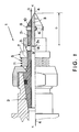
- Fig. 1 shows a lateral view with longitudinal partial cross-section of this embodiment of the pincers according to the invention;
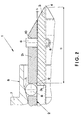
- Fig. 2 shows the same view as in Fig. 1, but expanded and limited to only one part of the end of these pincers.
-
- It should be pointed out that in Figs. 1 and 2, between the area marked 2t of
external casing 2 and thesheath 3 in which the electrode is coaxially situated, there is a certain amount of play (0.1 mm is recommended). - A plurality (the diagram shows four) of threaded
pins 6, screwing into the same number of threadedholes 10--which pass entirely through and which are arranged radially onterminal part 2t ofexternal casing 2--press on the external surface ofsheath 3, and as a function of their penetration, bend this sheath in a predetermined direction and to a predetermined extent, and therefore also bendelectrode 4 contained in this sheath, in such a way as to keep longitudinal axis K-K of thiselectrode 4 perfectly aligned withexternal casing 2, correcting thereby all distortions and errors of various types which as mentioned above generally cause a not insignificant deviation in the relative coaxial positions of the casing andelectrode 4. - Penetration of
pin 6 is obviously adjusted by simultaneous microscopic monitoring of the direction of longitudinal axis K-K ofelectrode 4, thereby obtaining high precision of the microperforations made by electroerosion by cyclic feed and continuous rotation of the electrode. - The inventor has also conceived a much-improved design for
device 5 which locks and unlockselectrode 4 to allow periodic feed. In this embodiment at least one part ofsheath 3 hasnotches 3g (generally three perpendicular to one another) capable of making that part elastically pliable, but pressure on that part and the corresponding pressure on un-notched parts ofsheath 3, instead of the threaded members which current pincers have, is exerted by threespheres 8, wherein the spheres press, by the action of a spring 11, an inclined surface ofrotation 7i (shown as a truncated cone) formed inside ring 7 coaxially external toexternal casing 2. - These three
spheres 8 are accommodated in an equal number ofseats 9 which penetrate completely and which are arranged radially in this sameexternal casing 2. - This design makes it possible to lock
electrode 4 insheath 3 while maintaining optimum centering conditions, ensuring thatelectrode 4 andexternal casing 2 remain virtually coaxial relative to one another and at the locking point ofelectrode 4, and thereby allowing easy automation ofelectrode 4 locking and unlocking operations, using a known system (for example, a fork actuated by a lever or a cam) to cyclically slide ring 7 in an axial direction, overcoming the force exerted by spring 11 to unlockelectrode 4, and ceasing instead to oppose the electrode locking action withinsheath 3. These systems are not shown in the diagrams because they are obvious to one skilled in the art of machine tools. - Any slight defects of alignment between the various axes can therefore be ultimately corrected by making the terminal part of
pincers 1, already described above, with length D of at least 12 mm beginning from the outermost part ofsphere 8 of thisdevice 5 for locking ofelectrode 4. - The inventor of these pincers, in order to be able to reach parts of the workpiece (not shown) inaccessible to current pincers, has also designed the ends of the terminal parts of
external casing 2 and ofsheath 3 to have a tapered shape (substantially conical in the figure here).
Claims (4)
- Automatic pincers (1) for supporting electrodes in an electroerosion device especially suitable for making microperforations, said pincers comprising external casing (2) and inside coaxial sheath (3) made of a metal with high elasticity, in which sheath is coaxially inserted electrode (4), said pincers (1) being equipped with device (5) for reversible locking of this electrode (4) in this sheath (3), a predetermined play (6) existing between terminal section (2t) of said casing (2) and the corresponding terminal section of said sheath (3) coaxially contained therein, and terminal section (2t) of external casing (2) having means (6) for exerting on sheath (3) a pressure perpendicular to the longitudinal axis of external casing (2), in such a way as to bend it to a predetermined degree so as to keep longitudinal axis (K-K) of electrode (4) contained therein aligned with the longitudinal axis of said external casing (2), characterized in that the said device (5) for reversible locking of electrode (4) in sheath (3) is comprised of ring (7) coaxially external to external casing (2), actuated by spring (11) to press with an inclined surface of rotation (71) located inside it, three spheres (8) accommodated in an equal number of seats (9) which penetrate completely and which are arranged radially in external casing (2) and rest against the outer surface of said sheath (3), which has notches (3s) corresponding to at least one of said spheres (8) capable of making at least one of its parts elastically pliable.
- Pincers as claimed in claim 1, wherein said means capable of exerting on sheath (3) a pressure perpendicular to the longitudinal axis of external casing (2) are a plurality of threaded members (6) screwed into holes which penetrate completely (10) and which are arranged radially on terminal part (2t) of said external casing (2).
- Pincers as claimed in any of the preceding claims, wherein said terminal part (2t) of external casing (2) extends by length (D) which is at least 12 mm beginning from the outermost part of spheres (8) of this device (5) for reversibly locking of electrode (4) in sheath (3).
- Pincers as claimed in any of the preceding claims, wherein the ends of the terminal parts of external casing (2) and of sheath (3) have a shape tapered towards the workpiece.
Applications Claiming Priority (3)
| Application Number | Priority Date | Filing Date | Title |
|---|---|---|---|
| CH216496 | 1996-09-03 | ||
| CH216496 | 1996-09-03 | ||
| CH2164/96 | 1996-09-03 |
Publications (2)
| Publication Number | Publication Date |
|---|---|
| EP0826455A1 EP0826455A1 (en) | 1998-03-04 |
| EP0826455B1 true EP0826455B1 (en) | 2000-04-12 |
Family
ID=4227378
Family Applications (1)
| Application Number | Title | Priority Date | Filing Date |
|---|---|---|---|
| EP19970810612 Expired - Lifetime EP0826455B1 (en) | 1996-09-03 | 1997-08-29 | Automatic pincer for electroerosion electrodes |
Country Status (2)
| Country | Link |
|---|---|
| EP (1) | EP0826455B1 (en) |
| DE (1) | DE69701657D1 (en) |
Cited By (1)
| Publication number | Priority date | Publication date | Assignee | Title |
|---|---|---|---|---|
| WO2006092837A1 (en) | 2005-02-28 | 2006-09-08 | Mitsubishi Denki Kabushiki Kaisha | Electrical discharge machine |
Families Citing this family (1)
| Publication number | Priority date | Publication date | Assignee | Title |
|---|---|---|---|---|
| CN100509234C (en) * | 2004-01-23 | 2009-07-08 | 三菱电机株式会社 | Electric discharge machining apparatus |
Family Cites Families (2)
| Publication number | Priority date | Publication date | Assignee | Title |
|---|---|---|---|---|
| DE3475172D1 (en) * | 1983-05-19 | 1988-12-22 | Matsushita Electric Industrial Co Ltd | Electrical discharge machining apparatus for forming minute holes in a workpiece |
| US4782203A (en) * | 1987-04-16 | 1988-11-01 | Raycon Textron Inc. | Wire guide for electric discharge machine |
-
1997
- 1997-08-29 DE DE69701657T patent/DE69701657D1/en not_active Expired - Lifetime
- 1997-08-29 EP EP19970810612 patent/EP0826455B1/en not_active Expired - Lifetime
Cited By (1)
| Publication number | Priority date | Publication date | Assignee | Title |
|---|---|---|---|---|
| WO2006092837A1 (en) | 2005-02-28 | 2006-09-08 | Mitsubishi Denki Kabushiki Kaisha | Electrical discharge machine |
Also Published As
| Publication number | Publication date |
|---|---|
| DE69701657D1 (en) | 2000-05-18 |
| EP0826455A1 (en) | 1998-03-04 |
Similar Documents
| Publication | Publication Date | Title |
|---|---|---|
| CN102015167B (en) | Tool holder with ball clamping mechanism | |
| US5934841A (en) | Round bar cutting tool and cutting tool head for same | |
| US6286823B1 (en) | Workpiece indexing and clamping system | |
| EP0141451A1 (en) | Tool fixing device and tool holder | |
| EP3209240B1 (en) | Milling machine and blank for a dental component | |
| DE1296908B (en) | Chicken cock | |
| EP1986816B1 (en) | Method of coupling a honing tool to a honing spindle, honing spindle, honing tool and honing device | |
| EP1262266B1 (en) | Gripping device | |
| EP0484647B1 (en) | Device for drilling holes with an undercut | |
| EP0568786B1 (en) | Drilling device for making holes with undercuttings | |
| EP0061075A1 (en) | Selfcentering device for attaching tools to the spindle of a machine tool | |
| EP0826455A1 (en) | Automatic pincer for electroerosion electrodes | |
| CA1287484C (en) | Clamping means for machine tool holders | |
| US5388936A (en) | Tool holder | |
| US5137289A (en) | Chuck | |
| EP0556611B1 (en) | Device for adjusting an axially positionable tool locating piece which sits cetrally in a tool-driving spindle. | |
| EP4135929B1 (en) | Device and method for connecting a cooling nozzle to a cooling lubricant supply | |
| EP1740338B1 (en) | Broaching tool and method for machining the surfaces of bores | |
| DE102004042520B3 (en) | Tool carrier for tools on machine tools | |
| DE3817951C2 (en) | ||
| EP0301185A1 (en) | Chucking device for cutting tools like screw-taps, milling cutters or the like, particularly solid hard metal tools | |
| GB2122933A (en) | Setting tool for driving in a threaded rod | |
| US5237146A (en) | Device for fastening an article, disposed at an end of a cylindrical shaft, at a coupling member of a coupling means | |
| US20240082926A1 (en) | Tool holder for a machine tool | |
| SU921696A1 (en) | Chuck for point tool |
Legal Events
| Date | Code | Title | Description |
|---|---|---|---|
| PUAI | Public reference made under article 153(3) epc to a published international application that has entered the european phase |
Free format text: ORIGINAL CODE: 0009012 |
|
| AK | Designated contracting states |
Kind code of ref document: A1 Designated state(s): CH DE FR GB IT LI NL |
|
| 17P | Request for examination filed |
Effective date: 19980430 |
|
| AKX | Designation fees paid | ||
| RBV | Designated contracting states (corrected) | ||
| RBV | Designated contracting states (corrected) |
Designated state(s): AT BE CH DE DK ES LI |
|
| RBV | Designated contracting states (corrected) |
Designated state(s): CH DE FR GB IT LI NL |
|
| 17Q | First examination report despatched |
Effective date: 19990315 |
|
| GRAG | Despatch of communication of intention to grant |
Free format text: ORIGINAL CODE: EPIDOS AGRA |
|
| GRAG | Despatch of communication of intention to grant |
Free format text: ORIGINAL CODE: EPIDOS AGRA |
|
| GRAH | Despatch of communication of intention to grant a patent |
Free format text: ORIGINAL CODE: EPIDOS IGRA |
|
| GRAH | Despatch of communication of intention to grant a patent |
Free format text: ORIGINAL CODE: EPIDOS IGRA |
|
| GRAA | (expected) grant |
Free format text: ORIGINAL CODE: 0009210 |
|
| AK | Designated contracting states |
Kind code of ref document: B1 Designated state(s): CH DE FR GB IT LI NL |
|
| PG25 | Lapsed in a contracting state [announced via postgrant information from national office to epo] |
Ref country code: NL Free format text: LAPSE BECAUSE OF FAILURE TO SUBMIT A TRANSLATION OF THE DESCRIPTION OR TO PAY THE FEE WITHIN THE PRESCRIBED TIME-LIMIT Effective date: 20000412 Ref country code: IT Free format text: LAPSE BECAUSE OF FAILURE TO SUBMIT A TRANSLATION OF THE DESCRIPTION OR TO PAY THE FEE WITHIN THE PRE;WARNING: LAPSES OF ITALIAN PATENTS WITH EFFECTIVE DATE BEFORE 2007 MAY HAVE OCCURRED AT ANY TIME BEFORE 2007. THE CORRECT EFFECTIVE DATE MAY BE DIFFERENT FROM THE ONE RECORDED.SCRIBED TIME-LIMIT Effective date: 20000412 Ref country code: FR Free format text: LAPSE BECAUSE OF FAILURE TO SUBMIT A TRANSLATION OF THE DESCRIPTION OR TO PAY THE FEE WITHIN THE PRESCRIBED TIME-LIMIT Effective date: 20000412 |
|
| REG | Reference to a national code |
Ref country code: CH Ref legal event code: NV Representative=s name: FIAMMENGHI-FIAMMENGHI Ref country code: CH Ref legal event code: EP |
|
| REF | Corresponds to: |
Ref document number: 69701657 Country of ref document: DE Date of ref document: 20000518 |
|
| PG25 | Lapsed in a contracting state [announced via postgrant information from national office to epo] |
Ref country code: DE Free format text: LAPSE BECAUSE OF FAILURE TO SUBMIT A TRANSLATION OF THE DESCRIPTION OR TO PAY THE FEE WITHIN THE PRESCRIBED TIME-LIMIT Effective date: 20000713 |
|
| NLV1 | Nl: lapsed or annulled due to failure to fulfill the requirements of art. 29p and 29m of the patents act | ||
| EN | Fr: translation not filed | ||
| PLBE | No opposition filed within time limit |
Free format text: ORIGINAL CODE: 0009261 |
|
| STAA | Information on the status of an ep patent application or granted ep patent |
Free format text: STATUS: NO OPPOSITION FILED WITHIN TIME LIMIT |
|
| 26N | No opposition filed | ||
| REG | Reference to a national code |
Ref country code: GB Ref legal event code: IF02 |
|
| PGFP | Annual fee paid to national office [announced via postgrant information from national office to epo] |
Ref country code: GB Payment date: 20160805 Year of fee payment: 20 Ref country code: CH Payment date: 20160727 Year of fee payment: 20 |
|
| REG | Reference to a national code |
Ref country code: CH Ref legal event code: PCOW Free format text: NEW ADDRESS: VIA SERRAI 12,, 6592 SANT' ANTONINO (CH) |
|
| REG | Reference to a national code |
Ref country code: CH Ref legal event code: PL |
|
| REG | Reference to a national code |
Ref country code: GB Ref legal event code: PE20 Expiry date: 20170828 |
|
| PG25 | Lapsed in a contracting state [announced via postgrant information from national office to epo] |
Ref country code: GB Free format text: LAPSE BECAUSE OF EXPIRATION OF PROTECTION Effective date: 20170828 |