EP0826427A2 - Oscillating sprinklers - Google Patents
Oscillating sprinklers Download PDFInfo
- Publication number
- EP0826427A2 EP0826427A2 EP97306109A EP97306109A EP0826427A2 EP 0826427 A2 EP0826427 A2 EP 0826427A2 EP 97306109 A EP97306109 A EP 97306109A EP 97306109 A EP97306109 A EP 97306109A EP 0826427 A2 EP0826427 A2 EP 0826427A2
- Authority
- EP
- European Patent Office
- Prior art keywords
- nozzles
- spray bar
- water
- impeller
- bar
- Prior art date
- Legal status (The legal status is an assumption and is not a legal conclusion. Google has not performed a legal analysis and makes no representation as to the accuracy of the status listed.)
- Withdrawn
Links
Images


Classifications
-
- B—PERFORMING OPERATIONS; TRANSPORTING
- B05—SPRAYING OR ATOMISING IN GENERAL; APPLYING FLUENT MATERIALS TO SURFACES, IN GENERAL
- B05B—SPRAYING APPARATUS; ATOMISING APPARATUS; NOZZLES
- B05B3/00—Spraying or sprinkling apparatus with moving outlet elements or moving deflecting elements
- B05B3/02—Spraying or sprinkling apparatus with moving outlet elements or moving deflecting elements with rotating elements
- B05B3/04—Spraying or sprinkling apparatus with moving outlet elements or moving deflecting elements with rotating elements driven by the liquid or other fluent material discharged, e.g. the liquid actuating a motor before passing to the outlet
- B05B3/0409—Spraying or sprinkling apparatus with moving outlet elements or moving deflecting elements with rotating elements driven by the liquid or other fluent material discharged, e.g. the liquid actuating a motor before passing to the outlet with moving, e.g. rotating, outlet elements
- B05B3/0418—Spraying or sprinkling apparatus with moving outlet elements or moving deflecting elements with rotating elements driven by the liquid or other fluent material discharged, e.g. the liquid actuating a motor before passing to the outlet with moving, e.g. rotating, outlet elements comprising a liquid driven rotor, e.g. a turbine
- B05B3/0422—Spraying or sprinkling apparatus with moving outlet elements or moving deflecting elements with rotating elements driven by the liquid or other fluent material discharged, e.g. the liquid actuating a motor before passing to the outlet with moving, e.g. rotating, outlet elements comprising a liquid driven rotor, e.g. a turbine with rotating outlet elements
- B05B3/0431—Spraying or sprinkling apparatus with moving outlet elements or moving deflecting elements with rotating elements driven by the liquid or other fluent material discharged, e.g. the liquid actuating a motor before passing to the outlet with moving, e.g. rotating, outlet elements comprising a liquid driven rotor, e.g. a turbine with rotating outlet elements the rotative movement of the outlet elements being reversible
- B05B3/044—Tubular elements holding several outlets, e.g. apertured tubes, oscillating about an axis substantially parallel to the tubular element
-
- B—PERFORMING OPERATIONS; TRANSPORTING
- B05—SPRAYING OR ATOMISING IN GENERAL; APPLYING FLUENT MATERIALS TO SURFACES, IN GENERAL
- B05B—SPRAYING APPARATUS; ATOMISING APPARATUS; NOZZLES
- B05B1/00—Nozzles, spray heads or other outlets, with or without auxiliary devices such as valves, heating means
- B05B1/14—Nozzles, spray heads or other outlets, with or without auxiliary devices such as valves, heating means with multiple outlet openings; with strainers in or outside the outlet opening
- B05B1/16—Nozzles, spray heads or other outlets, with or without auxiliary devices such as valves, heating means with multiple outlet openings; with strainers in or outside the outlet opening having selectively- effective outlets
- B05B1/1627—Nozzles, spray heads or other outlets, with or without auxiliary devices such as valves, heating means with multiple outlet openings; with strainers in or outside the outlet opening having selectively- effective outlets with a selecting mechanism comprising a gate valve, a sliding valve or a cock
- B05B1/1636—Nozzles, spray heads or other outlets, with or without auxiliary devices such as valves, heating means with multiple outlet openings; with strainers in or outside the outlet opening having selectively- effective outlets with a selecting mechanism comprising a gate valve, a sliding valve or a cock by relative rotative movement of the valve elements
- B05B1/1645—Nozzles, spray heads or other outlets, with or without auxiliary devices such as valves, heating means with multiple outlet openings; with strainers in or outside the outlet opening having selectively- effective outlets with a selecting mechanism comprising a gate valve, a sliding valve or a cock by relative rotative movement of the valve elements the outlets being rotated during selection
- B05B1/1654—Nozzles, spray heads or other outlets, with or without auxiliary devices such as valves, heating means with multiple outlet openings; with strainers in or outside the outlet opening having selectively- effective outlets with a selecting mechanism comprising a gate valve, a sliding valve or a cock by relative rotative movement of the valve elements the outlets being rotated during selection about an axis parallel to the liquid passage in the stationary valve element
-
- B—PERFORMING OPERATIONS; TRANSPORTING
- B05—SPRAYING OR ATOMISING IN GENERAL; APPLYING FLUENT MATERIALS TO SURFACES, IN GENERAL
- B05B—SPRAYING APPARATUS; ATOMISING APPARATUS; NOZZLES
- B05B1/00—Nozzles, spray heads or other outlets, with or without auxiliary devices such as valves, heating means
- B05B1/14—Nozzles, spray heads or other outlets, with or without auxiliary devices such as valves, heating means with multiple outlet openings; with strainers in or outside the outlet opening
- B05B1/20—Arrangements of several outlets along elongated bodies, e.g. perforated pipes or troughs, e.g. spray booms; Outlet elements therefor
- B05B1/202—Arrangements of several outlets along elongated bodies, e.g. perforated pipes or troughs, e.g. spray booms; Outlet elements therefor comprising inserted outlet elements
-
- B—PERFORMING OPERATIONS; TRANSPORTING
- B05—SPRAYING OR ATOMISING IN GENERAL; APPLYING FLUENT MATERIALS TO SURFACES, IN GENERAL
- B05B—SPRAYING APPARATUS; ATOMISING APPARATUS; NOZZLES
- B05B15/00—Details of spraying plant or spraying apparatus not otherwise provided for; Accessories
- B05B15/60—Arrangements for mounting, supporting or holding spraying apparatus
- B05B15/65—Mounting arrangements for fluid connection of the spraying apparatus or its outlets to flow conduits
- B05B15/658—Mounting arrangements for fluid connection of the spraying apparatus or its outlets to flow conduits the spraying apparatus or its outlet axis being perpendicular to the flow conduit
-
- B—PERFORMING OPERATIONS; TRANSPORTING
- B05—SPRAYING OR ATOMISING IN GENERAL; APPLYING FLUENT MATERIALS TO SURFACES, IN GENERAL
- B05B—SPRAYING APPARATUS; ATOMISING APPARATUS; NOZZLES
- B05B3/00—Spraying or sprinkling apparatus with moving outlet elements or moving deflecting elements
- B05B3/02—Spraying or sprinkling apparatus with moving outlet elements or moving deflecting elements with rotating elements
- B05B3/04—Spraying or sprinkling apparatus with moving outlet elements or moving deflecting elements with rotating elements driven by the liquid or other fluent material discharged, e.g. the liquid actuating a motor before passing to the outlet
- B05B3/0409—Spraying or sprinkling apparatus with moving outlet elements or moving deflecting elements with rotating elements driven by the liquid or other fluent material discharged, e.g. the liquid actuating a motor before passing to the outlet with moving, e.g. rotating, outlet elements
- B05B3/0418—Spraying or sprinkling apparatus with moving outlet elements or moving deflecting elements with rotating elements driven by the liquid or other fluent material discharged, e.g. the liquid actuating a motor before passing to the outlet with moving, e.g. rotating, outlet elements comprising a liquid driven rotor, e.g. a turbine
- B05B3/0422—Spraying or sprinkling apparatus with moving outlet elements or moving deflecting elements with rotating elements driven by the liquid or other fluent material discharged, e.g. the liquid actuating a motor before passing to the outlet with moving, e.g. rotating, outlet elements comprising a liquid driven rotor, e.g. a turbine with rotating outlet elements
- B05B3/0431—Spraying or sprinkling apparatus with moving outlet elements or moving deflecting elements with rotating elements driven by the liquid or other fluent material discharged, e.g. the liquid actuating a motor before passing to the outlet with moving, e.g. rotating, outlet elements comprising a liquid driven rotor, e.g. a turbine with rotating outlet elements the rotative movement of the outlet elements being reversible
- B05B3/0436—Spraying or sprinkling apparatus with moving outlet elements or moving deflecting elements with rotating elements driven by the liquid or other fluent material discharged, e.g. the liquid actuating a motor before passing to the outlet with moving, e.g. rotating, outlet elements comprising a liquid driven rotor, e.g. a turbine with rotating outlet elements the rotative movement of the outlet elements being reversible by reversing the direction of rotation of the rotor itself
Definitions
- This invention relates to oscillating sprinklers for watering gardens.
- an oscillating sprinkler comprises support means, a spray bar which is capable of oscillating movement with respect to the support means, the spray bar having outlet nozzles for delivering water, an impeller which is driven by the flow of incoming water to the sprinkler, the impeller driving the spray bar with said oscillating movement, the spray bar having a first set of outlet nozzles and a second set of outlet nozzles and the bar being movable between two operative positions in the first of which water is in use delivered to the first set but not the second set and in the second position of which water is in use delivered to the second set but not the first set.
- the first set of nozzles will normally differ from the second set of nozzles in terms of the respective water spray patterns produced, to give the user a choice of water spray patterns.
- the spray bar is preferably generally cylindrical, having the first set of nozzles extending in a line, substantially parallel to the longitudinal axis of the bar, and having the second set of nozzles extending substantially parallel to the longitudinal axis of the bar, with the line of the first set of nozzles being diametrically opposite the line of the second set of nozzles.
- the bar is preferably rotatable, with respect to the remainder of the sprinkler, about an axis coincident with the central longitudinal axis of the bar, and detent means may be provided positively to locate the bar in each of the first and second positions.
- the bar has a first water flow passage leading to the first set of nozzles and a second water flow passage leading to the second set of nozzles, water from the impeller being delivered to the first passage but not the second passage when the bar is in the first position and water from the impeller being delivered to the second passage but not the first passage when the bar is in the second position.
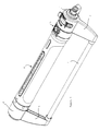
- the sprinkler comprises a support structure including two end supports 1, 2.
- Each support 1 or 2 has a pair of splayed legs 3 with lower ground-engaging ends interconnected by a pair of longitudinally extending bars 4.
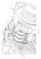
- Between the end supports 1, 2 are disposed an impeller assembly 5 and a spray bar assembly 6 which is generally cylindrical.
- the end support 1 includes a spigot 7 (omitted from Figure 1) for connection of a hose fitting, enabling water to be supplied to the end support 1.
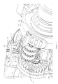
- the impeller assembly 5 includes an impeller 8 and a reduction gear train 9. The incoming water flow drives the impeller 8 which, through the reduction gear train 9, applies an oscillating motion to the spray bar assembly 6 which has nozzles from which the water is delivered.
- the toggle valve 16 has a rocker member 17 from which projects a lever surrounded by a helical spring 18. The lever is extended to form a switching arm 19 which extends into the end support 1.
- the rocker member 17 is moved to the position illustrated in Figure 8 in which the inlet 15 is open to enable water to enter the inlet 15 whilst the inlet 14 is blocked by the member 17.
- the rocker member 17 moves over centre to the alternative (non-illustrated) position, in which the inlet 14 is open for the passage of water and the inlet 15 is closed.
- the gear train 9 runs in the chamber 13.
- Movement of the arm 19 is effected by two sweep setting rings 20, 22 (Fig. 7) mounted for independent rotational adjusting movement about the central longitudinal axis of the sprinkler and with respect to the end support 1.
- Each ring 20, 22 has a radial wall provided with an aperture through which the arm 19 extends, and the edge of each aperture is capable of being engaged by the arm 19 to cause change-over of the rocker member 17.
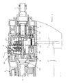
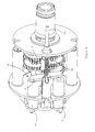
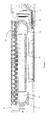
- the impeller assembly 5 has a water flow path which by-passes the impeller 8. This by-pass path is indicated by the arrow 25 in Figure 4. As can be seen, the by-pass path leaves the impeller inlet chamber 13 by means of a passage 26 the inlet port to which is closable by a rotatably movable valve member 27. The passage 26 leads water, without interruption, into the impeller outlet chamber 23.
- the valve member 27 is moulded with a stem which is rotatably mounted in the outer housing 28 of the impeller assembly 5. Below the stem projects a peg 29 ( Figure 3) which, in the closed condition of the by-pass valve ( Figure 5), covers and effectively obstructs the inlet port to the passage 26 to prevent water passing through the by-pass passage 25. Rotation of the valve member 27 through about 90° from its closed position, causes the peg 29 to move away from the inlet port so as to open the valve and allow water to pass through the by-pass passage 25, this position being illustrated in Figures 4 and 6.
- valve member 27 has an externally accessible disc-like top 30 provided with a diametral slot for entry of a coin edge, to facilitate rotational movement of the valve member 27.
- the housing adjacent the member 27 may bear water pressure markings, to guide the user in positioning the valve member to suit the prevailing inlet water pressure.
- the by-pass passage 25 acts to compensate for variations in water supply pressure between different users, and possibly for variations experienced by a particular user.
- the user opens the by-pass valve to enable a proportion of the water to reach the spray bar without passing through the impeller 8. This increases the volumetric flow rate of water reaching the spray bar, compared with the condition where all the water passes through the impeller.
- the by-pass valve is closed so that all the water passes through and drives the impeller 8.
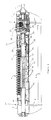
- the whole spray bar assembly 6 is rotatable, about the central longitudinal axis of the sprinkler, between two alternative operative positions respectively shown in Figures 9 and 10.
- a detent retains the spray bar assembly in the selected one of the two positions which are angularly displaced by 180°.
- a first set 32 of twenty nozzles is in the operative upwardly facing position.
- a second set 33 of five nozzles is in the operative upwardly facing position.
- Each of the sets of nozzles is in a line parallel to the longitudinal axis of the sprinkler bar.
- the housing 34 of the spray bar assembly is rotatable with respect to the impeller housing, the rotational interface being indicated at 35 in Figures 9 and 10.
- the housing of the spray bar assembly adjoins an adjusting ring 36, the purpose of which will be described.
- the ring 36 rotates with the spray bar assembly 6, when the latter is rotated between the Figure 9 and 10 positions, and reference 37 indicates the rotational interface between the spray bar assembly 6 and the end support 2.
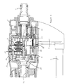
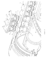
- a cup-like chamber 38 into which the duct 24 projects.
- the circumferential wall of the cup-like chamber has two oppositely positioned side ports 39, 40 which are selectively opened and closed by the angled end of the duct 24.
- An angled seal 41 surrounds the end of the duct 24 and seals against the wall of the cup-like chamber.
- the side port 39 is blanked off by the wall of the duct 24, but the other side port 40 is open and allows water to enter a first flow path 42 which extends through the centre of the spray bar and communicates with the first set 32 of nozzles.
- the port 40 When the spray bar assembly is grasped and rotated through 180° to the alternative position shown in Figure 10, the port 40 is blanked off by the end of the duct 24, but the port 39 is open and allows water to enter a second flow path 43 through the upper region of the spray bar assembly, so as to lead water to the second set 33 of nozzles.
- the characteristics of the two sets of nozzles 32 and 33 differ and the sets of nozzles 32, 33 are on opposite sides of the spray bar.
- the nozzles 33 produce a finer jet spray than the nozzles 32.
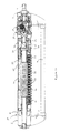
- a central stem 44 which rotates with the remainder of the spray bar assembly when the latter is moved between the Figure 9 and Figure 10 positions, but which is capable of rotational movement with respect to the remaining outer structure of the spray bar assembly under the control of the adjusting ring 36.
- the stem has spaced cylindrical portions 45 interconnected by longitudinally extending bars or strips 46, and each cylindrical portion 45 has, extending therearound and at a skew angle, a corresponding O-ring seal 47 the outer periphery of which seals against the surrounding structure of the spray bar assembly.
- the O-ring seals 47 are best seen in Figures 11 to 14.
- Figure 11 illustrates the condition where the maximum number of nozzles (six) are isolated, leaving the central fourteen nozzles operative. The other extreme is shown in Figure 14 where all twenty nozzles 32 are operative.
- Figures 12 and 13 show intermediate positions where sixteen and eighteen nozzles, respectively, are operative.
- the first set of twenty nozzles 32 are formed in four separately moulded plastics strips, namely a first (and end) strip bearing three nozzles, a second strip bearing seven nozzles, a third strip bearing seven nozzles and a fourth (and end) strip bearing three nozzles.
- the first and second strips are illustrated at 48 and 49 respectively in Figure 16.
- the strip 48 is shown ready for insertion in the spray bar housing and the strip 49 is shown snapped into position in the spray bar housing.
- the end strip 48 is integrally moulded, having a plate-like flange 50 from the upper surface of which project three bulbous projections 52 each with an orifice angled in a particular direction. Below the flange 50, are three stems each of which has a pair of resilient tabs 53 and an elastomeric O-ring seal 54.
- the strip 48 fits into the end of the spray bar housing which is moulded with three sockets 55 for the respective reception of the three stems.
- the strip 48 is pressed into position, with the resilient tabs 53 snapping into position in opposed slots 56 formed in the walls of the sockets and with the O-rings 54 sealing against the bases of the socket walls.
- the other strips are similarly formed and pressed into position with a snap fit which retains the strips in position.
- the nozzle characteristics can be varied without the need to alter the mould tools for making the remainder of the sprinkler. Also, the angling of the orifices in the nozzles make it virtually impossible to form all the nozzles in one moulding, so the use of individual strips gives greater flexibility in angling the nozzles.
Landscapes
- Nozzles (AREA)
- Catching Or Destruction (AREA)
Abstract
Description
Claims (17)
- An oscillating sprinkler comprising support means, a spray bar which is capable of oscillating movement with respect to the support means, the spray bar having outlet nozzles for delivering water, an impeller which is driven by the flow of incoming water to the sprinkler, the impeller driving the spray bar with said oscillating movement, the spray bar having a first set of outlet nozzles and a second set of outlet nozzles and the bar being movable between two operative positions in the first of which water is in use delivered to the first set but not the second set and in the second position of which water is in use delivered to the second set but not the first set.
- An oscillating sprinkler according to claim 1, wherein the spray bar is generally cylindrical, having the first set of nozzles extending in a line substantially parallel to the longitudinal axis of the bar, and having the second set of nozzles extending in a line substantially parallel to the longitudinal axis of the bar, with the line of the first set of nozzles being diametrically opposite the line of the second set of nozzles.
- An oscillating sprinkler according to claim 1 or 2, wherein the bar is rotatable, with respect to the remainder of the sprinkler, about an axis coincident with the central longitudinal axis of the bar, and detent means are provided positively to locate the bar in each of the first and second positions.
- An oscillating sprinkler according to any of the preceding claims, wherein the bar has a first water flow passage leading to the first set of nozzles and a second water tlow passage leading to the second set of nozzles, water from the impeller being delivered to the first passage but not the second passage when the bar is in the first position and water from the impeller being delivered to the second passage but not the first passage when the bar is in the second position.
- An oscillating sprinkler according to any of the preceding claims, wherein the sprinkler has a by-pass passage which allows water to reach the spray bar without passing through the impeller and a valve for controlling the flow of water through the by-pass passage.
- An oscillating sprinkler according to claim 5, wherein the sprinkler comprises a spray bar assembly, including the spray bar, and an impeller assembly, including the impeller, the spray bar assembly and the impeller assembly being driven together with said oscillating movement with respect to the support means which are provided with ground-engaging feet.
- An oscillating sprinkler according to claim 6, wherein the flow valve includes a flow valve member rotatably mounted in a housing of the impeller assembly, the flow valve member having an externally accessible portion for manual adjustment of the flow valve.
- An oscillating sprinkler according to claim 7, wherein the flow valve member has a projecting peg which progressively opens or obstructs a port forming part of said by-pass passage, so that rotational adjustment of the flow valve member provides progressive opening and closing of the port so to enable the volume of water passing through the by-pass passage to be varied.
- An oscillating sprinkler according to any of the preceding claims, wherein adjustable selection means are provided selectively to isolate the water supply to certain of the nozzles in one of the sets in order to vary the number of operative nozzles which deliver water.
- An oscillating sprinkler according to claim 9, wherein the selection means include a central stem rotatable with respect to the spray bar to vary the number of operative nozzles in said one set.
- An oscillating sprinkler according to claim 10, wherein the central stem carries two spaced O-rings which surround the central stem at skewed angles so that rotation of the central stem progressively isolates the number of nozzles in said one set in communication with the water supply.
- An oscillating sprinkler according to claim 10 or 11, wherein the selection means includes a manually adjustable ring rotation of which causes rotation of the central stem with respect to the spray bar.
- An oscillating sprinkler according to claim 12, wherein the adjusting ring is disposed at the end of the spray bar remote from the impeller.
- An oscillating sprinkler according to any of claims 9 to 13, wherein the selection means are adjustable between maximum and minimum limit positions respectively defined by all the nozzles in a line thereof being operative and the minimum number of nozzles being operative, adjustment of the selection means from the maximum position causing progressive isolation of the nozzles from each end of the line of the nozzles so that in the minimum position the operative nozzles are constituted by a central group in the line of nozzles.
- An oscillating sprinkler according to any of claims 9 to 14, wherein the spray bar comprises a spray bar housing and at least one separately formed strip carrying the nozzles of the first set or the second set, on assembly of the sprinkler the strip being snap fitted to the housing.
- An oscillating sprinkler according to claim 15, wherein the spray bar housing is formed with a line of sockets and the or each strip presents upwardly facing nozzles and downwardly projecting nozzle stems which are snap fitted into the sockets to retain the strip with respect of the spray bar housing.
- An oscillating sprinkler according to claim 16, wherein there are four such strips which are snap fitted into the spray bar housing in a single line to form the line of nozzles in the spray bar.
Applications Claiming Priority (6)
| Application Number | Priority Date | Filing Date | Title |
|---|---|---|---|
| GBGB9618102.9A GB9618102D0 (en) | 1996-08-30 | 1996-08-30 | Oscillating sprinklers |
| GBGB9618173.0A GB9618173D0 (en) | 1996-08-30 | 1996-08-30 | Oscillating sprinklers |
| GB9618173 | 1996-08-30 | ||
| GB9618172 | 1996-08-30 | ||
| GBGB9618172.2A GB9618172D0 (en) | 1996-08-30 | 1996-08-30 | Oscillating sprinklers |
| GB9618102 | 1996-08-30 |
Publications (2)
| Publication Number | Publication Date |
|---|---|
| EP0826427A2 true EP0826427A2 (en) | 1998-03-04 |
| EP0826427A3 EP0826427A3 (en) | 1999-01-07 |
Family
ID=27268454
Family Applications (1)
| Application Number | Title | Priority Date | Filing Date |
|---|---|---|---|
| EP97306109A Withdrawn EP0826427A3 (en) | 1996-08-30 | 1997-08-11 | Oscillating sprinklers |
Country Status (1)
| Country | Link |
|---|---|
| EP (1) | EP0826427A3 (en) |
Cited By (20)
| Publication number | Priority date | Publication date | Assignee | Title |
|---|---|---|---|---|
| WO2005020663A1 (en) | 2003-08-29 | 2005-03-10 | Elgo Irrigation Ltd. | Oscillating sprinkler with a self contained fertilizing unit and method of applying fertilizer with the same |
| US7090146B1 (en) | 2004-03-23 | 2006-08-15 | Orbit Irrigation Products, Inc. | Above-ground adjustable spray pattern sprinkler |
| US7252246B2 (en) | 2004-11-12 | 2007-08-07 | L.R. Nelson Corporation | Oscillating sprinkler with pattern select feature |
| AU2006200485B2 (en) * | 2005-11-30 | 2008-02-21 | Yuan Mei Corp. | Automatic water inlet switching device for an oscillating sprinkler |
| US7419105B2 (en) | 2005-11-30 | 2008-09-02 | Yuan Mei Corp. | Spray oscillating control apparatus for sprinklers |
| US7624934B2 (en) | 2005-02-02 | 2009-12-01 | Robert Bosch Tool Corporation | Wind resistant oscillating sprinkler |
| CN101015822B (en) * | 2006-02-10 | 2010-06-23 | 源美股份有限公司 | Water-entry automatic change-over device for water sprinkler |
| DE202013005525U1 (en) | 2013-06-20 | 2013-10-04 | Chia-Tsung Chang | Changeover valve for a sprinkler |
| US20140070023A1 (en) * | 2012-09-12 | 2014-03-13 | Pai-Chou Hsieh | Oscillating Sprinkler with Toggle Valve |
| WO2014150775A1 (en) * | 2013-03-15 | 2014-09-25 | Robert Bosch Gmbh | Water sprinkler |
| US8910887B2 (en) | 2010-07-15 | 2014-12-16 | Partners In Innovation, Ltd. | Garden watering device |
| US9597699B2 (en) | 2011-03-04 | 2017-03-21 | Partners In Innovation Limited, Llc | Water flow metering device |
| US9724708B2 (en) | 2009-12-17 | 2017-08-08 | Partners In Innovation Ltd. | Garden watering device |
| USD825716S1 (en) | 2017-05-03 | 2018-08-14 | Partners In Innovation Limited, Llc | Sprinkler with fold-out legs |
| USD827090S1 (en) | 2017-05-03 | 2018-08-28 | John A. Helmsderfer | Lawn and garden sprinkler |
| WO2022026861A1 (en) * | 2020-07-30 | 2022-02-03 | Melnor, Inc. | Sprinkler nozzle spray width indicator apparatus and method |
| DE202022104309U1 (en) | 2022-07-28 | 2022-08-09 | Yuan Pin Industrial Co., Ltd. | Water flow switching device for sprinklers |
| US11497374B2 (en) | 2020-02-19 | 2022-11-15 | Midea Group Co., Ltd. | Dishwasher with wall-mounted rotatable conduit |
| US11564551B2 (en) | 2020-09-16 | 2023-01-31 | Midea Group Co., Ltd | Dishwasher with molded tubular spray element |
| US11826001B2 (en) | 2022-02-15 | 2023-11-28 | Midea Group Co., Ltd. | Dishwasher with tubular spray element including elongated metal tube and retaining tab for mounting support member thereto |
Family Cites Families (2)
| Publication number | Priority date | Publication date | Assignee | Title |
|---|---|---|---|---|
| US3332624A (en) * | 1965-01-28 | 1967-07-25 | First Res Corp | Turret lawn sprinkler with oscillating mechanism |
| US5305956A (en) * | 1992-08-03 | 1994-04-26 | Wang H | Oscillatory sprinkler |
-
1997
- 1997-08-11 EP EP97306109A patent/EP0826427A3/en not_active Withdrawn
Non-Patent Citations (1)
| Title |
|---|
| None |
Cited By (27)
| Publication number | Priority date | Publication date | Assignee | Title |
|---|---|---|---|---|
| WO2005020663A1 (en) | 2003-08-29 | 2005-03-10 | Elgo Irrigation Ltd. | Oscillating sprinkler with a self contained fertilizing unit and method of applying fertilizer with the same |
| US7090146B1 (en) | 2004-03-23 | 2006-08-15 | Orbit Irrigation Products, Inc. | Above-ground adjustable spray pattern sprinkler |
| US7252246B2 (en) | 2004-11-12 | 2007-08-07 | L.R. Nelson Corporation | Oscillating sprinkler with pattern select feature |
| US7624934B2 (en) | 2005-02-02 | 2009-12-01 | Robert Bosch Tool Corporation | Wind resistant oscillating sprinkler |
| AU2006200485B8 (en) * | 2005-11-30 | 2008-07-03 | Yuan Mei Corp. | Automatic water inlet switching device for an oscillating sprinkler |
| US7419105B2 (en) | 2005-11-30 | 2008-09-02 | Yuan Mei Corp. | Spray oscillating control apparatus for sprinklers |
| US7422162B2 (en) | 2005-11-30 | 2008-09-09 | Yuan Mei Corp. | Automatic water inlet switching device for an oscillating sprinkler |
| DE102006021053B4 (en) * | 2005-11-30 | 2013-11-14 | Yuan Mei Corp. | Automatic water inlet switching device for a swiveling sprinkler |
| AU2006200485B2 (en) * | 2005-11-30 | 2008-02-21 | Yuan Mei Corp. | Automatic water inlet switching device for an oscillating sprinkler |
| CN101015822B (en) * | 2006-02-10 | 2010-06-23 | 源美股份有限公司 | Water-entry automatic change-over device for water sprinkler |
| US9724708B2 (en) | 2009-12-17 | 2017-08-08 | Partners In Innovation Ltd. | Garden watering device |
| US10525487B2 (en) | 2009-12-17 | 2020-01-07 | Partners In Innovation Limited, Llc | Garden watering device |
| US8910887B2 (en) | 2010-07-15 | 2014-12-16 | Partners In Innovation, Ltd. | Garden watering device |
| US9597699B2 (en) | 2011-03-04 | 2017-03-21 | Partners In Innovation Limited, Llc | Water flow metering device |
| US20140070023A1 (en) * | 2012-09-12 | 2014-03-13 | Pai-Chou Hsieh | Oscillating Sprinkler with Toggle Valve |
| US9016597B2 (en) * | 2012-09-12 | 2015-04-28 | Yuan Pin Industrial Co., Ltd. | Oscillating sprinkler with toggle valve |
| WO2014150775A1 (en) * | 2013-03-15 | 2014-09-25 | Robert Bosch Gmbh | Water sprinkler |
| US9669420B2 (en) | 2013-03-15 | 2017-06-06 | Fiskars Oyj Abp | Water sprinkler |
| DE202013005525U1 (en) | 2013-06-20 | 2013-10-04 | Chia-Tsung Chang | Changeover valve for a sprinkler |
| USD825716S1 (en) | 2017-05-03 | 2018-08-14 | Partners In Innovation Limited, Llc | Sprinkler with fold-out legs |
| USD827090S1 (en) | 2017-05-03 | 2018-08-28 | John A. Helmsderfer | Lawn and garden sprinkler |
| US11497374B2 (en) | 2020-02-19 | 2022-11-15 | Midea Group Co., Ltd. | Dishwasher with wall-mounted rotatable conduit |
| WO2022026861A1 (en) * | 2020-07-30 | 2022-02-03 | Melnor, Inc. | Sprinkler nozzle spray width indicator apparatus and method |
| US11992853B2 (en) | 2020-07-30 | 2024-05-28 | Melnor, Inc. | Sprinkler nozzle spray width indicator apparatus and method |
| US11564551B2 (en) | 2020-09-16 | 2023-01-31 | Midea Group Co., Ltd | Dishwasher with molded tubular spray element |
| US11826001B2 (en) | 2022-02-15 | 2023-11-28 | Midea Group Co., Ltd. | Dishwasher with tubular spray element including elongated metal tube and retaining tab for mounting support member thereto |
| DE202022104309U1 (en) | 2022-07-28 | 2022-08-09 | Yuan Pin Industrial Co., Ltd. | Water flow switching device for sprinklers |
Also Published As
| Publication number | Publication date |
|---|---|
| EP0826427A3 (en) | 1999-01-07 |
Similar Documents
| Publication | Publication Date | Title |
|---|---|---|
| EP0826427A2 (en) | Oscillating sprinklers | |
| US6802458B2 (en) | Sprinkler with nozzle gate valve | |
| US6454186B2 (en) | Multi-functional shower head | |
| US7090146B1 (en) | Above-ground adjustable spray pattern sprinkler | |
| CA2190866C (en) | Unitized sprinkler assembly with adjustable water control mechanism | |
| US7322533B2 (en) | Rotary stream sprinkler with adjustable deflector ring | |
| US7581687B2 (en) | Spray nozzle with selectable deflector surface | |
| US8684283B2 (en) | Variable range sprinkler apparatus and variable range sprinkler pattern method | |
| EP0713426B1 (en) | Lawn sprinkler with cam controlled variable spray pattern | |
| CA1150204A (en) | Device for controlling the flow of fluid | |
| US5098020A (en) | Adjustable oscillating wave-type sprinkler | |
| US20050194464A1 (en) | Adjustable sprinkler | |
| EP0724913A2 (en) | Adjustable arc spray nozzle | |
| US7252246B2 (en) | Oscillating sprinkler with pattern select feature | |
| EP1563910A1 (en) | Liquid spraying pistol with variable jet for gardening | |
| CA3118300C (en) | Sprayer | |
| KR20050081837A (en) | Hose-end sprayer assembly | |
| US9662668B1 (en) | Matched precipitation rate rotor-type sprinkler with selectable nozzle ports | |
| US9120111B2 (en) | Arc adjustable rotary sprinkler having full-circle operation and automatic matched precipitation | |
| US9016597B2 (en) | Oscillating sprinkler with toggle valve | |
| US5042719A (en) | Oscillating lawn sprinkler | |
| US6170765B1 (en) | Pressure actuated shower head mechanism | |
| US6354518B1 (en) | Pressure actuated shower head mechanism | |
| AU8611598A (en) | Pressure actuated shower head mechanism | |
| CN116713136A (en) | Swing type sprinkler |
Legal Events
| Date | Code | Title | Description |
|---|---|---|---|
| PUAI | Public reference made under article 153(3) epc to a published international application that has entered the european phase |
Free format text: ORIGINAL CODE: 0009012 |
|
| AK | Designated contracting states |
Kind code of ref document: A2 Designated state(s): DE FR GB IT |
|
| AX | Request for extension of the european patent |
Free format text: AL;LT;LV;RO;SI |
|
| PUAL | Search report despatched |
Free format text: ORIGINAL CODE: 0009013 |
|
| AK | Designated contracting states |
Kind code of ref document: A3 Designated state(s): AT BE CH DE DK ES FI FR GB GR IE IT LI LU MC NL PT SE |
|
| AX | Request for extension of the european patent |
Free format text: AL;LT;LV;RO;SI |
|
| AKX | Designation fees paid |
Free format text: DE FR GB IT |
|
| STAA | Information on the status of an ep patent application or granted ep patent |
Free format text: STATUS: THE APPLICATION IS DEEMED TO BE WITHDRAWN |
|
| 18D | Application deemed to be withdrawn |
Effective date: 19990708 |