EP0826421A2 - Improvements in or relating to crushing machines - Google Patents

Improvements in or relating to crushing machines Download PDF

Info

Publication number
EP0826421A2
EP0826421A2 EP97306543A EP97306543A EP0826421A2 EP 0826421 A2 EP0826421 A2 EP 0826421A2 EP 97306543 A EP97306543 A EP 97306543A EP 97306543 A EP97306543 A EP 97306543A EP 0826421 A2 EP0826421 A2 EP 0826421A2
Authority
EP
European Patent Office
Prior art keywords
tension
crusher
bush
piston
assembly
Prior art date
Legal status (The legal status is an assumption and is not a legal conclusion. Google has not performed a legal analysis and makes no representation as to the accuracy of the status listed.)
Withdrawn
Application number
EP97306543A
Other languages
German (de)
French (fr)
Other versions
EP0826421A3 (en
Inventor
Gerald Cavan Pratt
Christopher David Hall
Graham Thomas Henry Phipps
Current Assignee (The listed assignees may be inaccurate. Google has not performed a legal analysis and makes no representation or warranty as to the accuracy of the list.)
Individual
Original Assignee
Individual
Priority date (The priority date is an assumption and is not a legal conclusion. Google has not performed a legal analysis and makes no representation as to the accuracy of the date listed.)
Filing date
Publication date
Application filed by Individual filed Critical Individual
Publication of EP0826421A2 publication Critical patent/EP0826421A2/en
Publication of EP0826421A3 publication Critical patent/EP0826421A3/en
Withdrawn legal-status Critical Current

Links

Images

Classifications

    • BPERFORMING OPERATIONS; TRANSPORTING
    • B02CRUSHING, PULVERISING, OR DISINTEGRATING; PREPARATORY TREATMENT OF GRAIN FOR MILLING
    • B02CCRUSHING, PULVERISING, OR DISINTEGRATING IN GENERAL; MILLING GRAIN
    • B02C1/00Crushing or disintegrating by reciprocating members
    • B02C1/02Jaw crushers or pulverisers
    • B02C1/025Jaw clearance or overload control

Definitions

  • This invention relates to improvements in or relating to crushing machines, and in particular to improvements relating to the automatic tensioning of jaw crusher tension rod systems and a mechanism useful for that purpose.
  • jaw crushers In jaw crushers a jawstock with a swing jaw oscillates to and fro with respect to a fixed jaw. This motion crushes rock passing between the jaws, and the size of the crushed rock is determined by the distance between faces of the jaws. This gap is called the crusher setting.
  • the jawstock is mounted on an eccentric drive shaft and this, combined with a freely supported toggle plate, creates the crushing action.
  • the setting of the crusher is varied by means of an adjustable toggle block mounted within a toggle beam.
  • the toggle plate is prevented from falling from between the jawstock toggle seat and the toggle block by a tension rod and compression spring.
  • One end of the rod is connected to the jawstock and the other to the toggle beam via springs.
  • a jaw crusher comprises an oscillating jaw having an operating setting which is adjustable by means of a toggle device connected to the oscillating jaw by a freely supported toggle plate, the oscillating jaw and the toggle device being connected and held in tension by a tension rod assembly, wherein there are provided means for determining the tension applied to the tension rod assembly, comparing the measured tension with a pre-set value and adjusting the tension to the pre-set value.
  • the jaw crusher according to the invention is advantageous primarily in that the tension rod assembly is adjusted automatically whenever the operating setting of the crusher is altered. This eliminates the need for manual adjustment, reducing machine down-time and ensuring consistency of operation.
  • the tension rod assembly is preferably pivotally connected to the oscillating jaw and is preferably connected at its other end to a bracket fixed to the toggle device.
  • the tension rod assembly is preferably tensioned by a compression spring mounted about the assembly and acting between the bracket and a flange or the like at the end of the assembly.
  • the means for adjusting the tension in the tension rod assembly preferably comprises means for adjusting the effective length of the assembly.
  • Such means most preferably comprises a fluid driven piston and cylinder, most preferably a hydraulic arrangement.
  • the piston in such an arrangement is, or forms part of, the tension rod assembly, movement of the piston within the cylinder effectively altering the length of the assembly.
  • a locking device for this purpose comprises a split bush which surrounds the piston rod and a second bush having a cam surface which bears against the split bush to urge the split bush into engagement with the piston rod.
  • Such a locking device may be useful in any situation in which a rod or shaft is to be locked against movement, and according to another aspect of the invention there is provided a locking device for a movable shaft or rod, the locking device comprising a split bush which surrounds the shaft or rod and a second bush movable from a locking position, in which a cam surface of the second bush bears against the split bush so as to urge the split bush into locking engagement with the shaft or rod, to an unlocked position in which the split bush is released from the rod or shaft.
  • Comparison of the measured tension in the tension rod assembly with the pre-set value, and adjustment of the tension in response to that comparison is preferably performed automatically, under computer control.
  • a jaw crusher comprises a fixed jaw 1 and an oscillating jaw 2 fixed to a jawstock 3.
  • the size of the crushed product is determined by the closest separation of the fixed jaw 1 and the oscillating jaw 2. This distance is known as the crusher setting and is indicated by the arrows D.
  • the jawstock 3 is connected to a toggle block 4 by a toggle plate 5, one end of which locates in a jawstock toggle seat 6.
  • the toggle block 4 is mounted on a toggle beam 7.
  • the jawstock 3 has a jawstock pivot bracket 8 to which is connected one end of a tension rod assembly.
  • This assembly comprises a piston rod 9 connected to a piston 17 (see Figure 3) housed within a single acting hydraulic cylinder 10, the end of which is connected to a fixed rod 11.
  • the fixed rod 11 passes through a toggle beam pivot bracket 12 which carries a spring cup 13.
  • the end of the fixed rod 11 carries a spring disc 14, a compression spring 15 being mounted about the terminal portion of the fixed rod 11, between the disc 14 and the spring cup 13.
  • the effect of the compression spring 15 is to apply tension to the tension rod assembly, and hence to apply tension to hold the toggle plate 5 in place between the toggle block 4 and the jawstock 3.
  • the disc 14 is bushed for sliding movement on the fixed rod 11, the terminal portion of the fixed rod 11 being threaded and carrying nuts 16 by which the position of the disc 14, and hence the compression applied to the spring 15, can be adjusted.
  • the toggle block 4 is moved backwards or forwards respectively. Movement of the toggle block 4 is accomplished by means of hydraulic cylinders (not shown in Figure 1) which are mounted on top of the toggle beam 7 within the frame of the crusher.
  • Movement of the jawstock 3 to adjust the setting D alters the tension in the spring 15.
  • the tension rod assembly of piston rod 9 and cylinder 10 is intended to provide automatic correction of this.
  • FIG 2 shows the hydraulic circuitry controlling the adjustment of the setting D and also the automatic correction of the tension in the tension rod assembly.
  • adjustment of the setting D is carried out by operation of hydraulic cylinders mounted on the toggle beam 7.
  • These cylinders are indicated in Figure 2 by the numerals 21,22 and are attached in a known manner to taper wedges (not shown) which are arranged to slide over each other. Extending the cylinders 21,22 will reduce the setting D, retracting them will increase the setting D.
  • valves to operate the cylinders 10,21,22 are mounted on a 3 station manifold block, and include the following:
  • the locking device 16 comprises a cylindrical casing 35 formed integrally with the end of the cylinder 10.
  • a split bush 31 is mounted on the piston rod 9 and is formed on its external surface with a series of wedge-shaped camming surfaces which mate with correspondingly formed surfaces on a second bush 32. The arrangement is such that slight axial movement of the second bush 32 relative to the split bush 31 causes the cam surfaces of the second bush 32 to bear against the corresponding surfaces of the split bush 31 and thereby to urge the split bush 31 into frictional engagement with the piston rod 9.
  • Spring disc washers 33 are mounted about the piston rod 9 and act on the second bush 32 so as to bias it into engagement with the split bush 31, and hence into the locked condition.
  • hydraulic fluid is pumped into an annular chamber 34 where it acts on an unlocking piston 36 which in turn bears against the second bush 32.
  • the action of the unlocking piston 36 causes the second bush 32 to disengage from the split bush 31, and hence releases the split bush 31 from the piston rod 9, allowing the latter to move.
  • the piston rod 9 has moved to its desired position the fluid pressure in the chamber 34 is released, whereupon the second bush 32 engages the split bush 31, under the action of the disc washers 33, and locks the piston rod 9.
  • Correction of the tension in the tension rod assembly is carried out, with the locking device 16 unlocked as described above, by applying hydraulic pressure to one side or other of the cylinder 10.
  • the hydraulic pressure in the cylinder 10 is adjusted by means of the pressure reducing valve V4 and/or the counterbalance valve V5 until it reaches a pre-set value. Once that pre-set value has been reached, the hydraulic pressure to the locking device 16 is released, causing the position of the piston rod 9 and hence the overall length of the tension rod assembly to become fixed.

Landscapes

  • Engineering & Computer Science (AREA)
  • Mechanical Engineering (AREA)
  • Food Science & Technology (AREA)
  • Crushing And Grinding (AREA)

Abstract

A jaw crusher comprises an oscillating jaw (2,3) having an operating setting D which is adjustable by means of a toggle device (7) connected to the oscillating jaw (2,3) by a freely supported toggle plate (5). The oscillating jaw (2,3) and the toggle device (7) are connected and held in tension by a tension rod assembly (9,10,11) and there are provided means for determining the tension applied to the tension rod assembly (9,10,11), comparing the measured tension with a pre-set value and adjusting the tension to the pre-set value.

Description

This invention relates to improvements in or relating to crushing machines, and in particular to improvements relating to the automatic tensioning of jaw crusher tension rod systems and a mechanism useful for that purpose.
In jaw crushers a jawstock with a swing jaw oscillates to and fro with respect to a fixed jaw. This motion crushes rock passing between the jaws, and the size of the crushed rock is determined by the distance between faces of the jaws. This gap is called the crusher setting. The jawstock is mounted on an eccentric drive shaft and this, combined with a freely supported toggle plate, creates the crushing action.
The setting of the crusher is varied by means of an adjustable toggle block mounted within a toggle beam. The toggle plate is prevented from falling from between the jawstock toggle seat and the toggle block by a tension rod and compression spring. One end of the rod is connected to the jawstock and the other to the toggle beam via springs.
A problem with jaw crushers of the kind described above is that every time the setting is adjusted, the tension rod must also be adjusted. This is a time-consuming and sometimes difficult and dangerous task. Errors can easily be made and this may result in improper operation of the crusher.
There has now been devised an automatic tensioning system for jaw crushers which overcomes or substantially mitigates the above disadvantage.
According to the invention, a jaw crusher comprises an oscillating jaw having an operating setting which is adjustable by means of a toggle device connected to the oscillating jaw by a freely supported toggle plate, the oscillating jaw and the toggle device being connected and held in tension by a tension rod assembly, wherein there are provided means for determining the tension applied to the tension rod assembly, comparing the measured tension with a pre-set value and adjusting the tension to the pre-set value.
The jaw crusher according to the invention is advantageous primarily in that the tension rod assembly is adjusted automatically whenever the operating setting of the crusher is altered. This eliminates the need for manual adjustment, reducing machine down-time and ensuring consistency of operation.
The tension rod assembly is preferably pivotally connected to the oscillating jaw and is preferably connected at its other end to a bracket fixed to the toggle device. The tension rod assembly is preferably tensioned by a compression spring mounted about the assembly and acting between the bracket and a flange or the like at the end of the assembly.
The means for adjusting the tension in the tension rod assembly preferably comprises means for adjusting the effective length of the assembly. Such means most preferably comprises a fluid driven piston and cylinder, most preferably a hydraulic arrangement. The piston in such an arrangement is, or forms part of, the tension rod assembly, movement of the piston within the cylinder effectively altering the length of the assembly.
In an adjustment system of the type just described, it is strongly preferred that the piston be locked in position once the tension in the tension rod assembly has been adjusted to the desired value. In a preferred embodiment, a locking device for this purpose comprises a split bush which surrounds the piston rod and a second bush having a cam surface which bears against the split bush to urge the split bush into engagement with the piston rod.
Such a locking device may be useful in any situation in which a rod or shaft is to be locked against movement, and according to another aspect of the invention there is provided a locking device for a movable shaft or rod, the locking device comprising a split bush which surrounds the shaft or rod and a second bush movable from a locking position, in which a cam surface of the second bush bears against the split bush so as to urge the split bush into locking engagement with the shaft or rod, to an unlocked position in which the split bush is released from the rod or shaft.
Comparison of the measured tension in the tension rod assembly with the pre-set value, and adjustment of the tension in response to that comparison is preferably performed automatically, under computer control.
A preferred embodiment of the invention will now be described in greater detail, by way of illustration only, with reference to the accompanying drawings, in which
  • Figure 1 is a schematic partial view of a jaw crusher according to the invention;
  • Figure 2 is a diagram of hydraulic circuitry forming part of the crusher of Figure 1; and
  • Figure 3 is a cross-sectional view of a locking device forming part of the crusher of Figure 1.
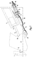
  • Referring first to Figure 1, a jaw crusher comprises a fixed jaw 1 and an oscillating jaw 2 fixed to a jawstock 3. The size of the crushed product is determined by the closest separation of the fixed jaw 1 and the oscillating jaw 2. This distance is known as the crusher setting and is indicated by the arrows D.
    The jawstock 3 is connected to a toggle block 4 by a toggle plate 5, one end of which locates in a jawstock toggle seat 6. The toggle block 4 is mounted on a toggle beam 7.
    The jawstock 3 has a jawstock pivot bracket 8 to which is connected one end of a tension rod assembly. This assembly comprises a piston rod 9 connected to a piston 17 (see Figure 3) housed within a single acting hydraulic cylinder 10, the end of which is connected to a fixed rod 11. The fixed rod 11 passes through a toggle beam pivot bracket 12 which carries a spring cup 13. The end of the fixed rod 11 carries a spring disc 14, a compression spring 15 being mounted about the terminal portion of the fixed rod 11, between the disc 14 and the spring cup 13.
    The effect of the compression spring 15 is to apply tension to the tension rod assembly, and hence to apply tension to hold the toggle plate 5 in place between the toggle block 4 and the jawstock 3. The disc 14 is bushed for sliding movement on the fixed rod 11, the terminal portion of the fixed rod 11 being threaded and carrying nuts 16 by which the position of the disc 14, and hence the compression applied to the spring 15, can be adjusted.
    If, in use, it is desired to increase or reduce the setting D then the toggle block 4 is moved backwards or forwards respectively. Movement of the toggle block 4 is accomplished by means of hydraulic cylinders (not shown in Figure 1) which are mounted on top of the toggle beam 7 within the frame of the crusher.
    Movement of the jawstock 3 to adjust the setting D alters the tension in the spring 15. The tension rod assembly of piston rod 9 and cylinder 10 is intended to provide automatic correction of this.
    Figure 2 shows the hydraulic circuitry controlling the adjustment of the setting D and also the automatic correction of the tension in the tension rod assembly. As indicated above, adjustment of the setting D is carried out by operation of hydraulic cylinders mounted on the toggle beam 7. These cylinders are indicated in Figure 2 by the numerals 21,22 and are attached in a known manner to taper wedges (not shown) which are arranged to slide over each other. Extending the cylinders 21,22 will reduce the setting D, retracting them will increase the setting D.
    The valves to operate the cylinders 10,21,22 are mounted on a 3 station manifold block, and include the following:
  • V1 - AD3E 16 AM solenoid operated directional valve to load the system pressure, and apply pressure to disengage a locking device 16 which is described below. Actuated by a solenoid S1.
  • V2 - solenoid operated directional valve used to supply oil to the tensioning cylinder 10. Actuated by solenoids S2,S3.
  • V3 - solenoid operated directional valve to supply oil to the wedge cylinders 21,22. Actuated by solenoids S4,S5.
  • V4 - Pressure reducing valve to tension the compression spring 15.
  • V5 - counterbalance valve used to hold pressure in the tensioning cylinder 10 when the locking device 16 is released.
  • V6 - double pilot operated check valve to lock pressure on wedge cylinders 21,22.
  • V7 - line mounted flow control valve to adjust speed of wedge cylinders 21,22.
  • V9 - sequence valve to ensure that there is a pressure to the locking device 16 when the wedge cylinders 21,22 are adjusted.
  • M1 - manifold including a relief cartridge V8-used to control the main pressure.
  • As described above, whenever a setting adjustment is carried out, it is necessary to re-set the tension in the tension rod assembly. To achieve this the effective length of the tension rod assembly is changed by moving the piston 17 within the cylinder 10.
    In normal use, the position of the piston 17 within the cylinder 10 is fixed by a locking device 16 which is shown in greater detail in Figure 3. The locking device 16 comprises a cylindrical casing 35 formed integrally with the end of the cylinder 10. A split bush 31 is mounted on the piston rod 9 and is formed on its external surface with a series of wedge-shaped camming surfaces which mate with correspondingly formed surfaces on a second bush 32. The arrangement is such that slight axial movement of the second bush 32 relative to the split bush 31 causes the cam surfaces of the second bush 32 to bear against the corresponding surfaces of the split bush 31 and thereby to urge the split bush 31 into frictional engagement with the piston rod 9. Spring disc washers 33 are mounted about the piston rod 9 and act on the second bush 32 so as to bias it into engagement with the split bush 31, and hence into the locked condition. To release the lock, hydraulic fluid is pumped into an annular chamber 34 where it acts on an unlocking piston 36 which in turn bears against the second bush 32. The action of the unlocking piston 36 causes the second bush 32 to disengage from the split bush 31, and hence releases the split bush 31 from the piston rod 9, allowing the latter to move. When the piston rod 9 has moved to its desired position the fluid pressure in the chamber 34 is released, whereupon the second bush 32 engages the split bush 31, under the action of the disc washers 33, and locks the piston rod 9.
    Correction of the tension in the tension rod assembly is carried out, with the locking device 16 unlocked as described above, by applying hydraulic pressure to one side or other of the cylinder 10. The hydraulic pressure in the cylinder 10 is adjusted by means of the pressure reducing valve V4 and/or the counterbalance valve V5 until it reaches a pre-set value. Once that pre-set value has been reached, the hydraulic pressure to the locking device 16 is released, causing the position of the piston rod 9 and hence the overall length of the tension rod assembly to become fixed.
    The detailed sequence of operations involved in decreasing the crusher setting D (closing the crusher) and increasing the crusher setting D (opening the crusher) will now be described.
    A) Closing the Crusher
    The following solenoids are energised together: S4 and S1.
  • 1. By energising solenoid S1 on valve V1, pressurised oil is supplied to the locking device 16. This unlocks the cylinder 10, as described above.
  • 2. Sequence valve V9 ensures the locking device 16 has received a pressure to unlock it. Without this pressure no other valves will receive pressurised oil.
  • 3. By energising solenoid S4 on valve V3 pressurised oil is directed to the full bore side of wedge cylinders 21,22. These cylinders 21,22 move the toggle block 4 forwards by means of the tapered wedges referred to above, thereby reducing the crusher setting D.
  • 4. As the crusher closes, the tension on the compression spring 15 is increased, this in turn increases the pressure of the oil in the annulus side of the tension cylinder 10. Beyond a certain pressure excess oil is expelled back to tank across valve V5. Thus, the compression spring 15 is kept at its correct tension.
  • B) Opening the Crusher
    The following solenoids are energised together: S5, S1 and S2.
  • 1. By energising solenoid S1 on valve V1, pressurised oil is supplied to the locking device 16. This unlocks the cylinder 10.
  • 2. Sequence valve V9 ensures the locking device 16 has received a pressure to unlock it. Without this pressure no other valves will receive pressurised oil.
  • 3. By energising solenoid S5 on valve V3 pressurised oil is directed to the annulus side of wedge cylinders 21 and 22. These cylinders move the toggle block 4 backwards, by means of the tapered wedges referred to above, thereby increasing the crusher setting D.
  • 4. Simultaneously, solenoid S2 on valve V2 is energised. This allows a pressurised flow of oil (the pressure ofwhich is determined by valve V4 which is adjustable), into the annulus side of the tensioning cylinder 10. As the rod 9 of this cylinder 10 is attached to the crusher jawstock 3, and the jawstock is moving back, the piston in the cylinder 10 is pushed back exactly the correct amount to compensate for the movement of the jawstock 3.
  • When the desired crusher setting D is achieved the solenoids S5, S1 and S2 are de-energised, whereupon:
  • 1. The crusher jawstock 3 stops moving. The double pilot operated check valve V6 locks the pressure in the wedge adjustment cylinders 21,22 to prevent the crusher setting "creeping open" under load.
  • 2. The tension spring 15 is set at the same setting as it was previously, due to valve V4 which has pressurised the annulus side of the cylinder 10 at the same pressure as it had previously.
  • 3. The lock 16 is re-applied the instant solenoid S1 is de-energised. This prevents any creeping of the tensioning cylinder 10 open and thus any loss in tension of the compression spring 15.
  • Claims (9)

    1. A jaw crusher comprising an oscillating jaw (2,3) having an operating setting which is adjustable by means of a toggle device (7) connected to the oscillating jaw (2,3) by a freely supported toggle plate (5), the oscillating jaw (2,3) and the toggle device (7) being connected and held in tension by a tension rod assembly (9,10,11), wherein there are provided means for determining the tension applied to the tension rod assembly (9,10,11), comparing the measured tension with a pre-set value and adjusting the tension to the pre-set value.
    2. A crusher as claimed in Claim 1, wherein the tension rod assembly (9,10,11) is pivotally connected at one end to the oscillating jaw (2,3) and is connected at its other end to a bracket (12) fixed to the toggle device (7).
    3. A crusher as claimed in Claim 2, wherein the tension rod assembly (9,10,11) is tensioned by a compression spring (15) mounted about the assembly (9,10,11) and acting between the bracket (12) and a flange or the like (14) at the end of the assembly (9,10,11).
    4. A crusher as claimed in any preceding claim, wherein the means for adjusting the tension in the tension rod assembly (9,10,11) comprises means for adjusting the effective length of the assembly (9,10,11).
    5. A crusher as claimed in Claim 4, wherein said means for adjusting the effective length of the assembly comprises a fluid driven piston (17) and cylinder (18), the piston (17) and the cylinder (10) being, or forming part of, the tension rod assembly (9,10,11), movement of the piston (17) within the cylinder (10) effectively altering the length of the tension rod assembly (9,10,11).
    6. A crusher as claimed in Claim 5, wherein the piston (17) is hydraulically operated.
    7. A crusher as claimed in Claim 5 or Claim 6, wherein there is provided a locking device (16) for locking the piston (17) in position once the tension in the tension rod assembly (9,10,11) has been adjusted to the desired value.
    8. A crusher as claimed in Claim 7, wherein the locking device (16) comprises a split bush (31) which surrounds the piston rod (9) and a second bush (32) having a cam surface which bears against the split bush (31) to urge the split bush (31) into engagement with the piston rod (9).
    9. A locking device for a movable shaft or rod (9), the locking device comprising a split bush (31) which surrounds the shaft or rod (9) and a second bush (32) movable from a locking position, in which a cam surface of the second bush (32) bears against the split bush (31) so as to urge the split bush (31) into locking engagement with the shaft or rod (9), to an unlocked position in which the split bush (31) is released from the rod or shaft (9).
    EP97306543A 1996-08-28 1997-08-27 Improvements in or relating to crushing machines Withdrawn EP0826421A3 (en)

    Applications Claiming Priority (2)

    Application Number Priority Date Filing Date Title
    GBGB9617917.1A GB9617917D0 (en) 1996-08-28 1996-08-28 Improvements in or relating to crushing machines
    GB9617917 1996-08-28

    Publications (2)

    Publication Number Publication Date
    EP0826421A2 true EP0826421A2 (en) 1998-03-04
    EP0826421A3 EP0826421A3 (en) 1998-06-10

    Family

    ID=10799017

    Family Applications (1)

    Application Number Title Priority Date Filing Date
    EP97306543A Withdrawn EP0826421A3 (en) 1996-08-28 1997-08-27 Improvements in or relating to crushing machines

    Country Status (2)

    Country Link
    EP (1) EP0826421A3 (en)
    GB (1) GB9617917D0 (en)

    Cited By (3)

    * Cited by examiner, † Cited by third party
    Publication number Priority date Publication date Assignee Title
    EP1424132A1 (en) * 2002-11-28 2004-06-02 Komatsu Ltd Jaw crusher with an outlet clearance adjusting mechanism
    US7168644B2 (en) 2002-11-28 2007-01-30 Komatsu Ltd. Jaw crusher and self-propelled crushing machine having the jaw crusher
    JP2009297591A (en) * 2008-06-10 2009-12-24 Rasa Ind Ltd Jaw crusher

    Citations (5)

    * Cited by examiner, † Cited by third party
    Publication number Priority date Publication date Assignee Title
    FR1171849A (en) * 1956-04-24 1959-01-30 Westfalia Dinnendahl Jaw crusher, and more especially with oscillating jaws
    AU461995B2 (en) * 1971-07-09 1975-05-27 Vickers Ruwolt Proprietary Ltd. Remote control adjustment means
    FR2460716A1 (en) * 1979-07-06 1981-01-30 Fives Cail Babcock CRUSHER OR SHREDDER MACHINE WITH ADJUSTMENT AND SAFETY SYSTEM
    US4749132A (en) * 1985-09-10 1988-06-07 Kawasaki Jukogyo Kabushiki Kaisha Method for crushing massive furnace slag using a swingable type crushing apparatus
    US4765546A (en) * 1986-02-24 1988-08-23 Stewart Gerald W Jaw-type crushing apparatus

    Patent Citations (5)

    * Cited by examiner, † Cited by third party
    Publication number Priority date Publication date Assignee Title
    FR1171849A (en) * 1956-04-24 1959-01-30 Westfalia Dinnendahl Jaw crusher, and more especially with oscillating jaws
    AU461995B2 (en) * 1971-07-09 1975-05-27 Vickers Ruwolt Proprietary Ltd. Remote control adjustment means
    FR2460716A1 (en) * 1979-07-06 1981-01-30 Fives Cail Babcock CRUSHER OR SHREDDER MACHINE WITH ADJUSTMENT AND SAFETY SYSTEM
    US4749132A (en) * 1985-09-10 1988-06-07 Kawasaki Jukogyo Kabushiki Kaisha Method for crushing massive furnace slag using a swingable type crushing apparatus
    US4765546A (en) * 1986-02-24 1988-08-23 Stewart Gerald W Jaw-type crushing apparatus

    Cited By (4)

    * Cited by examiner, † Cited by third party
    Publication number Priority date Publication date Assignee Title
    EP1424132A1 (en) * 2002-11-28 2004-06-02 Komatsu Ltd Jaw crusher with an outlet clearance adjusting mechanism
    US7124971B2 (en) 2002-11-28 2006-10-24 Komatsu Ltd. Jaw crusher
    US7168644B2 (en) 2002-11-28 2007-01-30 Komatsu Ltd. Jaw crusher and self-propelled crushing machine having the jaw crusher
    JP2009297591A (en) * 2008-06-10 2009-12-24 Rasa Ind Ltd Jaw crusher

    Also Published As

    Publication number Publication date
    GB9617917D0 (en) 1996-10-09
    EP0826421A3 (en) 1998-06-10

    Similar Documents

    Publication Publication Date Title
    JP3788427B2 (en) Jaw crusher
    CA2516528C (en) Jaw-type rock crusher with toggle plate tension bar
    US6619576B2 (en) Outlet clearance adjustment mechanism of jaw crusher and self-propelled crushing machine loaded with jaw crusher having outlet clearance adjustment mechanism of jaw crusher
    CN103842088B (en) Jaw crusher
    US11826761B2 (en) High-pressure pump
    US4973001A (en) Material bed roller mill
    CA2004531C (en) Rock crushers
    US20210138477A1 (en) Jaw Crusher
    US4765546A (en) Jaw-type crushing apparatus
    US20180071742A1 (en) Jaw crusher systems, methods, and apparatus
    EP0826421A2 (en) Improvements in or relating to crushing machines
    US6022170A (en) Paver
    CA2175879A1 (en) Roll crusher
    JPH09511172A (en) Crushers with jaws specially configured for material recycling
    AU684971B2 (en) Toggle block position adjusting method for a jaw crusher and device for use in the method
    CN101772645B (en) Hydrostatic machine including the adjusting apparatus with control and regulation valve return element
    KR100765853B1 (en) Outlet space auto-controlling apparatus for jaw crusher
    KR102424923B1 (en) Jaw Crusher Hydraulic System with Outlet Clearance and Tension Adjustment
    US5540393A (en) Gyrasphere crusher with bladder operated bowl lock mechanism
    US2784916A (en) Spring relief mechanism for jaw type crushers
    EP1049860B1 (en) Fuel injection pump
    CA1120384A (en) Feed control for horizontal bandsaw machines
    US5878969A (en) Sliding mechanism for a jaw crusher toggle block
    JPH07837A (en) Wedging device for adjusting setting of jaw crusher
    CA1282760C (en) Jaw type crushing apparatus

    Legal Events

    Date Code Title Description
    PUAI Public reference made under article 153(3) epc to a published international application that has entered the european phase

    Free format text: ORIGINAL CODE: 0009012

    AK Designated contracting states

    Kind code of ref document: A2

    Designated state(s): AT BE CH DE DK ES FI FR GB GR IE IT LI LU MC NL PT SE

    AX Request for extension of the european patent

    Free format text: AL;LT;LV;RO;SI

    PUAL Search report despatched

    Free format text: ORIGINAL CODE: 0009013

    AK Designated contracting states

    Kind code of ref document: A3

    Designated state(s): AT BE CH DE DK ES FI FR GB GR IE IT LI LU MC NL PT SE

    AX Request for extension of the european patent

    Free format text: AL;LT;LV;RO;SI

    AKX Designation fees paid
    RBV Designated contracting states (corrected)
    STAA Information on the status of an ep patent application or granted ep patent

    Free format text: STATUS: THE APPLICATION IS DEEMED TO BE WITHDRAWN

    18D Application deemed to be withdrawn

    Effective date: 19981211