EP0825430B1 - Gas monitors - Google Patents
Gas monitors Download PDFInfo
- Publication number
- EP0825430B1 EP0825430B1 EP97305952A EP97305952A EP0825430B1 EP 0825430 B1 EP0825430 B1 EP 0825430B1 EP 97305952 A EP97305952 A EP 97305952A EP 97305952 A EP97305952 A EP 97305952A EP 0825430 B1 EP0825430 B1 EP 0825430B1
- Authority
- EP
- European Patent Office
- Prior art keywords
- source
- monitor
- sensor
- gas
- light
- Prior art date
- Legal status (The legal status is an assumption and is not a legal conclusion. Google has not performed a legal analysis and makes no representation as to the accuracy of the status listed.)
- Expired - Lifetime
Links
- 230000003287 optical effect Effects 0.000 claims description 25
- SGPGESCZOCHFCL-UHFFFAOYSA-N Tilisolol hydrochloride Chemical compound [Cl-].C1=CC=C2C(=O)N(C)C=C(OCC(O)C[NH2+]C(C)(C)C)C2=C1 SGPGESCZOCHFCL-UHFFFAOYSA-N 0.000 claims 1
- 230000005855 radiation Effects 0.000 abstract description 28
- 239000007789 gas Substances 0.000 description 38
- 238000010586 diagram Methods 0.000 description 2
- 239000000463 material Substances 0.000 description 2
- 238000005259 measurement Methods 0.000 description 2
- 238000010521 absorption reaction Methods 0.000 description 1
- XAGFODPZIPBFFR-UHFFFAOYSA-N aluminium Chemical compound [Al] XAGFODPZIPBFFR-UHFFFAOYSA-N 0.000 description 1
- 229910052782 aluminium Inorganic materials 0.000 description 1
- 239000004411 aluminium Substances 0.000 description 1
- 239000011248 coating agent Substances 0.000 description 1
- 238000000576 coating method Methods 0.000 description 1
- 238000009833 condensation Methods 0.000 description 1
- 230000005494 condensation Effects 0.000 description 1
- 230000001419 dependent effect Effects 0.000 description 1
- 239000002360 explosive Substances 0.000 description 1
- 231100001261 hazardous Toxicity 0.000 description 1
- 238000003754 machining Methods 0.000 description 1
- 239000007787 solid Substances 0.000 description 1
- 238000001228 spectrum Methods 0.000 description 1
- 239000000758 substrate Substances 0.000 description 1
Images


Classifications
-
- G—PHYSICS
- G01—MEASURING; TESTING
- G01N—INVESTIGATING OR ANALYSING MATERIALS BY DETERMINING THEIR CHEMICAL OR PHYSICAL PROPERTIES
- G01N21/00—Investigating or analysing materials by the use of optical means, i.e. using sub-millimetre waves, infrared, visible or ultraviolet light
- G01N21/01—Arrangements or apparatus for facilitating the optical investigation
- G01N21/03—Cuvette constructions
- G01N21/031—Multipass arrangements
Definitions
- This invention relates to gas monitors and more particularly to those in which optical radiation is transmitted through a gas and subsequently detected to provide information concerning the gas.
- an infra-red source is arranged to emit radiation which passes through a gas to be monitored. Infra-red radiation is absorbed by the gas and that remaining is subsequently detected by a pyroelectric detector. A comparison is made between the source intensity and the intensity of radiation detected following passage through the gas to give the concentration of the gas.
- an infra-red source is located remote from a pyroelectric detector on a bench with a tube between them through which gas is passed.
- Infra-red radiation travels along a direct path between the source and sensor but there also tend to be multiple rejections from the interior surfaces of the tube. This results in numerous different path lengths taken by the infra-red radiation between the source and the sensor, which leads to errors in measuring the gas concentration. Moreover, the errors vary over time because the interior surfaces of the tube gradually degrade and present a non-uniform surface.
- the present invention seeks to provide a gas monitor having improved characteristics over those previously known.
- a gas monitor comprising an optical source, a sensor sensitive to light from the source, a chamber containing gas to be monitored and reflector means having reflective surfaces in the chamber, the source and sensor being substantially at foci of the reflector means and light being reflected at least three times before reaching the sensor from the source.
- a plurality of folded optical paths are defined between the source and sensor through gas to be monitored, and the paths may be made substantially the same length.
- the optical source is preferably an infra-red source but sources and sensors operating in other parts of the optical spectrum may be used in other embodiments.
- a monitor in accordance with the invention may be used to detect vapour or gas concentration or may be used to provide other information depending on the regime under which it operates.
- the gas monitor is used to determine concentration of a known gas by providing a comparison between the source intensity and intensity of optical radiation detected by the sensor after having been partially absorbed by the gas.
- the reflective surfaces of the reflector means may be discontinuous in two or more discrete sections or present a continuous surface.
- the reflector means includes curved regions and planar regions to provide a compact arrangement.
- the reflective surfaces are defined by interior surfaces of the chamber.
- the chamber may have polished walls or have a reflective coating laid down on it for example.
- the chamber may be fabricated by machining from a solid block of material, for example.
- the invention By employing the invention, radiation travelling from the source to the sensor over different routes can be arranged to travel along the same path length and hence the same amount of absorption occurs, giving an accurate measure of the concentration.
- this provides a particularly compact arrangement whilst giving relatively long optical paths through the gas.
- This makes a monitor in accordance with the invention convenient to use and include in other equipment. It also allows the monitor to be readily incorporated in a housing which can be made safe for use in hazardous environments where, for example, flammable or explosive gases are to be detected.
- the housing is flameproof.
- the source is arranged to heat substantially all the reflective surfaces, the folded configuration allowing this to be readily achieved. This reduces the risk of condensation on optical surfaces which in previously known devices has required a separate heater to be provided.
- the reflective means includes a reflective surface or surfaces having part elliptical section to provide focusing of the optical radiation from the source and onto the sensor.
- the properties of an ellipse or ellipsoid are such that the optical path lengths along different routes between the source and sensor can be made substantially equal.
- the source is located at a focus of a first ellipsoid and the sensor at a focus of a second ellipsoid, and the first and second ellipsoid having a common virtual focus.
- the first and second ellipsoids have substantially the same dimensions.
- focusing of the optical radiation may also be achieved at a point intermediate the source and sensor along the optical path, enabling an accurate measurement of the concentration of the gas to be obtained.
- the reflective means may be thought of as comprising an ellipsoidal surface which is folded back on itself.
- a planar reflective surface may form part of the optical path between the curved surfaces such as those which are part elliptical in section.
- the planar surface need not be located at the mid-point between the foci of either or both ellipses. If it is arranged nearer the source and reflector than the common virtual focus it results in a more compact arrangement than if it were arranged at the mid-point.
- the reflector means includes offset parabolic surfaces to provide focusing at the source and sensor.
- the source and sensor may be located exactly at foci of the reflector means or close to them. Similarly, although complete focusing of the optical radiation at the source and sensor will give more accurate measurements, it may be acceptable to provide a reduced amount of focusing in some circumstances.
- the reflective means, source and sensor may be arranged such that there are only three reflections of light as it travels through the gas between the source and the sensor. In one particular advantageous embodiment however there are five reflections involved, giving long optical paths through the gas.
- a gas monitor 1 comprises a flameproof housing 2 having a cylindrical outer surface with end walls 3 and 4.
- the interior of the housing 2 contains an infra-red source 5 mounted on one of the end walls 4 and a pyroelectric detector 6 also mounted on the end wall 4.
- the interior surface of the housing 2 is of polished aluminium or some other material which reflects infra-red radiation.
- the housing 2 defines a chamber within which gas to be monitored is contained.
- the chamber may be sealed following introduction of the gas but more usually includes an aperture or apertures (not shown) to allow gas to enter and leave the chamber from its surroundings.
- the reflective curved wall 7 in the region of the source 5 is a part ellipse in section with the source 5 being placed at one of its foci.
- the wall 7 is curved in three dimensions to define a part-ellipsoid.
- the sensor 6 is located at a focus defined by the adjacent curved surface 8 which is also part elliptical in section, the reflective surfaces 7 and 8 being continuous and adjacent one another.
- the end wall 3 opposite that on which the source 5 and sensor 6 are mounted has a reflective inner surface which is planar.
- the wall 4 between the source 5 and sensor 6 has a reflective section 9 which is also planar and parallel to the end wall 3.
- the configuration of the reflective surfaces and locations of the source 5 and sensor 6 are such that infra-red radiation emitted from the source 5 in most directions is directed onto the elliptical surface 7. Radiation reflected from the surface 7 is then incident on the planar surface 3 from which it is reflected and focussed on the region 9 between the source 5 and sensor 6. The radiation is then directed onto the elliptical surface 8 via the surface 3 to the detector 6, where it is focussed. Thus the radiation undergoes five reflections before being received at the sensor 6. A wall 10 surrounding the central region 9 reduces the amount of radiation which reaches the sensor 6 directly, without reflection, from the source or via a route other than that described above.
- the housing also includes a reference sensor 11 which is located adjacent to the sensor 6 and used to compensate for changes in operating conditions and with time. Electrical connections to the source 5 and sensors 6 and 11 have been omitted from the Figure. There is an opening (not shown) in the planar surface 3 through which gas to be detected enters the chamber. Although not shown in the embodiment of Figure 1, shielding additional to the wall 10 may be used to further reduce the amount of radiation travelling along paths other than that taken when reflected off the ellipsoidal surfaces.
- Figure 3 is an explanatory diagram in section illustrating the equality of optical path length for light emitted in different directions achievable by employing the invention.
- the parts of the housing are indicated schematically, with the end walls 3 and 4 being shown.
- the part ellipsoidal reflective surfaces 7 and 8 are shown as an unbroken line, the broken line illustrating the form of these surfaces if they were to be continued to form complete ellipsoids.
- the source 5 is located at a focus of an ellipse a which has a second focus 12, which in this case is a virtual focus as the elliptical surface does not continue beyond end wall 3. It is a property of an ellipse that light emitted from one focus is focussed at the second focus.
- the path of optical radiation from the source 5 is shown and, in the absence of the reflective surface 3 and assuming that the ellipse a were continuous, would be focussed at the second focus 12. Because of the intervening planar reflective surface 3, the light is instead focussed at the region 9 which is the same distance along the optical path from the source 5 as the virtual focus 12, region 9 being the same distance from the reflective surface 3 as the second focus 12.
- the sensor 6 is located at a focus of an ellipse b which in this case, and preferably, has the same configuration as ellipse a and is orientated such that it has a virtual focus which coincides with virtual focus 12.
- Light reflected from the focussed region 9 is reflected from planar surface 3 and focussed by the ellipsoidal surface 8 onto the sensor 6. In the absence of the reflective surface 3 and if the ellipse b were complete, then this light would be reflected and focussed at the virtual focus 12.
- the properties of the ellipses ensure that light reflected from the source 5 in a plurality of different directions travels along the same path length before being refocussed at the sensor 6.
- the planar surface 3 may be located such that it is closer to the foci at which the source 5 and sensor 6 are positioned than it is to the virtual focus 12 to provide a more compact arrangement. This will require the reflective surface 9 to be re-positioned relative to the foci at 5 and 6 if it is still wished to obtain focusing of the light at this surface.
- Figure 4 illustrates schematically another gas monitor in which a chamber containing the gas has curved interior surfaces 13 and 14 which define foci at which an infra-red source 15 and sensor 16 are located.
- the curved surfaces 13 and 14 are offset parabolas.
- Planar reflective surfaces 17 and 18 define part of the optical path between the source 15 and sensor 16.
- the curved surfaces 13 and 14 are offset parabolas, there is no focussing of the infra red radiation at the reflective planar surface 18 located on a common substrate with the source 15 and sensor 16, but optical path lengths between the source 15 and sensor 16 are substantially equal for a wide angular spread of emitted radiation.
- three reflections from planar surfaces between two curved surfaces only one reflection occurs at a planar surface. This may be achieved in an off axis parabola arrangement by one parabolic reflective surface being approximately normal to another such surface.
- the monitor illustrated in Figure 1 might be modified by replacing planar region 9 with a part ellipsoidal surface having the sensor at its focus. Light is then reflected three times as it passes through the gas. Other arrangements may involve more than five reflections.
Landscapes
- Physics & Mathematics (AREA)
- Health & Medical Sciences (AREA)
- Life Sciences & Earth Sciences (AREA)
- Chemical & Material Sciences (AREA)
- Analytical Chemistry (AREA)
- Biochemistry (AREA)
- General Health & Medical Sciences (AREA)
- General Physics & Mathematics (AREA)
- Immunology (AREA)
- Pathology (AREA)
- Investigating Or Analysing Materials By Optical Means (AREA)
- Sampling And Sample Adjustment (AREA)
- Investigating Or Analyzing Materials By The Use Of Electric Means (AREA)
- Glass Compositions (AREA)
- Investigating Or Analyzing Materials By The Use Of Fluid Adsorption Or Reactions (AREA)
Abstract
Description
- This invention relates to gas monitors and more particularly to those in which optical radiation is transmitted through a gas and subsequently detected to provide information concerning the gas.
- In one known gas monitor for example EP 0-704-691, an infra-red source is arranged to emit radiation which passes through a gas to be monitored. Infra-red radiation is absorbed by the gas and that remaining is subsequently detected by a pyroelectric detector. A comparison is made between the source intensity and the intensity of radiation detected following passage through the gas to give the concentration of the gas. The concentration is related to the intensity by the following equation:
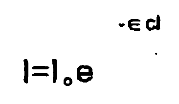
where I is the intensity of radiation detected by the detector, Io is the intensity of radiation emitted at the source, ∈ is effectively a constant which is dependent on the particular gas being monitored, c is the gas concentration and I is the distance travelled by the radiation through the gas. - In one known gas monitor, an infra-red source is located remote from a pyroelectric detector on a bench with a tube between them through which gas is passed. Infra-red radiation travels along a direct path between the source and sensor but there also tend to be multiple rejections from the interior surfaces of the tube. This results in numerous different path lengths taken by the infra-red radiation between the source and the sensor, which leads to errors in measuring the gas concentration. Moreover, the errors vary over time because the interior surfaces of the tube gradually degrade and present a non-uniform surface.
- The present invention seeks to provide a gas monitor having improved characteristics over those previously known.
- According to the invention as defined in
claim 1, there is provided a gas monitor comprising an optical source, a sensor sensitive to light from the source, a chamber containing gas to be monitored and reflector means having reflective surfaces in the chamber, the source and sensor being substantially at foci of the reflector means and light being reflected at least three times before reaching the sensor from the source. - By using the invention, a plurality of folded optical paths are defined between the source and sensor through gas to be monitored, and the paths may be made substantially the same length.
- The optical source is preferably an infra-red source but sources and sensors operating in other parts of the optical spectrum may be used in other embodiments.
- A monitor in accordance with the invention may be used to detect vapour or gas concentration or may be used to provide other information depending on the regime under which it operates. However, typically, the gas monitor is used to determine concentration of a known gas by providing a comparison between the source intensity and intensity of optical radiation detected by the sensor after having been partially absorbed by the gas.
- The reflective surfaces of the reflector means may be discontinuous in two or more discrete sections or present a continuous surface. In a preferred embodiment, the reflector means includes curved regions and planar regions to provide a compact arrangement. Preferably, the reflective surfaces are defined by interior surfaces of the chamber. The chamber may have polished walls or have a reflective coating laid down on it for example. The chamber may be fabricated by machining from a solid block of material, for example.
- By employing the invention, radiation travelling from the source to the sensor over different routes can be arranged to travel along the same path length and hence the same amount of absorption occurs, giving an accurate measure of the concentration. In addition, as the optical paths are folded, this provides a particularly compact arrangement whilst giving relatively long optical paths through the gas. This makes a monitor in accordance with the invention convenient to use and include in other equipment. It also allows the monitor to be readily incorporated in a housing which can be made safe for use in hazardous environments where, for example, flammable or explosive gases are to be detected. Advantageously, for these applications, the housing is flameproof.
- In a preferred embodiment of the invention, the source is arranged to heat substantially all the reflective surfaces, the folded configuration allowing this to be readily achieved. This reduces the risk of condensation on optical surfaces which in previously known devices has required a separate heater to be provided.
- In a particularly advantageous embodiment of the invention, the reflective means includes a reflective surface or surfaces having part elliptical section to provide focusing of the optical radiation from the source and onto the sensor. The properties of an ellipse or ellipsoid are such that the optical path lengths along different routes between the source and sensor can be made substantially equal. In an advantageous embodiment of the invention, the source is located at a focus of a first ellipsoid and the sensor at a focus of a second ellipsoid, and the first and second ellipsoid having a common virtual focus. Preferably, the first and second ellipsoids have substantially the same dimensions. By employing this aspect of the invention, focusing of the optical radiation may also be achieved at a point intermediate the source and sensor along the optical path, enabling an accurate measurement of the concentration of the gas to be obtained. The reflective means may be thought of as comprising an ellipsoidal surface which is folded back on itself.
- A planar reflective surface may form part of the optical path between the curved surfaces such as those which are part elliptical in section. The planar surface need not be located at the mid-point between the foci of either or both ellipses. If it is arranged nearer the source and reflector than the common virtual focus it results in a more compact arrangement than if it were arranged at the mid-point. In another embodiment of the invention, the reflector means includes offset parabolic surfaces to provide focusing at the source and sensor.
- The source and sensor may be located exactly at foci of the reflector means or close to them. Similarly, although complete focusing of the optical radiation at the source and sensor will give more accurate measurements, it may be acceptable to provide a reduced amount of focusing in some circumstances.
- The reflective means, source and sensor may be arranged such that there are only three reflections of light as it travels through the gas between the source and the sensor. In one particular advantageous embodiment however there are five reflections involved, giving long optical paths through the gas.
- Some ways in which the invention may be performed are now described by way of example with reference to the accompanying drawings, in which:
- Figure 1 is a transverse sectional schematic view of a gas monitor in accordance with the invention;
- Figure 2 is a view through II-II on Figure 1;
- Figure 3 is an explanatory schematic diagram relating to the gas monitor of Figure 1;
- Figure 4 illustrates schematically another gas monitor in accordance with the invention.
- With reference to Figures 1 and 2, a
gas monitor 1 comprises aflameproof housing 2 having a cylindrical outer surface withend walls 3 and 4. The interior of thehousing 2 contains an infra-red source 5 mounted on one of theend walls 4 and a pyroelectric detector 6 also mounted on theend wall 4. The interior surface of thehousing 2 is of polished aluminium or some other material which reflects infra-red radiation. - The
housing 2 defines a chamber within which gas to be monitored is contained. The chamber may be sealed following introduction of the gas but more usually includes an aperture or apertures (not shown) to allow gas to enter and leave the chamber from its surroundings. - The reflective
curved wall 7 in the region of the source 5 is a part ellipse in section with the source 5 being placed at one of its foci. Thewall 7 is curved in three dimensions to define a part-ellipsoid. The sensor 6 is located at a focus defined by the adjacentcurved surface 8 which is also part elliptical in section, thereflective surfaces wall 4 between the source 5 and sensor 6 has a reflective section 9 which is also planar and parallel to the end wall 3. - The configuration of the reflective surfaces and locations of the source 5 and sensor 6 are such that infra-red radiation emitted from the source 5 in most directions is directed onto the
elliptical surface 7. Radiation reflected from thesurface 7 is then incident on the planar surface 3 from which it is reflected and focussed on the region 9 between the source 5 and sensor 6. The radiation is then directed onto theelliptical surface 8 via the surface 3 to the detector 6, where it is focussed. Thus the radiation undergoes five reflections before being received at the sensor 6. Awall 10 surrounding the central region 9 reduces the amount of radiation which reaches the sensor 6 directly, without reflection, from the source or via a route other than that described above. - The housing also includes a reference sensor 11 which is located adjacent to the sensor 6 and used to compensate for changes in operating conditions and with time. Electrical connections to the source 5 and sensors 6 and 11 have been omitted from the Figure. There is an opening (not shown) in the planar surface 3 through which gas to be detected enters the chamber. Although not shown in the embodiment of Figure 1, shielding additional to the
wall 10 may be used to further reduce the amount of radiation travelling along paths other than that taken when reflected off the ellipsoidal surfaces. - Figure 3 is an explanatory diagram in section illustrating the equality of optical path length for light emitted in different directions achievable by employing the invention. The parts of the housing are indicated schematically, with the
end walls 3 and 4 being shown. The part ellipsoidalreflective surfaces - The sensor 6 is located at a focus of an ellipse b which in this case, and preferably, has the same configuration as ellipse a and is orientated such that it has a virtual focus which coincides with virtual focus 12. Light reflected from the focussed region 9 is reflected from planar surface 3 and focussed by the
ellipsoidal surface 8 onto the sensor 6. In the absence of the reflective surface 3 and if the ellipse b were complete, then this light would be reflected and focussed at the virtual focus 12. The properties of the ellipses ensure that light reflected from the source 5 in a plurality of different directions travels along the same path length before being refocussed at the sensor 6. The planar surface 3 may be located such that it is closer to the foci at which the source 5 and sensor 6 are positioned than it is to the virtual focus 12 to provide a more compact arrangement. This will require the reflective surface 9 to be re-positioned relative to the foci at 5 and 6 if it is still wished to obtain focusing of the light at this surface. - Although the above explanation given with reference to Figure 3 is in relation to a two-dimensional section through the ellipsoidal surfaces, the reflective surfaces are three-dimensional and similar considerations apply to other sections through them.
- Figure 4 illustrates schematically another gas monitor in which a chamber containing the gas has curved
interior surfaces sensor 16 are located. In this embodiment, thecurved surfaces reflective surfaces sensor 16. As thecurved surfaces planar surface 18 located on a common substrate with the source 15 andsensor 16, but optical path lengths between the source 15 andsensor 16 are substantially equal for a wide angular spread of emitted radiation. - Although the above described embodiments each involve light being reflected five times as it travels between the source and sensor, in other examples only three or four reflections are involved. For example, instead of having three reflections from planar surfaces between two curved surfaces, only one reflection occurs at a planar surface. This may be achieved in an off axis parabola arrangement by one parabolic reflective surface being approximately normal to another such surface. In another device, the monitor illustrated in Figure 1 might be modified by replacing planar region 9 with a part ellipsoidal surface having the sensor at its focus. Light is then reflected three times as it passes through the gas. Other arrangements may involve more than five reflections.
Claims (14)
- A gas monitor comprising an optical source (5, 15), a sensor (6, 16) sensitive to light from the source (5, 15), a chamber (2) containing gas to be monitored and reflector means having reflective surfaces (3, 4, 7, 8, 9, 13, 14, 17, 18) in the chamber (3) light being reflected at least three times before reaching the sensor (6, 16) from the source (5, 15), characterised in that the source (5, 15) and sensor (6, 16) are substantially at foci of the reflector means and whereby light emitted from the source over an angular spread travels path lengths between the source and the sensor that are substantially equal.
- A monitor as claimed in claim 1 wherein the reflector means comprises curved surfaces (7, 8, 13, 14) defining the foci at which the source (5, 15) and sensor (6, 16) are located and a planar reflective surface defining part of an optical path between them.
- A monitor as claimed in daim 2 wherein light from the source (5, 15) undergoes a first reflection at a curved surface (7, 13), then three reflections at planar surfaces (3, 9, 17, 18) followed by a reflection at a curved surface (8, 14).
- A monitor as claimed in claim 1, 2 or 3 wherein the source (5) and sensor (6) are mounted on a common wall (4) of the chamber (2).
- A monitor as claimed in claim 1, 2, 3 or 4 wherein the reflector means substantially defines a third focus (9) between the foci at which the source and sensor are located.
- A monitor as claimed in any preceding claim wherein the reflective surfaces indude a surface or surfaces (7,8) having a part elliptical section.
- A monitor as daimed in claim 6 wherein the source (5) is at a focus of a first part ellipsoidal surface (7) and the sensor (6) is at a focus of a second part ellipsoidal surface (8) and the first and second ellipsoids (7, 8) share a common virtual focus (12).
- A monitor as claimed in claim 7 wherein the first and second ellipsoids (7, 8) have substantially the same dimensions.
- A monitor as claimed in claim 1, 2, 3 or 4 wherein the reflector means includes two off axis parabolas (13, 14).
- A gas monitor as claimed in any preceding claim wherein the source (5, 15) and sensor (6, 16) are contained within a flameproof housing (2).
- A monitor as claimed in any preceding claim and including an optical shield (10) to reduce the amount of light reaching the sensor from the source via routes other than those which are desired.
- A monitor as claimed in any preceding claim wherein the source (5, 15) is arranged to heat substantially all the surfaces from which light is reflected to a temperature above ambient temperature.
- A monitor as claimed in any preceding claim wherein the optical source (5, 15) is an infra-red source.
- A monitor as claimed in any preceding claim wherein reflective surfaces are defined by interior surfaces (3, 7, 8, 9, 13, 14, 17, 18) of the chamber (2).
Applications Claiming Priority (2)
| Application Number | Priority Date | Filing Date | Title |
|---|---|---|---|
| GB9616809 | 1996-08-10 | ||
| GBGB9616809.1A GB9616809D0 (en) | 1996-08-10 | 1996-08-10 | Gas monitors |
Publications (3)
| Publication Number | Publication Date |
|---|---|
| EP0825430A2 EP0825430A2 (en) | 1998-02-25 |
| EP0825430A3 EP0825430A3 (en) | 1998-08-19 |
| EP0825430B1 true EP0825430B1 (en) | 2006-03-29 |
Family
ID=10798302
Family Applications (1)
| Application Number | Title | Priority Date | Filing Date |
|---|---|---|---|
| EP97305952A Expired - Lifetime EP0825430B1 (en) | 1996-08-10 | 1997-08-05 | Gas monitors |
Country Status (7)
| Country | Link |
|---|---|
| US (1) | US5973326A (en) |
| EP (1) | EP0825430B1 (en) |
| AT (1) | ATE322006T1 (en) |
| CA (1) | CA2212432C (en) |
| DE (1) | DE69735574T2 (en) |
| GB (2) | GB9616809D0 (en) |
| ZA (1) | ZA976936B (en) |
Cited By (1)
| Publication number | Priority date | Publication date | Assignee | Title |
|---|---|---|---|---|
| DE102018215587A1 (en) * | 2018-09-13 | 2020-03-19 | Osram Opto Semiconductors Gmbh | RADIO-CONDUCTING CAVITY STRUCTURE, GAS SENSOR AND METHOD FOR PRODUCING THE SAME |
Families Citing this family (56)
| Publication number | Priority date | Publication date | Assignee | Title |
|---|---|---|---|---|
| SE506942C2 (en) * | 1996-08-28 | 1998-03-02 | Hans Goeran Evald Martin | Gas sensor |
| SE521415C2 (en) * | 1998-02-17 | 2003-10-28 | Hans Goeran Evald Martin | Method for producing a gas sensor-associated detector, as well as a detector made according to the method |
| US6190327B1 (en) * | 1999-05-05 | 2001-02-20 | Nonin Medical, Inc. | Disposable airway adapter for use with a carbon dioxide detector |
| US6876305B2 (en) * | 1999-12-08 | 2005-04-05 | Gentex Corporation | Compact particle sensor |
| US6534769B1 (en) | 1999-12-31 | 2003-03-18 | Ge Medical Systems Information Technologies, Inc. | Low cost main stream gas analyzer system |
| SE522941C2 (en) * | 2000-04-26 | 2004-03-16 | Senseair Ab | gas cell |
| DE10058469C1 (en) * | 2000-11-24 | 2002-05-02 | Draeger Safety Ag & Co Kgaa | Robust, compact optical gas sensor, comprises reflective annular chamber promoting long, multiply-reflected circumferential beam path |
| GB2372099B (en) | 2001-02-08 | 2003-11-05 | Status Scient Controls Ltd | Gas sensor |
| DE10131724B4 (en) * | 2001-06-29 | 2007-10-18 | Dräger Safety AG & Co. KGaA | Optical absorption measuring device |
| DE20301081U1 (en) * | 2002-05-24 | 2003-04-10 | Dräger Safety AG & Co. KGaA, 23560 Lübeck | Optical gas sensor |
| GB2389177B (en) * | 2002-05-31 | 2006-03-15 | Marconi Applied Techn Ltd | Gas sensors |
| SE524900C2 (en) * | 2002-07-22 | 2004-10-19 | Senseair Ab | Gas analyzing arrangements |
| GB2392976A (en) * | 2002-09-13 | 2004-03-17 | Delphi Tech Inc | An optical measuring cell with total internal reflection |
| GB2395259A (en) * | 2002-11-07 | 2004-05-19 | E2V Tech Uk Ltd | Gas sensor with predetermined optical paths between its different detectors |
| SE524663C2 (en) * | 2003-01-15 | 2004-09-14 | Senseair Ab | Gas cell, included in gas sensor for spectral analysis |
| AU2003251361A1 (en) * | 2003-07-28 | 2005-02-25 | Status Scientific Controls Limited | Gas detector |
| GB0327931D0 (en) | 2003-12-02 | 2004-01-07 | City Tech | Gas sensor |
| WO2005057188A1 (en) * | 2003-12-12 | 2005-06-23 | Elt Inc. | Gas sensor |
| KR100494103B1 (en) * | 2003-12-12 | 2005-06-10 | (주)이엘티 | Optical gas sensor |
| DE10360215A1 (en) | 2003-12-20 | 2005-07-28 | Robert Bosch Gmbh | gas sensor |
| DE102004007946A1 (en) * | 2004-02-18 | 2005-09-15 | Tyco Electronics Raychem Gmbh | Gas sensor arrangement in integrated design |
| US20090284745A1 (en) * | 2004-10-18 | 2009-11-19 | Seung-Hwan Yi | Gas cell using two parabolic concave mirrors and method of producing gas sensor using the same |
| JP2006275980A (en) * | 2005-03-30 | 2006-10-12 | Denso Corp | Infrared gas detector |
| KR100576541B1 (en) * | 2005-06-16 | 2006-05-03 | (주) 인바이런먼트 리딩 테크놀러지 | Optical cavity for non-dispersive infrared gas sensor |
| US7717294B2 (en) | 2005-06-20 | 2010-05-18 | South-Tek Systems | Beverage dispensing gas consumption detection with alarm and backup operation |
| DE102005031857B8 (en) * | 2005-06-23 | 2006-11-16 | GfG Ges. für Gerätebau mbH | Optical analyzer |
| DE102005055860B3 (en) * | 2005-11-23 | 2007-05-10 | Tyco Electronics Raychem Gmbh | Gas sensor arrangement with light channel in the form of a conical section rotational body |
| DE102006002870B3 (en) * | 2006-01-19 | 2007-06-28 | Tyco Electronics Raychem Gmbh | Gas sensor for e.g. motor vehicle air conditioner, has holder fixing lamp body of light source in play free and stationary manner, where holder is formed by setting adhesive suppressed in fluid condition against lamp body |
| US8117897B2 (en) * | 2006-11-27 | 2012-02-21 | Applied Nanotech Holdings, Inc. | Elliptical photo-acoustic sensor |
| GB0705356D0 (en) | 2007-03-21 | 2007-04-25 | Alphasense Ltd | Optical absorption gas sensor |
| GB2449433B (en) | 2007-05-21 | 2009-12-09 | Clairair Ltd | Optical gas sensor |
| FR2932567B1 (en) * | 2008-06-11 | 2010-08-13 | Oldham | MEASURING CELL FOR APPARATUS FOR DETECTING THE PRESENCE OF A GAS IN AN ATMOSPHERE |
| DE102009031694B3 (en) * | 2009-07-04 | 2010-10-14 | Qundis Gmbh | Flow Meter |
| GB201000756D0 (en) | 2010-01-18 | 2010-03-03 | Gas Sensing Solutions Ltd | Gas sensor with radiation guide |
| TW201200858A (en) * | 2010-06-28 | 2012-01-01 | Unimems Mfg Co Ltd | A photoelectric gas sensor device and manufacturing method therefor |
| ITMI20130478A1 (en) | 2013-03-29 | 2014-09-30 | N E T Srl | OPTICAL GAS DETECTOR WITH VARIABLE GEOMETRY |
| JP6134207B2 (en) * | 2013-06-07 | 2017-05-24 | アズビル株式会社 | Gas detector |
| KR101581341B1 (en) * | 2014-02-03 | 2015-12-31 | 한국교통대학교산학협력단 | Optical wave guide having multiple independent optical path and Optical Gas Sensor using that |
| CN103954577B (en) * | 2014-05-11 | 2016-03-30 | 西安安通测控技术有限公司 | A kind of miniature infrared gas detection sensor |
| FR3048084A1 (en) * | 2016-02-18 | 2017-08-25 | Commissariat Energie Atomique | NON-DISPERSIVE INFRARED SENSOR FOR DETECTING GAS. |
| KR20180021956A (en) * | 2016-08-22 | 2018-03-06 | (주)트루아이즈 | Optical wave guide using parabolic reflectors and an Infrared gas sensor containing the same |
| FR3057363B1 (en) * | 2016-10-11 | 2019-05-24 | Commissariat A L'energie Atomique Et Aux Energies Alternatives | OPTICAL CAVITY PENDULUM WITH STRONG FOLDING. |
| US10161859B2 (en) | 2016-10-27 | 2018-12-25 | Honeywell International Inc. | Planar reflective ring |
| KR102531308B1 (en) * | 2017-05-30 | 2023-05-10 | 아나로그 디바이시즈 인코포레이티드 | Compact optical gas detection system and device |
| US11788942B2 (en) | 2017-12-15 | 2023-10-17 | Analog Devices, Inc. | Compact optical smoke detector system and apparatus |
| US11079321B2 (en) * | 2018-09-28 | 2021-08-03 | Stmicroelectronics S.R.L. | NDIR detector device for detecting gases having an infrared absorption spectrum |
| US11073467B2 (en) * | 2018-09-28 | 2021-07-27 | Stmicroelectronics S.R.L. | Miniaturized optical particle detector |
| US12211370B2 (en) | 2018-12-02 | 2025-01-28 | Analog Devices, Inc. | Fire detection system |
| US11150130B2 (en) | 2019-03-04 | 2021-10-19 | Si-Ware Systems | Compact multi-pass gas cell for multi-gas spectral sensors |
| US11796445B2 (en) | 2019-05-15 | 2023-10-24 | Analog Devices, Inc. | Optical improvements to compact smoke detectors, systems and apparatus |
| US11747272B2 (en) | 2019-06-10 | 2023-09-05 | Analog Devices, Inc. | Gas detection using differential path length measurement |
| US11821836B2 (en) | 2020-07-13 | 2023-11-21 | Analog Devices, Inc. | Fully compensated optical gas sensing system and apparatus |
| CN112649389B (en) * | 2020-12-07 | 2022-03-08 | 珠海格力电器股份有限公司 | Sensor optical path component, gas sensor, measuring method and air conditioning system |
| CN112649387A (en) * | 2020-12-07 | 2021-04-13 | 珠海格力电器股份有限公司 | Air chamber assembly, gas concentration sensor and air conditioning system |
| CN116981930A (en) * | 2020-12-09 | 2023-10-31 | 尼诺克斯医疗有限公司 | Systems and methods for measuring component concentration |
| CN113484267B (en) * | 2021-06-11 | 2022-07-29 | 汉威科技集团股份有限公司 | Infrared gas sensor based on silicon-based multiple reflection cavity |
Family Cites Families (11)
| Publication number | Priority date | Publication date | Assignee | Title |
|---|---|---|---|---|
| ZA726258B (en) * | 1972-09-13 | 1973-11-28 | Anglo Amer Corp South Africa | Fire detector |
| GB1470381A (en) * | 1973-03-30 | 1977-04-14 | Mullard Ltd | Absorption measurement apparatus for analysing internal com bustion engine exhaust gas |
| US3911277A (en) * | 1974-07-25 | 1975-10-07 | Beckman Instruments Inc | Dual lighthouse detector |
| US4266219A (en) * | 1978-09-18 | 1981-05-05 | Baker Industries, Inc. | Supervisory control system for a smoke detector |
| EP0112347B1 (en) * | 1982-06-25 | 1988-11-23 | OEHLER, Oscar, Dr. | Light collector device and utilization thereof for spectroscopy |
| DE3830906A1 (en) * | 1988-09-10 | 1990-03-15 | Draegerwerk Ag | MIRROR ARRANGEMENT FOR A RADIATION IN A MULTIPLE REFLECTION MEASURING CELL |
| SE462934B (en) * | 1989-05-19 | 1990-09-17 | Opsis Ab Ideon | DEVICE FOR TRANSMISSION AND RECEIVING LIGHTS |
| JP2895622B2 (en) * | 1989-09-29 | 1999-05-24 | アトミック エナジィ オブ カナダ リミテッド | Gas detector using infrared |
| GB2245058A (en) * | 1990-05-18 | 1991-12-18 | Sieger Ltd | A gas detector |
| US5440127A (en) * | 1993-05-17 | 1995-08-08 | Simco/Ramic Corporation | Method and apparatus for illuminating target specimens in inspection systems |
| DE4434814A1 (en) * | 1994-09-29 | 1996-04-04 | Microparts Gmbh | Infrared spectrometric sensor for gases |
-
1996
- 1996-08-10 GB GBGB9616809.1A patent/GB9616809D0/en active Pending
-
1997
- 1997-08-04 GB GB9716355A patent/GB2316172B/en not_active Expired - Lifetime
- 1997-08-04 ZA ZA9706936A patent/ZA976936B/en unknown
- 1997-08-05 DE DE69735574T patent/DE69735574T2/en not_active Expired - Lifetime
- 1997-08-05 US US08/906,090 patent/US5973326A/en not_active Expired - Lifetime
- 1997-08-05 AT AT97305952T patent/ATE322006T1/en not_active IP Right Cessation
- 1997-08-05 EP EP97305952A patent/EP0825430B1/en not_active Expired - Lifetime
- 1997-08-06 CA CA002212432A patent/CA2212432C/en not_active Expired - Lifetime
Cited By (2)
| Publication number | Priority date | Publication date | Assignee | Title |
|---|---|---|---|---|
| DE102018215587A1 (en) * | 2018-09-13 | 2020-03-19 | Osram Opto Semiconductors Gmbh | RADIO-CONDUCTING CAVITY STRUCTURE, GAS SENSOR AND METHOD FOR PRODUCING THE SAME |
| US11867617B2 (en) | 2018-09-13 | 2024-01-09 | Osram Oled Gmbh | Beam conducting cavity structure, gas sensor and method for production thereof |
Also Published As
| Publication number | Publication date |
|---|---|
| GB2316172A (en) | 1998-02-18 |
| DE69735574D1 (en) | 2006-05-18 |
| GB9716355D0 (en) | 1997-10-08 |
| CA2212432A1 (en) | 1998-02-10 |
| CA2212432C (en) | 2007-07-17 |
| EP0825430A2 (en) | 1998-02-25 |
| ZA976936B (en) | 1998-02-18 |
| GB2316172B (en) | 2000-03-22 |
| ATE322006T1 (en) | 2006-04-15 |
| DE69735574T2 (en) | 2007-04-05 |
| US5973326A (en) | 1999-10-26 |
| EP0825430A3 (en) | 1998-08-19 |
| GB9616809D0 (en) | 1996-09-25 |
Similar Documents
| Publication | Publication Date | Title |
|---|---|---|
| CA2212432C (en) | Gas monitors | |
| US5696379A (en) | Measuring apparatus for measuring the concentration of gases utilizing infrared absorption | |
| US5092342A (en) | Sensor arrangement for optically measuring gas components | |
| US6097034A (en) | Radiation source assembly and transducer for analyzing gases or other substances | |
| US7880886B2 (en) | Gas sensor | |
| US5923035A (en) | Infrared absorption measuring device | |
| US4499378A (en) | Infrared radiation gas analyzer | |
| US5255073A (en) | Apparatus for emitting and receiving light | |
| EP1566626B1 (en) | Gas sensor arrangement in an integrated construction | |
| WO2000005570A1 (en) | Hydrogen gas and temperature fiber optic sensor system | |
| US4855718A (en) | Fire detection system employing at least one optical waveguide | |
| US5241367A (en) | Device for measuring the composition of fluids, in particular the components of exhaust gases from internal combustion engines | |
| GB2391309A (en) | Optical gas sensor | |
| US4772124A (en) | Probe for a radiometer | |
| KR20010110748A (en) | Analysis apparatus | |
| US8184774B2 (en) | Dual-color pyrometric measurement of X-ray focal spot temperature | |
| JPS6312938A (en) | Gas analyzer and gas analyzing method | |
| US3471698A (en) | Infrared detection of surface contamination | |
| EP0862734A1 (en) | Improvements in or relating to gas sensors | |
| US5956138A (en) | Multiple-zone emission spectra collection | |
| EP0538031A2 (en) | Method and device for detecting an interface | |
| JPS58143242A (en) | Detector for leaking gas | |
| GB2183821A (en) | A temperature sensor | |
| Zur et al. | Fiber optic distributed thermal sensor | |
| US6509968B1 (en) | Spectroscopic detection |
Legal Events
| Date | Code | Title | Description |
|---|---|---|---|
| PUAI | Public reference made under article 153(3) epc to a published international application that has entered the european phase |
Free format text: ORIGINAL CODE: 0009012 |
|
| AK | Designated contracting states |
Kind code of ref document: A2 Designated state(s): AT BE CH DE ES FI FR IE IT LI NL SE |
|
| AX | Request for extension of the european patent |
Free format text: AL;LT;LV;RO;SI |
|
| PUAL | Search report despatched |
Free format text: ORIGINAL CODE: 0009013 |
|
| AK | Designated contracting states |
Kind code of ref document: A3 Designated state(s): AT BE CH DE DK ES FI FR GB GR IE IT LI LU MC NL PT SE |
|
| AX | Request for extension of the european patent |
Free format text: AL;LT;LV;RO;SI |
|
| AKX | Designation fees paid |
Free format text: AT BE CH DE ES FI FR IE IT LI NL SE |
|
| RBV | Designated contracting states (corrected) |
Designated state(s): AT BE CH DE ES FI FR IE IT LI NL SE |
|
| 17P | Request for examination filed |
Effective date: 19990224 |
|
| R17P | Request for examination filed (corrected) |
Effective date: 19990219 |
|
| RBV | Designated contracting states (corrected) |
Designated state(s): AT BE CH DE ES FI FR IE IT LI NL SE |
|
| 17Q | First examination report despatched |
Effective date: 20040408 |
|
| RAP1 | Party data changed (applicant data changed or rights of an application transferred) |
Owner name: E2V TECHNOLOGIES (UK) LIMITED |
|
| GRAP | Despatch of communication of intention to grant a patent |
Free format text: ORIGINAL CODE: EPIDOSNIGR1 |
|
| GRAS | Grant fee paid |
Free format text: ORIGINAL CODE: EPIDOSNIGR3 |
|
| GRAA | (expected) grant |
Free format text: ORIGINAL CODE: 0009210 |
|
| AK | Designated contracting states |
Kind code of ref document: B1 Designated state(s): AT BE CH DE ES FI FR IE IT LI NL SE |
|
| PG25 | Lapsed in a contracting state [announced via postgrant information from national office to epo] |
Ref country code: NL Free format text: LAPSE BECAUSE OF FAILURE TO SUBMIT A TRANSLATION OF THE DESCRIPTION OR TO PAY THE FEE WITHIN THE PRESCRIBED TIME-LIMIT Effective date: 20060329 Ref country code: LI Free format text: LAPSE BECAUSE OF FAILURE TO SUBMIT A TRANSLATION OF THE DESCRIPTION OR TO PAY THE FEE WITHIN THE PRESCRIBED TIME-LIMIT Effective date: 20060329 Ref country code: CH Free format text: LAPSE BECAUSE OF FAILURE TO SUBMIT A TRANSLATION OF THE DESCRIPTION OR TO PAY THE FEE WITHIN THE PRESCRIBED TIME-LIMIT Effective date: 20060329 Ref country code: BE Free format text: LAPSE BECAUSE OF FAILURE TO SUBMIT A TRANSLATION OF THE DESCRIPTION OR TO PAY THE FEE WITHIN THE PRESCRIBED TIME-LIMIT Effective date: 20060329 Ref country code: AT Free format text: LAPSE BECAUSE OF FAILURE TO SUBMIT A TRANSLATION OF THE DESCRIPTION OR TO PAY THE FEE WITHIN THE PRESCRIBED TIME-LIMIT Effective date: 20060329 |
|
| REG | Reference to a national code |
Ref country code: CH Ref legal event code: EP |
|
| REG | Reference to a national code |
Ref country code: IE Ref legal event code: FG4D |
|
| REF | Corresponds to: |
Ref document number: 69735574 Country of ref document: DE Date of ref document: 20060518 Kind code of ref document: P |
|
| PG25 | Lapsed in a contracting state [announced via postgrant information from national office to epo] |
Ref country code: SE Free format text: LAPSE BECAUSE OF FAILURE TO SUBMIT A TRANSLATION OF THE DESCRIPTION OR TO PAY THE FEE WITHIN THE PRESCRIBED TIME-LIMIT Effective date: 20060629 |
|
| PG25 | Lapsed in a contracting state [announced via postgrant information from national office to epo] |
Ref country code: ES Free format text: LAPSE BECAUSE OF FAILURE TO SUBMIT A TRANSLATION OF THE DESCRIPTION OR TO PAY THE FEE WITHIN THE PRESCRIBED TIME-LIMIT Effective date: 20060710 |
|
| PG25 | Lapsed in a contracting state [announced via postgrant information from national office to epo] |
Ref country code: IE Free format text: LAPSE BECAUSE OF NON-PAYMENT OF DUE FEES Effective date: 20060808 |
|
| REG | Reference to a national code |
Ref country code: CH Ref legal event code: PL |
|
| NLV1 | Nl: lapsed or annulled due to failure to fulfill the requirements of art. 29p and 29m of the patents act | ||
| ET | Fr: translation filed | ||
| PLBE | No opposition filed within time limit |
Free format text: ORIGINAL CODE: 0009261 |
|
| STAA | Information on the status of an ep patent application or granted ep patent |
Free format text: STATUS: NO OPPOSITION FILED WITHIN TIME LIMIT |
|
| 26N | No opposition filed |
Effective date: 20070102 |
|
| PG25 | Lapsed in a contracting state [announced via postgrant information from national office to epo] |
Ref country code: FI Free format text: LAPSE BECAUSE OF FAILURE TO SUBMIT A TRANSLATION OF THE DESCRIPTION OR TO PAY THE FEE WITHIN THE PRESCRIBED TIME-LIMIT Effective date: 20060329 |
|
| PGFP | Annual fee paid to national office [announced via postgrant information from national office to epo] |
Ref country code: IT Payment date: 20120811 Year of fee payment: 16 |
|
| REG | Reference to a national code |
Ref country code: DE Ref legal event code: R082 Ref document number: 69735574 Country of ref document: DE Representative=s name: MANITZ, FINSTERWALD & PARTNER GBR, DE |
|
| REG | Reference to a national code |
Ref country code: DE Ref legal event code: R082 Ref document number: 69735574 Country of ref document: DE Representative=s name: MANITZ FINSTERWALD PATENTANWAELTE PARTMBB, DE Effective date: 20130412 Ref country code: DE Ref legal event code: R082 Ref document number: 69735574 Country of ref document: DE Representative=s name: MANITZ, FINSTERWALD & PARTNER GBR, DE Effective date: 20130412 Ref country code: DE Ref legal event code: R081 Ref document number: 69735574 Country of ref document: DE Owner name: SGX SENSORTECH (IS) LTD., GB Free format text: FORMER OWNER: E2V TECHNOLOGIES (UK) LTD., CHELMSFORD, ESSEX, GB Effective date: 20130412 Ref country code: DE Ref legal event code: R081 Ref document number: 69735574 Country of ref document: DE Owner name: SGX SENSORTECH (IS) LTD., GB Free format text: FORMER OWNER: E2V TECHNOLOGIES (UK) LTD., CHELMSFORD, GB Effective date: 20130412 |
|
| REG | Reference to a national code |
Ref country code: FR Ref legal event code: TP Owner name: SGX SENSORTECH (IS) LIMITED, GB Effective date: 20130507 |
|
| PG25 | Lapsed in a contracting state [announced via postgrant information from national office to epo] |
Ref country code: IT Free format text: LAPSE BECAUSE OF NON-PAYMENT OF DUE FEES Effective date: 20130805 |
|
| REG | Reference to a national code |
Ref country code: FR Ref legal event code: PLFP Year of fee payment: 20 |
|
| PGFP | Annual fee paid to national office [announced via postgrant information from national office to epo] |
Ref country code: DE Payment date: 20160822 Year of fee payment: 20 |
|
| PGFP | Annual fee paid to national office [announced via postgrant information from national office to epo] |
Ref country code: FR Payment date: 20160822 Year of fee payment: 20 |
|
| REG | Reference to a national code |
Ref country code: DE Ref legal event code: R071 Ref document number: 69735574 Country of ref document: DE |