EP0824984B1 - Process and device for driving rotating cropping shears - Google Patents
Process and device for driving rotating cropping shears Download PDFInfo
- Publication number
- EP0824984B1 EP0824984B1 EP97113088A EP97113088A EP0824984B1 EP 0824984 B1 EP0824984 B1 EP 0824984B1 EP 97113088 A EP97113088 A EP 97113088A EP 97113088 A EP97113088 A EP 97113088A EP 0824984 B1 EP0824984 B1 EP 0824984B1
- Authority
- EP
- European Patent Office
- Prior art keywords
- shears
- speed
- gear
- drive motor
- acceleration
- Prior art date
- Legal status (The legal status is an assumption and is not a legal conclusion. Google has not performed a legal analysis and makes no representation as to the accuracy of the status listed.)
- Expired - Lifetime
Links
- 238000000034 method Methods 0.000 title claims description 7
- 230000001133 acceleration Effects 0.000 claims abstract description 32
- 238000005520 cutting process Methods 0.000 claims abstract description 16
- 238000005096 rolling process Methods 0.000 claims description 34
- 230000005540 biological transmission Effects 0.000 claims description 14
- 230000008878 coupling Effects 0.000 claims description 11
- 238000010168 coupling process Methods 0.000 claims description 11
- 238000005859 coupling reaction Methods 0.000 claims description 11
- 238000012544 monitoring process Methods 0.000 claims description 6
- 229910000831 Steel Inorganic materials 0.000 claims 2
- 238000005259 measurement Methods 0.000 claims 2
- 239000010959 steel Substances 0.000 claims 2
- 230000008030 elimination Effects 0.000 claims 1
- 238000003379 elimination reaction Methods 0.000 claims 1
- 230000002349 favourable effect Effects 0.000 claims 1
- 230000001105 regulatory effect Effects 0.000 claims 1
- 238000010586 diagram Methods 0.000 description 8
- 230000002093 peripheral effect Effects 0.000 description 3
- 230000007257 malfunction Effects 0.000 description 2
- 238000007668 thin rolling process Methods 0.000 description 2
- 241001136792 Alle Species 0.000 description 1
- 238000002372 labelling Methods 0.000 description 1
- 238000012806 monitoring device Methods 0.000 description 1
- 238000000926 separation method Methods 0.000 description 1
- 230000035939 shock Effects 0.000 description 1
- 210000002023 somite Anatomy 0.000 description 1
- 230000001960 triggered effect Effects 0.000 description 1
- 230000000007 visual effect Effects 0.000 description 1
Images


Classifications
-
- B—PERFORMING OPERATIONS; TRANSPORTING
- B23—MACHINE TOOLS; METAL-WORKING NOT OTHERWISE PROVIDED FOR
- B23D—PLANING; SLOTTING; SHEARING; BROACHING; SAWING; FILING; SCRAPING; LIKE OPERATIONS FOR WORKING METAL BY REMOVING MATERIAL, NOT OTHERWISE PROVIDED FOR
- B23D36/00—Control arrangements specially adapted for machines for shearing or similar cutting, or for sawing, stock which the latter is travelling otherwise than in the direction of the cut
- B23D36/0008—Control arrangements specially adapted for machines for shearing or similar cutting, or for sawing, stock which the latter is travelling otherwise than in the direction of the cut for machines with only one cutting, sawing, or shearing devices
- B23D36/0033—Control arrangements specially adapted for machines for shearing or similar cutting, or for sawing, stock which the latter is travelling otherwise than in the direction of the cut for machines with only one cutting, sawing, or shearing devices for obtaining pieces of a predetermined length
- B23D36/0058—Control arrangements specially adapted for machines for shearing or similar cutting, or for sawing, stock which the latter is travelling otherwise than in the direction of the cut for machines with only one cutting, sawing, or shearing devices for obtaining pieces of a predetermined length the tool stopping for a considerable time after each cutting operation
-
- B—PERFORMING OPERATIONS; TRANSPORTING
- B23—MACHINE TOOLS; METAL-WORKING NOT OTHERWISE PROVIDED FOR
- B23D—PLANING; SLOTTING; SHEARING; BROACHING; SAWING; FILING; SCRAPING; LIKE OPERATIONS FOR WORKING METAL BY REMOVING MATERIAL, NOT OTHERWISE PROVIDED FOR
- B23D25/00—Machines or arrangements for shearing stock while the latter is travelling otherwise than in the direction of the cut
- B23D25/12—Shearing machines with blades on coacting rotating drums
-
- Y—GENERAL TAGGING OF NEW TECHNOLOGICAL DEVELOPMENTS; GENERAL TAGGING OF CROSS-SECTIONAL TECHNOLOGIES SPANNING OVER SEVERAL SECTIONS OF THE IPC; TECHNICAL SUBJECTS COVERED BY FORMER USPC CROSS-REFERENCE ART COLLECTIONS [XRACs] AND DIGESTS
- Y10—TECHNICAL SUBJECTS COVERED BY FORMER USPC
- Y10T—TECHNICAL SUBJECTS COVERED BY FORMER US CLASSIFICATION
- Y10T83/00—Cutting
- Y10T83/04—Processes
- Y10T83/0515—During movement of work past flying cutter
-
- Y—GENERAL TAGGING OF NEW TECHNOLOGICAL DEVELOPMENTS; GENERAL TAGGING OF CROSS-SECTIONAL TECHNOLOGIES SPANNING OVER SEVERAL SECTIONS OF THE IPC; TECHNICAL SUBJECTS COVERED BY FORMER USPC CROSS-REFERENCE ART COLLECTIONS [XRACs] AND DIGESTS
- Y10—TECHNICAL SUBJECTS COVERED BY FORMER USPC
- Y10T—TECHNICAL SUBJECTS COVERED BY FORMER US CLASSIFICATION
- Y10T83/00—Cutting
- Y10T83/141—With means to monitor and control operation [e.g., self-regulating means]
-
- Y—GENERAL TAGGING OF NEW TECHNOLOGICAL DEVELOPMENTS; GENERAL TAGGING OF CROSS-SECTIONAL TECHNOLOGIES SPANNING OVER SEVERAL SECTIONS OF THE IPC; TECHNICAL SUBJECTS COVERED BY FORMER USPC CROSS-REFERENCE ART COLLECTIONS [XRACs] AND DIGESTS
- Y10—TECHNICAL SUBJECTS COVERED BY FORMER USPC
- Y10T—TECHNICAL SUBJECTS COVERED BY FORMER US CLASSIFICATION
- Y10T83/00—Cutting
- Y10T83/465—Cutting motion of tool has component in direction of moving work
- Y10T83/4653—With means to initiate intermittent tool action
- Y10T83/4656—Tool moved in response to work-sensing means
- Y10T83/4676—With work-responsive means to initiate flying movement of tool
- Y10T83/4682—With means controlling flying speed dependent on work speed
-
- Y—GENERAL TAGGING OF NEW TECHNOLOGICAL DEVELOPMENTS; GENERAL TAGGING OF CROSS-SECTIONAL TECHNOLOGIES SPANNING OVER SEVERAL SECTIONS OF THE IPC; TECHNICAL SUBJECTS COVERED BY FORMER USPC CROSS-REFERENCE ART COLLECTIONS [XRACs] AND DIGESTS
- Y10—TECHNICAL SUBJECTS COVERED BY FORMER USPC
- Y10T—TECHNICAL SUBJECTS COVERED BY FORMER US CLASSIFICATION
- Y10T83/00—Cutting
- Y10T83/465—Cutting motion of tool has component in direction of moving work
- Y10T83/4653—With means to initiate intermittent tool action
- Y10T83/4685—With means to vary frequency of initiation
-
- Y—GENERAL TAGGING OF NEW TECHNOLOGICAL DEVELOPMENTS; GENERAL TAGGING OF CROSS-SECTIONAL TECHNOLOGIES SPANNING OVER SEVERAL SECTIONS OF THE IPC; TECHNICAL SUBJECTS COVERED BY FORMER USPC CROSS-REFERENCE ART COLLECTIONS [XRACs] AND DIGESTS
- Y10—TECHNICAL SUBJECTS COVERED BY FORMER USPC
- Y10T—TECHNICAL SUBJECTS COVERED BY FORMER US CLASSIFICATION
- Y10T83/00—Cutting
- Y10T83/465—Cutting motion of tool has component in direction of moving work
- Y10T83/4737—With tool speed regulator
Definitions
- the invention relates to a method and an apparatus for Operation of rotating start-up shears according to the preamble of claim 1 or 5 and such as known from DE-A-3 020 084.
- the object of the invention is to include known starting scissors Avoidance of the disadvantages described so that at different rolling stock speeds and different rolling stock cross sections an optimal cut is possible with the maximum engine torque.
- the regulation of the scissor knife peripheral speed during the cut in the sense of optimal scissors advance is done manually by the operator, for example due to acoustic and / or visual signals caused by the Speed monitoring device are triggered, or but the regulation is done automatically by a regulation unit made for this purpose via lines with the Monitoring measuring device and the drive motor is connected.
- FIG 1 is the schematic arrangement of the drive scissors as described in DE 30 20 084, shown.
- the drive motor (9) is a torsionally rigid coupling (10) directly with the scissors gear (7) coupled.
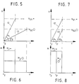
- FIGS. 5 to 8 The advantages of the measures and features according to the invention are clearly illustrated in FIGS. 5 to 8, in which the acceleration phases of the shears for two different rolling stock speeds and rolling stock cross sections are recorded.
- the symbol of a small dot ( . ) was chosen for small rolled sections and the symbol of a large circle (O) for large rolled sections.
- FIGS. 5 and 6 show the raising of the scissors, as is customary in the prior art.
- a steep acceleration path (12) with the angle ( ⁇ 1 ) and for the slow speed (v S2 . ) Results for the high speed (v S1 . )
- a small rolling stock cross section ( . ) O) with a larger cross section (O) a correspondingly flatter acceleration path (13) with the smaller angle ( ⁇ 2 ).
- FIGS. 7 and 8 have the same rolling stock cross sections and shear speeds of Figures 5 and 6 die corresponding acceleration paths and the resulting resulting moments recorded, which vary according to the arrangement a manual transmission between the scissors gear and Result drive motor.
Landscapes
- Engineering & Computer Science (AREA)
- Mechanical Engineering (AREA)
- Metal Rolling (AREA)
- Shearing Machines (AREA)
- Conveying And Assembling Of Building Elements In Situ (AREA)
- Manufacture Of Motors, Generators (AREA)
- Control Of Metal Rolling (AREA)
- Sawing (AREA)
Abstract
Description
Die Erfindung betrifft ein Verfahren und eine Vorrichtung zum
Betrieb von rotierenden Anlaufscheren
gemäß dem Oberbegriff des Patentanspruchs 1, bzw. 5 und wie z.B.
aus DE-A-3 020 084 bekannt.The invention relates to a method and an apparatus for
Operation of rotating start-up shears
according to the preamble of
Wichtig ist beim Betrieb derartiger Scheren, daß die Scherenmesser zumindest während des Schnittes eine solche Umfangsgeschwindigkeit haben, daß sie mit der Auslaufgeschwindigkeit des zu durchtrennenden Walzgutes übereinstimmt, weil sich sonst kein ordnungsgemäßer Trennschnitt durchführen läßt und sich Betriebsstörungen einstellen können.It is important when operating such scissors that the Scissors knife at least during the cut Have peripheral speed that they with the Run-out speed of the rolling stock to be cut matches, because otherwise no proper Separation cut can be carried out and malfunctions can adjust.
Bekannte Scheren, wie die in der DE 30 20 084 A1 und in der DE
30 42 171 A1 beschriebenen Trommelscheren mit zwei
Messertrommeln werden von einem Motor über eine
Getriebeanordnung gemeinsam angetrieben. Dies hat bei solchen
Scheren, die einen großen Geschwindigkeitsbereich abdecken
müssen, folgende Nachteile:
Ein weiterer Nachteil derartig ausgelegter Antriebe ist, daß der Schnitt erst nach Erreichen der jeweils erforderlichen maximalen Scherengeschwindigkeit erfolgt, was bedeutet, daß das maximale Motormoment bei Schnittbeginn nicht zur Verfügung steht. Dies bewirkt, daß der Motor zunächst in seiner Drehzahl einbricht und erst gegen Schnittende Solldrehzahl und maximales Motormoment wieder erreicht werden.Another disadvantage of such drives is that the cut only after reaching the required maximum scissor speed takes place, which means that the maximum engine torque is not available at the start of the cut stands. This causes the engine to start with its speed collapses and only towards the cutting end of the target speed and maximum engine torque can be reached again.
Aufgabe der Erfindung ist es, bekannte Anlaufscheren unter Vermeidung der geschilderten Nachteile so weiterzubilden, daß bei unterschiedlichen Walzgutgeschwindigkeiten und unterschiedlichen Walzgutquerschnitten ein optimaler Schnitt mit dem maximalen Motormoment möglich ist. The object of the invention is to include known starting scissors Avoidance of the disadvantages described so that at different rolling stock speeds and different rolling stock cross sections an optimal cut is possible with the maximum engine torque.
Die gestellte Aufgabe wird verfahrensmäßig gelöst mit den
Maßnahmen des Kennzeichnungsteils des Anspruchs 1 und
vorrichtungsmäßig mit den Merkmalen des Kennzeichnungsteiles
des Anspruchs 5. Vorteilhafte Ausgestaltungen der Erfindung
werden in den Unteransprüchen angegeben.The task is solved procedurally with the
Measures of the labeling part of
Durch die erfindungsgemäße Maßnahme, zwischen dem
Scherengetriebe und dem Antriebsmotor ein Schaltgetriebe
anzuordnen, verbunden jeweils über eine drehsteife Kupplung,
wird es möglich, im Arbeitsbereich mit hohen
Walzgutgeschwindigkeiten und kleinen Walzgutquerschnitten eine
kleine Übersetzung und bei langsamen Walzgutgeschwindigkeiten
und größeren Walzgutquerschnitten eine größere Übersetzung
auszuwählen. Durch diese erfindungsgemäße Maßnahme wird es
erstmals möglich, die Anlaufschere mit folgenden miteinander
verknüpften Arbeitsschritten zu regeln:
Die Regelung der Scherenmesser-Umfangsgeschwindigkeit während des Schnitts im Sinne einer optimalen Scherenvoreilung geschieht manuell durch den Betreiber, beispielsweise aufgrund akustischer und/oder visueller Signale, die durch das Geschwindigkeits-Überwachungsmeßgerät ausgelöst werden, oder aber die Regelung wird automatisch durch eine Regeleinheit vorgenommen, die zu diesem Zweck über Leitungen mit dem Überwachungsmeßgerät und dem Antriebsmotor verbunden ist.The regulation of the scissor knife peripheral speed during the cut in the sense of optimal scissors advance is done manually by the operator, for example due to acoustic and / or visual signals caused by the Speed monitoring device are triggered, or but the regulation is done automatically by a regulation unit made for this purpose via lines with the Monitoring measuring device and the drive motor is connected.
Durch die erfindungsgemäßen Merkmale und Maßnahmen, die in der Zwischenschaltung eines Schaltgetriebes zwischen dem Scherengetriebe und dem Antriebsmotor begründet sind, ist also eine Scherenregelung möglich, die optimal auf unterschiedliche Walzgutquerschnitte und Walzgutgeschwindigkeiten angepaßt werden kann.The features and measures according to the invention, which in the Interposition of a manual transmission between the Scissor gear and the drive motor are justified a scissor control possible, which optimally to different Rolling stock cross sections and rolling stock speeds adjusted can be.
In weiterer vorteilhafter Ausgestaltung der Erfindung kann zur Anpassung der Scherensollgeschwindigkeit an die maximale Beschleunigung der Schere der Startzeitpunkt der Schere so verschoben werden, daß mit einem veränderten Beschleunigungsweg die gewünschte konstante maximale Beschleunigung aufrecht erhalten bleiben kann.In a further advantageous embodiment of the invention Adjustment of the scissors set speed to the maximum Acceleration of the scissors the start time of the scissors like this be moved that with a changed Acceleration path the desired constant maximum Acceleration can be maintained.
Um das Erwärmen der Scherenmesser durch das Walzgut bei kurzen Beschleunigungswegen zu verhindern, warten erfindungsgemäß die Scherenmesser dabei bis kurz vor dem Schnitt und vor ihrer Beschleunigung in einer wärmegünstigen Warteposition.In order to heat the scissors knives through the rolling stock at short According to the invention, to prevent acceleration paths Scissor knife until just before the cut and before it Acceleration in a warm waiting position.
Weitere Einzelheiten, Merkmale und Vorteile der Erfindung ergeben sich aus den nachfolgenden Erläuterungen zu einem in schematischen Zeichnungsfiguren dargestellten Ausführungsbeispiel. Further details, features and advantages of the invention result from the following explanations for an in illustrated schematic drawing figures Embodiment.
Es zeigen:
- Fig. 1
- schematische Anordnung des Scherenantriebes entsprechend dem Stand der Technik,
- Fig. 2
- schematische Anordnung des Scherenantriebes mit Zwischenanordnung eines Schaltgetriebes,
- Fig. 3
- Geschwindigkeit-Zeitdiagramm für den gesamten Schnittvorgang,
- Fig. 4
- Moment-Zeitdiagramm für den gesamten Schnittvorgang,
- Fig. 5
- Geschwindigkeit-Zeitdiagramm nur für die Scherenbeschleunigungsphase (Stand der Technik),
- Fig. 6
- Moment-Zeitdiagramm nur für die Scherenbeschleunigungsphase (Stand der Technik),
- Fig. 7
- Geschwindigkeit-Zeitdiagramm nur für die Scherenbeschleunigungsphase mit Zwischenanordnung eines Schaltgetriebes,
- Fig. 8
- Moment-Zeitdiagramm nur für die Scherenbeschleunigungsphase mit Zwischenanordnung eines Schaltgetriebes.
- Fig. 1
- schematic arrangement of the scissors drive according to the prior art,
- Fig. 2
- schematic arrangement of the scissors drive with intermediate arrangement of a manual transmission,
- Fig. 3
- Speed-time diagram for the entire cutting process,
- Fig. 4
- Moment-time diagram for the entire cutting process,
- Fig. 5
- Speed-time diagram only for the scissors acceleration phase (prior art),
- Fig. 6
- Moment-time diagram only for the scissors acceleration phase (state of the art),
- Fig. 7
- Speed-time diagram only for the scissors acceleration phase with an intermediate arrangement of a manual transmission,
- Fig. 8
- Moment-time diagram only for the scissors acceleration phase with the intermediate arrangement of a manual transmission.
In der Figur 1 ist die schematische Anordnung des Antriebs einer Schere, wie sie in der DE 30 20 084 beschrieben ist, dargestellt. Der Antriebsmotor (9) ist hierbei über eine drehsteife Kupplung (10) direkt mit dem Scherengetriebe (7) gekoppelt.In Figure 1 is the schematic arrangement of the drive scissors as described in DE 30 20 084, shown. The drive motor (9) is a torsionally rigid coupling (10) directly with the scissors gear (7) coupled.
Entsprechend der Figur 2 ist erfindungsgemäß zwischen dem Scherengetriebe (7) und dem Antriebsmotor (9) ein Schaltgetriebe (8) angeordnet, daß mit dem Scherengetriebe (7) über eine drehsteife Kupplung (10) und mit dem Antriebsmotor (9) über eine drehsteife Kupplung (11) verbunden ist. Durch diese erfindungsgemäße Maßnahme kann die Regelung der Schere mit den Stufen
- Anfahren der Schere
- Hochfahren der Schere
- Schnitt des Walzgutes
- Starting the scissors
- Start up the scissors
- Cutting the rolled stock
Beginnend mit dem Start der Schere bei t1 wird die Schere langsam mit dem Moment (M1) angefahren bis zur Eliminierung des Getriebe- und Kupplungsspiels. Es folgt dann bei t2 der Start der Maximalbeschleunigung mit konstanter Steilheit mit dem Beschleunigungs-Moment (M2), unabhängig von der Walzgutgeschwindigkeit und von dem Walzgutquerschnitt bis zum Schnittbeginn bei t3. Die Scherengeschwindigkeit liegt bei diesem Schnittbeginn bereits oberhalb der Walzgutgeschwindigkeit (vM) aber noch unterhalb der Scherensollgeschwindigkeit (vS). Der beim Schnittbeginn einsetzende geringe Drehzahleinbruch bei t4 wird durch das Aufbringen des Maximalmoments (M3) minimiert und die Schere dabei weiter hochgefahren bis zur Scherensollgeschwindigkeit (vS) bei t5. Das ab hier bis zum Schnittende bei t6 noch aufzubringende Moment ist von geringem Betrag und ist in der Fig. 4 mit (M4) bezeichnet.Starting with the start of the scissors at t 1 , the scissors are slowly approached with the moment (M 1 ) until the gear and clutch play is eliminated. Then, at t 2, the maximum acceleration starts with constant steepness with the acceleration moment (M 2 ), regardless of the rolling stock speed and the rolling stock cross section until the start of cutting at t 3 . At this start of cut, the shear speed is already above the rolling stock speed (v M ) but still below the shear set speed (v S ). The slight drop in speed at t 4 that begins at the start of cutting is minimized by the application of the maximum torque (M 3 ) and the scissors continue to be raised up to the desired shear speed (v S ) at t 5 . The torque still to be applied from here to the end of the cut at t 6 is of a small amount and is designated by (M 4 ) in FIG. 4.
Die Vorteile der erfindungsgemäßen Maßnahmen und Merkmale werden anschaulich in den Figuren 5 bis 8 dargestellt, in denen die Beschleunigungsphasen der Schere für zwei unterschiedliche Walzgutgeschwindigkeiten und Walzgutquerschnitte aufgezeichnet sind. Für kleine Walzgutquerschnitte wurde dabei das Symbol eines kleinen Punktes (.) und für große Walzgutquerschnitte das Symbol eines großen Kreises (O) gewählt.The advantages of the measures and features according to the invention are clearly illustrated in FIGS. 5 to 8, in which the acceleration phases of the shears for two different rolling stock speeds and rolling stock cross sections are recorded. The symbol of a small dot ( . ) Was chosen for small rolled sections and the symbol of a large circle (O) for large rolled sections.
Hierbei zeigen die Figuren 5 und 6 das Hochfahren der Schere, wie es nach dem Stand der Technik üblich ist. Ausgehend von t2 dem Beginn der Beschleunigung, resultiert für die hohe Geschwindigkeit (vS1 .), verbunden mit einem kleinen Walzgutquerschnitt (.), ein steiler Beschleunigungsweg (12) mit dem Winkel (ε1) und für die langsame Geschwindigkeit (vS2O) mit einem größeren Querschnitt (O) ein entsprechend flacherer Beschleunigungsweg (13) mit dem kleineren Winkel (ε2). Bei gleichem Startpunkt t2 und gleich langen Beschleunigungswegen (12 = 13) ergibt sich hierbei für den kleinen Walzgutquerschnitt (.) ein maximales Beschleunigungs-Moment (M2 .), während das Beschleunigungs-Moment (M2O) für den großen Querschnitt (O) deutlich niedriger ist. FIGS. 5 and 6 show the raising of the scissors, as is customary in the prior art. Starting from t 2 the start of the acceleration, a steep acceleration path (12) with the angle (ε 1 ) and for the slow speed (v S2 . ) Results for the high speed (v S1 . ) Combined with a small rolling stock cross section ( . ) O) with a larger cross section (O) a correspondingly flatter acceleration path (13) with the smaller angle (ε 2 ). With the same starting point t 2 and the same length acceleration paths (12 = 13) results in this case for the small rolling stock (.), A maximum acceleration torque (M 2.) While the acceleration torque (M 2 O) for the large cross-section ( O) is significantly lower.
In den Figuren 7 und 8 sind bei gleichen Walzgutquerschnitten und Scherengeschwindigkeiten der Figuren 5 und 6 die entsprechenden Beschleunigungswege und die sich hieraus ergebenden Momente aufgezeichnet, die sich nach der Anordnung eines Schaltgetriebes zwischen dem Scherengetriebe und dem Antriebsmotor ergeben.FIGS. 7 and 8 have the same rolling stock cross sections and shear speeds of Figures 5 and 6 die corresponding acceleration paths and the resulting resulting moments recorded, which vary according to the arrangement a manual transmission between the scissors gear and Result drive motor.
Für die hohe Geschwindigkeit (vS1 .) und dem kleinen
Walzgutquerschnitt (.) ändert sich bei diesem
Ausführungsbeispiel gegenüber den Figuren 5 und 6 nichts. Für
die niedrige Geschwindigkeit (vS2O) mit dem großen
Walzgutquerschnitt (O) ergibt sich dagegen bei einem
verschobenen Startzeitpunkt t2, bei gleicher Steilheit (
Durch die Zwischenschaltung eines Schaltgetriebes in den Antriebsweg der Schere ist es also möglich, unabhängig von der benötigten Scherengeschwindigkeit und von dem Walzgutquerschnitt stets mit einem maximalen Beschleunigungsmoment die Schere hochzufahren, wodurch beim Schnittbeginn das volle Moment zur Verfügung steht und ein optimaler Schnitt ohne gravierenden Drehzahleinbruch gewährleistet wird.By interposing a manual transmission in the It is therefore possible to drive the scissors independently of the required scissors speed and from that Rolling stock cross section always with a maximum Acceleration moment to start up the scissors, which at Beginning of the cut the full moment is available and a optimal cut without serious drop in speed is guaranteed.
Claims (8)
- Method of operating rotating cropping shears in start-stop operation at roll stock of different speed in wire, refined steel, medium steel and billet roll trains, in which the cropping shears, the gear transmission (7) of which is connected with a drive motor (9) by way of a coupling (10), is accelerated from the rest setting to about rolling speed and is stopped again after a cut has been carried out, characterised in that a switching gear (8) is arranged between the shears gear transmission (7) and the drive motor (9), wherein the shears gear transmission (7) and switching gear (8) are connected together by way of a respective rotationally stiff coupling (10) and the switching gear (8) and drive motor (9) are connected together by way of a respective rotationally stiff coupling, with the assistance of which switching gear the combination of the following interlinked working steps is performed:a) starting up of the shears at low starting torque (M1) (about 10% of the nominal torque = 0.1 Mn) over the short interval which is required for elimination of gear and coupling play, on average over the interval of about 10 ms, thenb) constant acceleration of the shears with maximum steepness and maximum acceleration torque (M2) to the shears target speed (vS) for all roll stock speeds and cross-sections, wherein the shears target speed (vS) is selected to be greater than the speed of the roll stock (VM) (leading shears),c) beginning of the cutting shortly before attainment of the shears target speed (vS) at an instant t3 at which the shears speed is already greater than the speed of the roll stock (vM), andd) automatic monitoring of the circumferential speed of the knives of the shears during the cutting in order to maintain an optimum leading of the shears.
- Method according to claim 1, characterised in that the measurement signals of the monitoring of the circumferential speed of the knives of the shears are used for regulation of the circumferential speed of the knives of the shears.
- Method according to claim 1 or claim 2, characterised in that for matching of the maximum acceleration to the required shears target speed (vS) the start instant t1 of the shears is appropriately displaced and thus the acceleration path is correspondingly changed.
- Method according to claim 1, 2 or 3, characterised in that in the case of short acceleration paths the knives of the shears are disposed in a thermally favourable waiting position until shortly before the step.
- Device for carrying out the method according to one or more of the preceding claims, with a rotating cropping shears, the gear transmission (7) of which is coupled with a drive motor (9) by way of a coupling (10), characterised in that a switching gear (8) is arranged between the shears gear transmission (7) and the drive motor (9), wherein the shears gear transmission (7) and switching gear (8) are connected together by way of a respective rotationally stiff coupling (10) and the switching gear (8) and drive motor (9) are connected together by way of a respective rotationally stiff coupling (11).
- Device according to claim 5, characterised in that a measuring apparatus for automatic monitoring of the circumferential speed of the knives of the shears is arranged at the shears, the measurement signals of which flow into a regulating unit for control of the circumferential speed of the knives of the shears during the cutting.
- Device according to claim 5 or 6, characterised in that the switching gear (8) has more than two switching stages.
- Device according to claim 5 or 6, characterised in that the switching gear (8) is switchable steplessly.
Applications Claiming Priority (2)
| Application Number | Priority Date | Filing Date | Title |
|---|---|---|---|
| DE19633308 | 1996-08-19 | ||
| DE19633308A DE19633308A1 (en) | 1996-08-19 | 1996-08-19 | Method and device for operating rotating start-up shears |
Publications (2)
| Publication Number | Publication Date |
|---|---|
| EP0824984A1 EP0824984A1 (en) | 1998-02-25 |
| EP0824984B1 true EP0824984B1 (en) | 1999-12-22 |
Family
ID=7802969
Family Applications (1)
| Application Number | Title | Priority Date | Filing Date |
|---|---|---|---|
| EP97113088A Expired - Lifetime EP0824984B1 (en) | 1996-08-19 | 1997-07-30 | Process and device for driving rotating cropping shears |
Country Status (4)
| Country | Link |
|---|---|
| US (2) | US6164175A (en) |
| EP (1) | EP0824984B1 (en) |
| AT (1) | ATE187912T1 (en) |
| DE (2) | DE19633308A1 (en) |
Families Citing this family (3)
| Publication number | Priority date | Publication date | Assignee | Title |
|---|---|---|---|---|
| US7823492B2 (en) * | 2005-06-09 | 2010-11-02 | Siemens Industry, Inc. | Dual ratio drive for rotary shear |
| US8336433B2 (en) * | 2009-07-21 | 2012-12-25 | Siemens Industry, Inc. | Rotary shear |
| JP6960794B2 (en) * | 2017-07-29 | 2021-11-05 | 株式会社Rej | Rotary shear controller |
Family Cites Families (14)
| Publication number | Priority date | Publication date | Assignee | Title |
|---|---|---|---|---|
| DE1004451B (en) * | 1953-01-31 | 1957-03-14 | Hallden Machine Company | Flying scissors for dividing the material to be cut into sections of adjustable lengths with two cutting knives that come together independently of one another in the cutting position |
| DE2003922B2 (en) * | 1970-01-29 | 1971-08-26 | Ungerer Geb Dollinger | GEAR GEAR FOR DRIVING A FLYING SHEAR |
| DE2165627C2 (en) * | 1970-12-31 | 1984-06-14 | Kawasaki Jukogyo K.K., Kobe, Hyogo | Flying scissors for dividing sheet or plate-shaped goods |
| DE3020084A1 (en) * | 1980-05-27 | 1981-12-03 | Schloemann-Siemag AG, 4000 Düsseldorf | Cropping unit for rolled wire etc. moving at high speed - has cutting cylinders moved transversely for each cut to divert cropped wire end |
| DE3042171A1 (en) * | 1980-11-08 | 1982-06-16 | Hoestemberghe & Klütsch GmbH, 6630 Saarlouis | Shearing moving wire or steel bar - involves swivel tube guiding bar to blades fixed at cross-connections of annular grooves in rotating drums |
| JPS6179515A (en) * | 1984-09-25 | 1986-04-23 | Mitsubishi Heavy Ind Ltd | Fixed size cutting device of plate material |
| JPS6179516A (en) * | 1984-09-28 | 1986-04-23 | Ishikawajima Harima Heavy Ind Co Ltd | Flying shear |
| US4771667A (en) * | 1986-09-02 | 1988-09-20 | Metl-Saw System Inc | Precision metal cutting saw and assembly |
| US4926728A (en) * | 1986-09-05 | 1990-05-22 | Contour Saws, Inc. | Band saw for cutting shaped pieces of bar stock |
| US5260541A (en) * | 1990-12-10 | 1993-11-09 | Hitachi, Ltd. | Crop shear apparatus and crop shear equipment |
| ATE123983T1 (en) * | 1991-09-17 | 1995-07-15 | Gfm Fertigungstechnik | ROTARY OR STEERING LEVER SCISSORS. |
| EP0638375B1 (en) * | 1993-07-13 | 1996-11-13 | Siemens Aktiengesellschaft | Method and device for monitoring chattering in twin drives of tolling stands |
| AT405619B (en) * | 1995-04-25 | 1999-10-25 | Voest Alpine Ind Anlagen | ROLLING STAND |
| US5664472A (en) * | 1995-06-29 | 1997-09-09 | Mitsubishi Denki Kabushiki Kaisha | Cutter apparatus for coil conductor |
-
1996
- 1996-08-19 DE DE19633308A patent/DE19633308A1/en not_active Withdrawn
-
1997
- 1997-07-30 DE DE59700876T patent/DE59700876D1/en not_active Expired - Fee Related
- 1997-07-30 EP EP97113088A patent/EP0824984B1/en not_active Expired - Lifetime
- 1997-07-30 AT AT97113088T patent/ATE187912T1/en not_active IP Right Cessation
- 1997-08-18 US US08/914,873 patent/US6164175A/en not_active Expired - Fee Related
-
2000
- 2000-10-12 US US09/689,985 patent/US6349585B1/en not_active Expired - Fee Related
Also Published As
| Publication number | Publication date |
|---|---|
| US6164175A (en) | 2000-12-26 |
| EP0824984A1 (en) | 1998-02-25 |
| DE59700876D1 (en) | 2000-01-27 |
| DE19633308A1 (en) | 1998-02-26 |
| US6349585B1 (en) | 2002-02-26 |
| ATE187912T1 (en) | 2000-01-15 |
Similar Documents
| Publication | Publication Date | Title |
|---|---|---|
| DE102010014893A1 (en) | Device for processing ground surfaces | |
| DE3900734C2 (en) | Device for straightening and cutting round wire or the like | |
| DE102012102527A1 (en) | Press drive with two working areas | |
| EP1382238B1 (en) | Agricultural machine with continuously variable cone pulley transmission | |
| DE2823610A1 (en) | PENDULUM SHEARS | |
| EP0824984B1 (en) | Process and device for driving rotating cropping shears | |
| DE2461421A1 (en) | SAFETY GEAR SHIFTING ON A SNOW ROOM VEHICLE | |
| EP0420820B1 (en) | Process and device for drawing wire into a cutting device of a forming press | |
| DE2911765A1 (en) | COLD SHEARS, ESPECIALLY FOR CUTTING STICKS AND RODS | |
| EP1099501B1 (en) | High speed shearing machine for cutting rolled stock | |
| EP0532820B1 (en) | Rotational or lever shear | |
| DE6930577U (en) | CLUTCH MOTOR. | |
| DE102020103085A1 (en) | SLICING DEVICE WITH BLANK CUT FUNCTION | |
| DE102019102881B4 (en) | Method and control device for operating a drive train with a main and auxiliary drive and superimposed gear | |
| DE2818840C2 (en) | Feed device for grinding flat or spherical surfaces | |
| DE2718794A1 (en) | METHOD AND DEVICE FOR SHEARING HOT ROLLED STRIP | |
| EP1118409A1 (en) | Flying shear | |
| DE3630957A1 (en) | Rotating shears with speed control device allocated to their drive device | |
| DE597523C (en) | ||
| DE2130669A1 (en) | Open end spinning machine - has moving elements driven by single drive motor | |
| EP0784174A2 (en) | Armature with and electromotor actuator | |
| DE2922941A1 (en) | Pilger tube mill - with two feed carriages gearboxes and mandrel thrust blocks for higher throughput | |
| DE942243C (en) | Scissors that cut from a standing position for rolling stock | |
| DE2638120C3 (en) | Card | |
| AT165560B (en) | Machine for the production of wooden wire |
Legal Events
| Date | Code | Title | Description |
|---|---|---|---|
| PUAI | Public reference made under article 153(3) epc to a published international application that has entered the european phase |
Free format text: ORIGINAL CODE: 0009012 |
|
| 17P | Request for examination filed |
Effective date: 19970813 |
|
| AK | Designated contracting states |
Kind code of ref document: A1 Designated state(s): AT DE GB IT SE |
|
| AX | Request for extension of the european patent |
Free format text: AL;LT;LV;RO;SI |
|
| AKX | Designation fees paid |
Free format text: AT DE GB IT SE |
|
| RBV | Designated contracting states (corrected) |
Designated state(s): AT DE GB IT SE |
|
| GRAG | Despatch of communication of intention to grant |
Free format text: ORIGINAL CODE: EPIDOS AGRA |
|
| 17Q | First examination report despatched |
Effective date: 19990216 |
|
| GRAG | Despatch of communication of intention to grant |
Free format text: ORIGINAL CODE: EPIDOS AGRA |
|
| GRAG | Despatch of communication of intention to grant |
Free format text: ORIGINAL CODE: EPIDOS AGRA |
|
| GRAH | Despatch of communication of intention to grant a patent |
Free format text: ORIGINAL CODE: EPIDOS IGRA |
|
| GRAH | Despatch of communication of intention to grant a patent |
Free format text: ORIGINAL CODE: EPIDOS IGRA |
|
| GRAA | (expected) grant |
Free format text: ORIGINAL CODE: 0009210 |
|
| AK | Designated contracting states |
Kind code of ref document: B1 Designated state(s): AT DE GB IT SE |
|
| REF | Corresponds to: |
Ref document number: 187912 Country of ref document: AT Date of ref document: 20000115 Kind code of ref document: T |
|
| REF | Corresponds to: |
Ref document number: 59700876 Country of ref document: DE Date of ref document: 20000127 |
|
| ITF | It: translation for a ep patent filed | ||
| GBT | Gb: translation of ep patent filed (gb section 77(6)(a)/1977) |
Effective date: 20000302 |
|
| RAP2 | Party data changed (patent owner data changed or rights of a patent transferred) |
Owner name: SMS DEMAG AG |
|
| PLBE | No opposition filed within time limit |
Free format text: ORIGINAL CODE: 0009261 |
|
| STAA | Information on the status of an ep patent application or granted ep patent |
Free format text: STATUS: NO OPPOSITION FILED WITHIN TIME LIMIT |
|
| 26N | No opposition filed | ||
| PGFP | Annual fee paid to national office [announced via postgrant information from national office to epo] |
Ref country code: GB Payment date: 20010614 Year of fee payment: 5 |
|
| PGFP | Annual fee paid to national office [announced via postgrant information from national office to epo] |
Ref country code: SE Payment date: 20010702 Year of fee payment: 5 |
|
| PGFP | Annual fee paid to national office [announced via postgrant information from national office to epo] |
Ref country code: AT Payment date: 20010704 Year of fee payment: 5 |
|
| PGFP | Annual fee paid to national office [announced via postgrant information from national office to epo] |
Ref country code: DE Payment date: 20010713 Year of fee payment: 5 |
|
| REG | Reference to a national code |
Ref country code: GB Ref legal event code: IF02 |
|
| PG25 | Lapsed in a contracting state [announced via postgrant information from national office to epo] |
Ref country code: GB Free format text: LAPSE BECAUSE OF NON-PAYMENT OF DUE FEES Effective date: 20020730 Ref country code: AT Free format text: LAPSE BECAUSE OF NON-PAYMENT OF DUE FEES Effective date: 20020730 |
|
| PG25 | Lapsed in a contracting state [announced via postgrant information from national office to epo] |
Ref country code: SE Free format text: LAPSE BECAUSE OF NON-PAYMENT OF DUE FEES Effective date: 20020731 |
|
| PG25 | Lapsed in a contracting state [announced via postgrant information from national office to epo] |
Ref country code: DE Free format text: LAPSE BECAUSE OF NON-PAYMENT OF DUE FEES Effective date: 20030201 |
|
| EUG | Se: european patent has lapsed | ||
| GBPC | Gb: european patent ceased through non-payment of renewal fee |
Effective date: 20020730 |
|
| PG25 | Lapsed in a contracting state [announced via postgrant information from national office to epo] |
Ref country code: IT Free format text: LAPSE BECAUSE OF NON-PAYMENT OF DUE FEES;WARNING: LAPSES OF ITALIAN PATENTS WITH EFFECTIVE DATE BEFORE 2007 MAY HAVE OCCURRED AT ANY TIME BEFORE 2007. THE CORRECT EFFECTIVE DATE MAY BE DIFFERENT FROM THE ONE RECORDED. Effective date: 20050730 |