EP0824978A1 - Device for remodelling a hollow object - Google Patents
Device for remodelling a hollow object Download PDFInfo
- Publication number
- EP0824978A1 EP0824978A1 EP97202526A EP97202526A EP0824978A1 EP 0824978 A1 EP0824978 A1 EP 0824978A1 EP 97202526 A EP97202526 A EP 97202526A EP 97202526 A EP97202526 A EP 97202526A EP 0824978 A1 EP0824978 A1 EP 0824978A1
- Authority
- EP
- European Patent Office
- Prior art keywords
- mould
- mould cavity
- instance
- compression
- wall
- Prior art date
- Legal status (The legal status is an assumption and is not a legal conclusion. Google has not performed a legal analysis and makes no representation as to the accuracy of the status listed.)
- Ceased
Links
- 230000006835 compression Effects 0.000 claims abstract description 18
- 238000007906 compression Methods 0.000 claims abstract description 18
- 230000006837 decompression Effects 0.000 claims abstract description 9
- 238000007789 sealing Methods 0.000 claims abstract description 7
- 239000002184 metal Substances 0.000 claims abstract description 4
- 229910052751 metal Inorganic materials 0.000 claims abstract description 4
- 230000003247 decreasing effect Effects 0.000 claims abstract description 3
- 239000000203 mixture Substances 0.000 claims description 19
- 239000002360 explosive Substances 0.000 claims description 13
- 239000000567 combustion gas Substances 0.000 claims description 5
- 239000007789 gas Substances 0.000 claims description 3
- 230000002093 peripheral effect Effects 0.000 claims description 2
- 238000006073 displacement reaction Methods 0.000 description 9
- 238000004880 explosion Methods 0.000 description 8
- 238000011084 recovery Methods 0.000 description 4
- QVGXLLKOCUKJST-UHFFFAOYSA-N atomic oxygen Chemical compound [O] QVGXLLKOCUKJST-UHFFFAOYSA-N 0.000 description 2
- 238000004519 manufacturing process Methods 0.000 description 2
- VNWKTOKETHGBQD-UHFFFAOYSA-N methane Chemical compound C VNWKTOKETHGBQD-UHFFFAOYSA-N 0.000 description 2
- 239000001301 oxygen Substances 0.000 description 2
- 229910052760 oxygen Inorganic materials 0.000 description 2
- HSFWRNGVRCDJHI-UHFFFAOYSA-N alpha-acetylene Natural products C#C HSFWRNGVRCDJHI-UHFFFAOYSA-N 0.000 description 1
- 239000004411 aluminium Substances 0.000 description 1
- 229910052782 aluminium Inorganic materials 0.000 description 1
- XAGFODPZIPBFFR-UHFFFAOYSA-N aluminium Chemical compound [Al] XAGFODPZIPBFFR-UHFFFAOYSA-N 0.000 description 1
- 230000008901 benefit Effects 0.000 description 1
- 238000002485 combustion reaction Methods 0.000 description 1
- 230000008878 coupling Effects 0.000 description 1
- 238000010168 coupling process Methods 0.000 description 1
- 238000005859 coupling reaction Methods 0.000 description 1
- 230000005611 electricity Effects 0.000 description 1
- 125000002534 ethynyl group Chemical group [H]C#C* 0.000 description 1
- 230000007246 mechanism Effects 0.000 description 1
- 238000000034 method Methods 0.000 description 1
- 239000013641 positive control Substances 0.000 description 1
- 230000008569 process Effects 0.000 description 1
- 230000000717 retained effect Effects 0.000 description 1
- 239000005028 tinplate Substances 0.000 description 1
- 230000007704 transition Effects 0.000 description 1
Images



Classifications
-
- B—PERFORMING OPERATIONS; TRANSPORTING
- B29—WORKING OF PLASTICS; WORKING OF SUBSTANCES IN A PLASTIC STATE IN GENERAL
- B29C—SHAPING OR JOINING OF PLASTICS; SHAPING OF MATERIAL IN A PLASTIC STATE, NOT OTHERWISE PROVIDED FOR; AFTER-TREATMENT OF THE SHAPED PRODUCTS, e.g. REPAIRING
- B29C49/00—Blow-moulding, i.e. blowing a preform or parison to a desired shape within a mould; Apparatus therefor
- B29C49/42—Component parts, details or accessories; Auxiliary operations
- B29C49/78—Measuring, controlling or regulating
- B29C49/783—Measuring, controlling or regulating blowing pressure
-
- B—PERFORMING OPERATIONS; TRANSPORTING
- B21—MECHANICAL METAL-WORKING WITHOUT ESSENTIALLY REMOVING MATERIAL; PUNCHING METAL
- B21D—WORKING OR PROCESSING OF SHEET METAL OR METAL TUBES, RODS OR PROFILES WITHOUT ESSENTIALLY REMOVING MATERIAL; PUNCHING METAL
- B21D26/00—Shaping without cutting otherwise than using rigid devices or tools or yieldable or resilient pads, i.e. applying fluid pressure or magnetic forces
- B21D26/02—Shaping without cutting otherwise than using rigid devices or tools or yieldable or resilient pads, i.e. applying fluid pressure or magnetic forces by applying fluid pressure
- B21D26/06—Shaping without cutting otherwise than using rigid devices or tools or yieldable or resilient pads, i.e. applying fluid pressure or magnetic forces by applying fluid pressure by shock waves
- B21D26/08—Shaping without cutting otherwise than using rigid devices or tools or yieldable or resilient pads, i.e. applying fluid pressure or magnetic forces by applying fluid pressure by shock waves generated by explosives, e.g. chemical explosives
-
- B—PERFORMING OPERATIONS; TRANSPORTING
- B29—WORKING OF PLASTICS; WORKING OF SUBSTANCES IN A PLASTIC STATE IN GENERAL
- B29C—SHAPING OR JOINING OF PLASTICS; SHAPING OF MATERIAL IN A PLASTIC STATE, NOT OTHERWISE PROVIDED FOR; AFTER-TREATMENT OF THE SHAPED PRODUCTS, e.g. REPAIRING
- B29C49/00—Blow-moulding, i.e. blowing a preform or parison to a desired shape within a mould; Apparatus therefor
- B29C49/42—Component parts, details or accessories; Auxiliary operations
- B29C49/46—Component parts, details or accessories; Auxiliary operations characterised by using particular environment or blow fluids other than air
- B29C2049/4602—Blowing fluids
- B29C2049/4647—Blowing fluids created by an explosive gas mixture
-
- B—PERFORMING OPERATIONS; TRANSPORTING
- B29—WORKING OF PLASTICS; WORKING OF SUBSTANCES IN A PLASTIC STATE IN GENERAL
- B29C—SHAPING OR JOINING OF PLASTICS; SHAPING OF MATERIAL IN A PLASTIC STATE, NOT OTHERWISE PROVIDED FOR; AFTER-TREATMENT OF THE SHAPED PRODUCTS, e.g. REPAIRING
- B29C49/00—Blow-moulding, i.e. blowing a preform or parison to a desired shape within a mould; Apparatus therefor
- B29C49/42—Component parts, details or accessories; Auxiliary operations
- B29C49/4284—Means for recycling or reusing auxiliaries or materials, e.g. blowing fluids or energy
- B29C49/42845—Recycling or reusing of fluid, e.g. pressure
- B29C49/42855—Blowing fluids, e.g. reducing fluid consumption
-
- B—PERFORMING OPERATIONS; TRANSPORTING
- B29—WORKING OF PLASTICS; WORKING OF SUBSTANCES IN A PLASTIC STATE IN GENERAL
- B29C—SHAPING OR JOINING OF PLASTICS; SHAPING OF MATERIAL IN A PLASTIC STATE, NOT OTHERWISE PROVIDED FOR; AFTER-TREATMENT OF THE SHAPED PRODUCTS, e.g. REPAIRING
- B29C49/00—Blow-moulding, i.e. blowing a preform or parison to a desired shape within a mould; Apparatus therefor
- B29C49/42—Component parts, details or accessories; Auxiliary operations
- B29C49/4284—Means for recycling or reusing auxiliaries or materials, e.g. blowing fluids or energy
- B29C49/4287—Means for recycling or reusing auxiliaries or materials, e.g. blowing fluids or energy for use outside the blow-moulding apparatus, e.g. generating power or as pressurized plant air
-
- Y—GENERAL TAGGING OF NEW TECHNOLOGICAL DEVELOPMENTS; GENERAL TAGGING OF CROSS-SECTIONAL TECHNOLOGIES SPANNING OVER SEVERAL SECTIONS OF THE IPC; TECHNICAL SUBJECTS COVERED BY FORMER USPC CROSS-REFERENCE ART COLLECTIONS [XRACs] AND DIGESTS
- Y02—TECHNOLOGIES OR APPLICATIONS FOR MITIGATION OR ADAPTATION AGAINST CLIMATE CHANGE
- Y02P—CLIMATE CHANGE MITIGATION TECHNOLOGIES IN THE PRODUCTION OR PROCESSING OF GOODS
- Y02P70/00—Climate change mitigation technologies in the production process for final industrial or consumer products
- Y02P70/10—Greenhouse gas [GHG] capture, material saving, heat recovery or other energy efficient measures, e.g. motor control, characterised by manufacturing processes, e.g. for rolling metal or metal working
Definitions
- the invention relates to a device for expandingly remodelling a hollow object consisting of a body with a mouth opening and a bottom, for instance a metal can, a blown plastic, for instance PET, bottle or the like, which device comprises:
- Such a device is known from WO-A-95/08410.
- the known device makes use of supply of an explosive mixture into the object. By igniting thereof an internal pressure increase takes place which causes the object to expand and to assume a form which corresponds with that of the wall of the mould cavity. A pressure equalization with the ambient then takes place which is accompanied by a considerable noise production. The energy generated by the explosion is wholly lost in this manner.
- the stated objectives are generally realized with a device which has the feature that the decompression means are adapted to temporarily store at least a part of the energy coming available during the decompression and can co-act with the compression means such that at least a part of the stored energy is used for operation of the compression means.
- a particular embodiment is characterized by a feed for gas, for instance air, which feed is connected to a cylinder in which a piston movable by drive means is sealingly slidable.
- a very high compression ratio can be achieved with an embodiment in which a front part of the piston extends into the can in an extreme compression position.
- a very practical embodiment which is naturally suitable for storing energy has the feature that the drive means comprise flywheel means.
- Another embodiment has the special feature that the drive means comprise curve means.
- This embodiment comprises a curve track which co-acts with a curve follower which is guided positively by the curve track and is movable relative thereto.
- the curve follower is coupled to said piston to impart a reciprocating movement thereto.
- a preferred embodiment has a feed for gaseous explosive mixture into the object, ignition means for igniting this mixture and discharge means for combustion gases.
- This embodiment can have the very great advantage that after the device has been set into operation with external energy the successive explosions provide sufficient energy not only to remodel the objects but also to keep the whole process in motion. In this manner the explosions are as it were used in the manner of an internal combustion engine. In this manner the device will itself sustain its own operation.
- a very effective variant has the feature that the ignition means are adapted to operate in the region of the extreme compression position.
- the device can advantageously have the feature that at least two mould parts together bounding the peripheral wall of the mould cavity are movable at least more or less radially relative to the mould cavity and that locking means are present for locking relative to at least one other mould part during pressure build-up.
- the device is preferably characterized by at least one pressure equalization conduit debouching on the wall of the mould cavity.
- a specific embodiment has the special feature that the device is of the rotating type.
- Figure 1 shows a device 1 for expandingly remodelling metal cans.
- Figure 2 shows by way of example a mould cavity with three annular recesses 22, 23, 24.
- a can 2 is placed in the mould cavity while leaving clear space such that the can, which is manufactured for instance of tin plate or aluminium, can expand under internal pressure.
- the mould cavity is closed in the drawn manner for this purpose.
- a sealing ring 26 On the side of mouth opening 25 is arranged a sealing ring 26 such that the interior of can 2 is completely sealed.
- Via feed 27 for explosive mixture such a mixture, consisting for instance of acetylene or methane and oxygen or air, can be admitted into can 2.
- a sparking plug 28 is then energized. Due to the spark occurring there the explosive mixture explodes and owing to the pressure occurring in the can this can is plastically deformed into the state indicated schematically with dashed lines.
- the combustion gases are again discharged through the feed 27 now serving as discharge.
- a pressure equalization conduit 29 ensures that the air which has intruded between the outer wall of the can and the recesses 22,
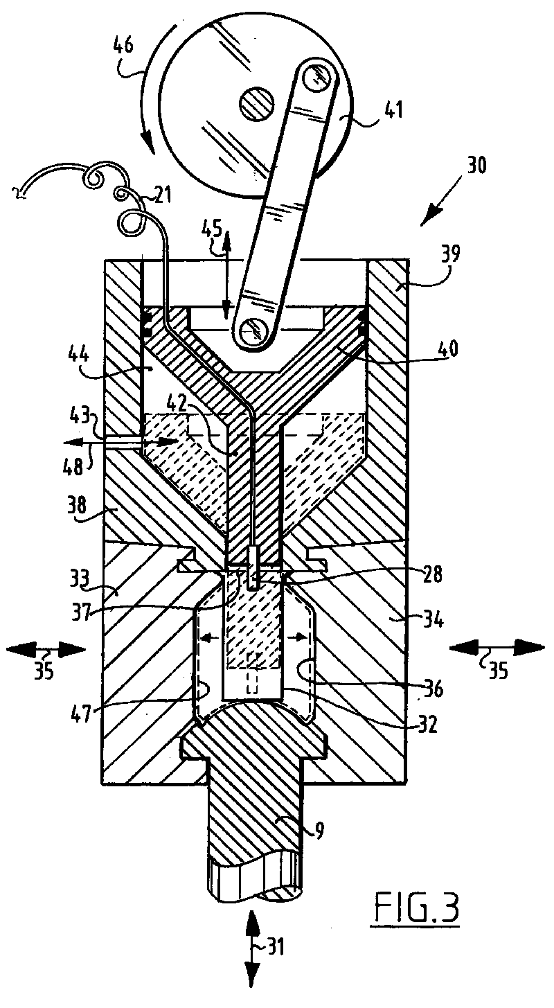
- Figure 3 shows a part of a device 30.
- Device 30 comprises the support table 9 which is movable up and downward as according to arrow 31. After a can 32 has been moved upward therewith the mould parts 33, 34 are moved toward each other as according to arrows 35 such that can 32 is wholly enclosed by the wall of mould cavity 36 and mouth opening 37 seals against mould part 38. It is noted that the co-action between said mould parts in the manner shown in figure 3 prevents a relative vertical displacement.
- Mould part 38 comprises a cylinder 39 in which a piston 40 is movable up and downward. The piston is connected to a schematically depicted flywheel device 41.
- Piston 40 has a cylindrical protruding bottom part 42 which in the lowest position during rotation of flywheel 41 can extend a considerable distance into can 32. This latter position is indicated with broken lines.
- an explosive mixture is admitted via feed 43 into cylinder space 44.
- cylinder 40 is moved downward as according to arrow 45 there takes place compression of this mixture and effective feed to and distribution in the space which is bounded by the inner surface of can 32 and the outer surface of the cylindrical bottom part 42.
- ignition of sparking plug 28 takes place whereby can 32 expands and acquires the form corresponding with the drawn wall of mould cavity 36.
- the remodelled can 47 is indicated with broken lines.
- the pressure increase occurring during the explosion not only results in the can 32 undergoing an expanding remodelling to the shape designated with 47 but also in piston 40 being subjected via part 42 to a substantial upward directed force which imparts extra rotation energy to flywheel 41 which meanwhile has passed its dead centre position.
- the feed 43 also serves for discharge of combustion gases. This is indicated symbolically with an arrow 48 pointing in two directions.
- the device can also operate without use of an explosive mixture and ignition thereof. In that case the device is not provided with the feed/discharge and with sparking plug 28 with connection 21. Flywheel 41 must then be driven by external motor means. It will be apparent that in that case the device cannot be self-sustaining, at least not as far as the energy recovery during the transition from compression to expansion is concerned.
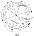
- Figure 4 shows the different processing stages.
- position 49 the cans are fed in.
- stage (a) positioning takes place through an angle of 36°.
- stage (b) upward displacement of a can takes place through an angle of 54°.
- stage (c) the mould is closed during an angular displacement of 54°.
- stage (d) compression takes place over 54°.
- stage (e) ignition and expansion take place through an angle of 18°.
- stage (f) a mould is opened over an angle of 54°.
- stage (g) the remodelled can is displaced downward through an angular displacement of 54° to be discharged at position 50.
- piston 54 of figures 5 and 6 is controlled for up and downward movement 45 not by a flywheel 41 but by a curve follower 51.
- This curve follower 51 co-acts for positive control with a curve track 52 which, as shown clearly in figure 6, is embodied as a groove in a cylinder rotatably driven for instance as according to arrow 53.
- figure 5 in particular is drawn somewhat schematically and not in the correct proportions.
- the feed of combustible mixture to the interior of can 32 via opening 53 takes place from the top.
- piston 54 In the highest position of piston 54 there is therefore a passage which ensures supply of the combustible mixture via opening 43 to the relevant space.
- This access can be embodied in the manner of figure 3 but alternatively it is also possible to opt for a passage through piston part 42, for instance in combination with a non-return valve.
- the described device can be wholly self-sustaining after a start-up period. It will be apparent that the speed at which the device operates must remain limited within certain values. In addition, the various successive stages must be mutually adjusted in time with a certain precision.
- the explosion of an explosive mixture must for instance only take place after a dead centre zone has been passed, whereby the explosion energy not used for deforming the can can enhance the continued displacement of a flywheel, carrousel, curve cylinder or the like. When there is surplus energy after an explosion this can be converted into for instance electrical energy.
- the flywheel which rotates at a more or less constant rotation speed, can for instance be coupled to an electric generator which can be controlled with known electronic means such that it makes the surplus energy easy to use, for instance feeds it back to the mains electricity supply. The electronic control in question can then be used effectively to control the speed with which the device operates.
Landscapes
- Engineering & Computer Science (AREA)
- Mechanical Engineering (AREA)
- Chemical & Material Sciences (AREA)
- Chemical Kinetics & Catalysis (AREA)
- General Chemical & Material Sciences (AREA)
- Physics & Mathematics (AREA)
- Fluid Mechanics (AREA)
- Manufacturing & Machinery (AREA)
- Portable Nailing Machines And Staplers (AREA)
- Moulds For Moulding Plastics Or The Like (AREA)
Abstract
Description
- 13
- upper seal
- 14
- safety screen
- 15
- three-way valve for feed of explosive mixture and discharge of combustion gases for each station individually
- 16
- cam and follower mechanisms for
valve units 15 - 17
- three-way valve system for collective feed of all stations with explosive mixture
- 18
- supply of combustible gas
- 19
- supply of air or oxygen
- 20
- rotating coupling and seal
- 21
- electrical connection for ignition system
- 22
- outer lifting device for cans 2. This is also operated by a curve follower.
Claims (10)
- Device for expandingly remodelling a hollow object consisting of a body with a mouth opening and a bottom, for instance a metal can, a blown plastic, for instance PET, bottle or the like, which device comprises:a mould comprising two mould parts, which mould parts are relatively movable between a closed position, in which they bound a mould cavity having a form which corresponds with the desired final form of an object, and an open position in which an object for remodelling can be placed and a remodelled object can be removed;sealing means for sealing the mouth opening against the wall of the closed mould cavity;compression means for increasing the pressure in the object placed in the closed mould cavity such that the object is thereby expanded against the wall of the mould cavity;decompression means for subsequently decreasing this pressure such that the mould parts can be moved to their open position in which a remodelled object can be removed;
characterized in thatthe decompression means are adapted to temporarily store at least a part of the energy coming available during the decompression and can co-act with the compression means such that at least a part of the stored energy is used for operation of the compression means. - Device characterized by a feed for gas, for instance air, which feed is connected to a cylinder in which a piston movable by drive means is sealingly slidable.
- Device as claimed in claim 2, characterized in that a front part of the piston extends into the can in an extreme compression position.
- Device as claimed in claim 2, characterized in that the drive means comprise flywheel means.
- Device as claimed in claim 2, characterized in that the drive means comprise curve means.
- Device as claimed in claim 1, characterized by a feed for gaseous explosive mixture into the object, ignition means for igniting this mixture and discharge means for combustion gases.
- Device as claimed in claims 2 and 6, characterized in that the ignition means are adapted to operate in the region of the extreme compression position.
- Device as claimed in claim 1, characterized in that at least two mould parts together bounding the peripheral wall of the mould cavity are movable at least more or less radially relative to the mould cavity and that locking means are present for locking relative to at least one other mould part during pressure build-up.
- Device as claimed in claim 1, characterized by at least one pressure equalization conduit debouching on the wall of the mould cavity.
- Device as claimed in claim 1, characterized in that the device is of the rotating type.
Applications Claiming Priority (2)
| Application Number | Priority Date | Filing Date | Title |
|---|---|---|---|
| NL1003827 | 1996-08-19 | ||
| NL1003827A NL1003827C2 (en) | 1996-08-19 | 1996-08-19 | Device for remodeling a hollow metal object. |
Publications (1)
| Publication Number | Publication Date |
|---|---|
| EP0824978A1 true EP0824978A1 (en) | 1998-02-25 |
Family
ID=19763384
Family Applications (1)
| Application Number | Title | Priority Date | Filing Date |
|---|---|---|---|
| EP97202526A Ceased EP0824978A1 (en) | 1996-08-19 | 1997-08-15 | Device for remodelling a hollow object |
Country Status (4)
| Country | Link |
|---|---|
| US (1) | US5895666A (en) |
| EP (1) | EP0824978A1 (en) |
| NL (1) | NL1003827C2 (en) |
| PL (1) | PL321672A1 (en) |
Cited By (7)
| Publication number | Priority date | Publication date | Assignee | Title |
|---|---|---|---|---|
| WO2002024435A1 (en) * | 2000-09-25 | 2002-03-28 | Sidel | Draw-blowing machine comprising improved drawing rod control |
| WO2003078136A3 (en) * | 2002-03-18 | 2003-12-11 | Tetra Laval Holdings & Finance | Device for the production of plastic containers by means of stretch blow moulding and device for coating the inner walls of a plastic container |
| WO2007017429A3 (en) * | 2005-08-05 | 2007-08-23 | Sipa Progettazione Automaz | Apparatus for recovering and converting energy |
| WO2010118728A1 (en) * | 2009-04-16 | 2010-10-21 | Khs Corpoplast Gmbh & Co. Kg | Method and device for blow-molding containers |
| DE102018117757A1 (en) * | 2018-07-23 | 2020-01-23 | Krones Ag | Device and method for forming plastic preforms into plastic containers by generating pressure by rotating a carrier |
| WO2020015871A1 (en) * | 2018-07-16 | 2020-01-23 | Krones Ag | Mould filling machine and mould filling method for a plastic container |
| DE102019102422A1 (en) * | 2019-01-31 | 2020-08-06 | E-PROPLAST-GmbH | Method and device for blowing pressure generation |
Families Citing this family (6)
| Publication number | Priority date | Publication date | Assignee | Title |
|---|---|---|---|---|
| CH691218A5 (en) * | 1996-08-14 | 2001-05-31 | Tetra Laval Holdings & Finance | Process for the sterilization of surfaces of any object. |
| US6182487B1 (en) * | 1998-02-18 | 2001-02-06 | Nippon Sanso Corporation | Metal vessel and a fabrication method for the same |
| DE19938724A1 (en) * | 1999-08-16 | 2001-02-22 | Tetra Laval Holdings & Finance | Device for the production of plastic containers by means of stretch blow molding |
| US20090140469A1 (en) * | 2007-01-08 | 2009-06-04 | Garrtech Inc. | One-piece blow mold halves for molding a container |
| DE102009044258A1 (en) * | 2009-10-15 | 2011-05-05 | Krones Ag | Plant and process for the production, filling, packaging and / or transport of beverages |
| CN101823302B (en) * | 2010-04-09 | 2012-06-20 | 江苏新美星包装机械有限公司 | Rotational blanking device of bottle blowing machine |
Citations (5)
| Publication number | Priority date | Publication date | Assignee | Title |
|---|---|---|---|---|
| GB2224965A (en) * | 1988-08-31 | 1990-05-23 | Metal Box Plc | Methods and apparatus for reshaping hollow members |
| JPH05309726A (en) * | 1990-12-18 | 1993-11-22 | Hirokazu Yoshioka | Fluid compression recycling apparatus |
| JPH0739958A (en) * | 1993-07-28 | 1995-02-10 | Nkk Corp | Detonation pressure processing device |
| WO1995008410A2 (en) * | 1993-09-21 | 1995-03-30 | Carnaudmetalbox Plc | Improvements in and relating to the shaping of articles |
| EP0655314A1 (en) * | 1993-11-26 | 1995-05-31 | KRUPP CORPOPLAST MASCHINENBAU GmbH | Multiple use of compressed air |
Family Cites Families (5)
| Publication number | Priority date | Publication date | Assignee | Title |
|---|---|---|---|---|
| US3252312A (en) * | 1962-04-25 | 1966-05-24 | Continental Can Co | Method and apparatus for explosive reshaping of hollow ductile objects |
| US3394569A (en) * | 1966-06-23 | 1968-07-30 | Gen Dynamics Corp | Forming method and apparatus |
| GB1436538A (en) * | 1972-11-17 | 1976-05-19 | Dale Ltd John | Manufacture of articles such as collapsible tubes |
| GB9114444D0 (en) * | 1991-07-04 | 1991-08-21 | Cmb Foodcan Plc | Apparatus and method for reshaping containers |
| US5419171A (en) * | 1993-10-14 | 1995-05-30 | The Boeing Company | Isostatic bulge forming |
-
1996
- 1996-08-19 NL NL1003827A patent/NL1003827C2/en not_active IP Right Cessation
-
1997
- 1997-08-15 EP EP97202526A patent/EP0824978A1/en not_active Ceased
- 1997-08-18 US US08/910,554 patent/US5895666A/en not_active Expired - Fee Related
- 1997-08-19 PL PL97321672A patent/PL321672A1/en unknown
Patent Citations (5)
| Publication number | Priority date | Publication date | Assignee | Title |
|---|---|---|---|---|
| GB2224965A (en) * | 1988-08-31 | 1990-05-23 | Metal Box Plc | Methods and apparatus for reshaping hollow members |
| JPH05309726A (en) * | 1990-12-18 | 1993-11-22 | Hirokazu Yoshioka | Fluid compression recycling apparatus |
| JPH0739958A (en) * | 1993-07-28 | 1995-02-10 | Nkk Corp | Detonation pressure processing device |
| WO1995008410A2 (en) * | 1993-09-21 | 1995-03-30 | Carnaudmetalbox Plc | Improvements in and relating to the shaping of articles |
| EP0655314A1 (en) * | 1993-11-26 | 1995-05-31 | KRUPP CORPOPLAST MASCHINENBAU GmbH | Multiple use of compressed air |
Non-Patent Citations (2)
| Title |
|---|
| PATENT ABSTRACTS OF JAPAN vol. 018, no. 115 (M - 1566) 24 February 1994 (1994-02-24) * |
| PATENT ABSTRACTS OF JAPAN vol. 095, no. 005 30 June 1995 (1995-06-30) * |
Cited By (16)
| Publication number | Priority date | Publication date | Assignee | Title |
|---|---|---|---|---|
| US7004745B2 (en) | 2000-09-25 | 2006-02-28 | Sidel | Stretch blow molding machine having improved control of the stretch rod |
| FR2814392A1 (en) * | 2000-09-25 | 2002-03-29 | Sidel Sa | STRETCH-BLOWING MACHINE HAVING IMPROVED DRAWING ROD CONTROL |
| WO2002024435A1 (en) * | 2000-09-25 | 2002-03-28 | Sidel | Draw-blowing machine comprising improved drawing rod control |
| US7481636B2 (en) | 2002-03-18 | 2009-01-27 | Tetra Laval Holdings & Finance S.A. | Device for the production of plastic containers by means of stretch blow moulding and device for coating the inner walls of a plastic container |
| JP2005520707A (en) * | 2002-03-18 | 2005-07-14 | テトラ ラバル ホールディングス アンド ファイナンス エス エイ | Plastic container manufacturing apparatus using stretch blow mold and plastic container inner surface coating apparatus |
| RU2312016C2 (en) * | 2002-03-18 | 2007-12-10 | Тетра Лаваль Холдингс Энд Файненс С.А. | Device for manufacture of the plastic containers by the blowing molding and the device for application of the coating on the internal walls of the plastic container |
| AU2003229561B2 (en) * | 2002-03-18 | 2008-03-06 | Tetra Laval Holdings & Finance S.A. | Device for the production of plastic containers by means of stretch blow moulding and device for coating the inner walls of a plastic container |
| WO2003078136A3 (en) * | 2002-03-18 | 2003-12-11 | Tetra Laval Holdings & Finance | Device for the production of plastic containers by means of stretch blow moulding and device for coating the inner walls of a plastic container |
| CN100528536C (en) * | 2002-03-18 | 2009-08-19 | 泰脱拉·拉伐尔持股金融股份有限公司 | Device for producing plastic containers by stretch blow moulding and device for coating the inner walls of plastic containers |
| WO2007017429A3 (en) * | 2005-08-05 | 2007-08-23 | Sipa Progettazione Automaz | Apparatus for recovering and converting energy |
| WO2010118728A1 (en) * | 2009-04-16 | 2010-10-21 | Khs Corpoplast Gmbh & Co. Kg | Method and device for blow-molding containers |
| CN102427928A (en) * | 2009-04-16 | 2012-04-25 | Khs科波普拉斯特有限责任公司 | Method and device for blow-molding containers |
| CN102427928B (en) * | 2009-04-16 | 2014-07-30 | Khs科波普拉斯特有限责任公司 | Method and device for blow-molding containers |
| WO2020015871A1 (en) * | 2018-07-16 | 2020-01-23 | Krones Ag | Mould filling machine and mould filling method for a plastic container |
| DE102018117757A1 (en) * | 2018-07-23 | 2020-01-23 | Krones Ag | Device and method for forming plastic preforms into plastic containers by generating pressure by rotating a carrier |
| DE102019102422A1 (en) * | 2019-01-31 | 2020-08-06 | E-PROPLAST-GmbH | Method and device for blowing pressure generation |
Also Published As
| Publication number | Publication date |
|---|---|
| US5895666A (en) | 1999-04-20 |
| PL321672A1 (en) | 1998-03-02 |
| NL1003827C2 (en) | 1998-02-26 |
Similar Documents
| Publication | Publication Date | Title |
|---|---|---|
| US5895666A (en) | Device for remodelling a hollow object | |
| CN1262396C (en) | Burning power tool | |
| US3224239A (en) | Pneumatic reshaping of cans | |
| CN1112641A (en) | Apparatus for mutual conversion between circular motion and reciprocal motion | |
| KR102353184B1 (en) | Rotary motor | |
| AU4161700A (en) | Combustion method for an internal combustion engine | |
| CN102713200A (en) | Crankless engine | |
| JP2018100667A (en) | Low energy high atmospheric pressure/hydraulic pressure/pneumatic pressure engine | |
| EP1474590A1 (en) | Rotating positive displacement engine | |
| US6279518B1 (en) | Rotary engine having a conical rotor | |
| US2997848A (en) | Rotary engine | |
| US3175360A (en) | Peripheral closed chamber engine | |
| JPH04101021A (en) | Rotary engine | |
| US1152386A (en) | Internal-combustion engine. | |
| CN101070779A (en) | All-rotation engine | |
| US2055137A (en) | Rotary engine | |
| JPH02196136A (en) | Internal combution engine | |
| US3948230A (en) | Rotary engine provided with first and secondary rotatably mounted rotors | |
| JPS5928735B2 (en) | Explosive expansion force rotating machine in which the passive body rotates in a perfect circle due to the explosive expansion force of the filling explosion chamber mixture. | |
| JP3075194U (en) | Improved structure of multi-unit single-stroke circular internal combustion engine | |
| RU2002116631A (en) | Device for storing and dropping a liferaft | |
| WO2005073553A2 (en) | A pollution-free engine | |
| JP2001152868A (en) | Structure of disc rotary type internal combustion engine in multi-unit single stroke | |
| CN106523142B (en) | A kind of internal combustion engine | |
| AU2019201844A1 (en) | Reciprocating Second Cylinder Internal Combustion Engine |
Legal Events
| Date | Code | Title | Description |
|---|---|---|---|
| PUAI | Public reference made under article 153(3) epc to a published international application that has entered the european phase |
Free format text: ORIGINAL CODE: 0009012 |
|
| AK | Designated contracting states |
Kind code of ref document: A1 Designated state(s): AT BE CH DE DK ES FI FR GB GR IE IT LI NL PT SE |
|
| 17P | Request for examination filed |
Effective date: 19980819 |
|
| AKX | Designation fees paid |
Free format text: AT BE CH DE DK ES FI FR GB GR IE IT LI NL PT SE |
|
| RBV | Designated contracting states (corrected) |
Designated state(s): AT BE CH DE DK ES FI FR GB GR IE IT LI NL PT SE |
|
| GRAG | Despatch of communication of intention to grant |
Free format text: ORIGINAL CODE: EPIDOS AGRA |
|
| 17Q | First examination report despatched |
Effective date: 20000627 |
|
| STAA | Information on the status of an ep patent application or granted ep patent |
Free format text: STATUS: THE APPLICATION HAS BEEN REFUSED |
|
| 18R | Application refused |
Effective date: 20001215 |