EP0824758B1 - Canon a electrons a grille - Google Patents
Canon a electrons a grille Download PDFInfo
- Publication number
- EP0824758B1 EP0824758B1 EP96914252A EP96914252A EP0824758B1 EP 0824758 B1 EP0824758 B1 EP 0824758B1 EP 96914252 A EP96914252 A EP 96914252A EP 96914252 A EP96914252 A EP 96914252A EP 0824758 B1 EP0824758 B1 EP 0824758B1
- Authority
- EP
- European Patent Office
- Prior art keywords
- grid
- electron gun
- cathode
- gun according
- sphere
- Prior art date
- Legal status (The legal status is an assumption and is not a legal conclusion. Google has not performed a legal analysis and makes no representation as to the accuracy of the status listed.)
- Expired - Lifetime
Links
Images


Classifications
-
- H—ELECTRICITY
- H01—ELECTRIC ELEMENTS
- H01J—ELECTRIC DISCHARGE TUBES OR DISCHARGE LAMPS
- H01J25/00—Transit-time tubes, e.g. klystrons, travelling-wave tubes, magnetrons
- H01J25/02—Tubes with electron stream modulated in velocity or density in a modulator zone and thereafter giving up energy in an inducing zone, the zones being associated with one or more resonators
- H01J25/04—Tubes having one or more resonators, without reflection of the electron stream, and in which the modulation produced in the modulator zone is mainly density modulation, e.g. Heaff tube
-
- H—ELECTRICITY
- H01—ELECTRIC ELEMENTS
- H01J—ELECTRIC DISCHARGE TUBES OR DISCHARGE LAMPS
- H01J1/00—Details of electrodes, of magnetic control means, of screens, or of the mounting or spacing thereof, common to two or more basic types of discharge tubes or lamps
- H01J1/02—Main electrodes
- H01J1/13—Solid thermionic cathodes
- H01J1/20—Cathodes heated indirectly by an electric current; Cathodes heated by electron or ion bombardment
-
- H—ELECTRICITY
- H01—ELECTRIC ELEMENTS
- H01J—ELECTRIC DISCHARGE TUBES OR DISCHARGE LAMPS
- H01J23/00—Details of transit-time tubes of the types covered by group H01J25/00
- H01J23/02—Electrodes; Magnetic control means; Screens
- H01J23/06—Electron or ion guns
- H01J23/07—Electron or ion guns producing a hollow cylindrical beam
-
- H—ELECTRICITY
- H01—ELECTRIC ELEMENTS
- H01J—ELECTRIC DISCHARGE TUBES OR DISCHARGE LAMPS
- H01J3/00—Details of electron-optical or ion-optical arrangements common to two or more basic types of discharge tubes or lamps
- H01J3/02—Electron guns
- H01J3/027—Construction of the gun or parts thereof
Definitions
- the field of the invention is that of electronic tubes and especially those with longitudinal electron beams with a grid such as IOT (abbreviation of the English terms Inductive Output Tube).
- An IOT has an electron gun that emits a beam of electrons, a resonant cavity which is crossed by the beam and a collector which collects the beam electrons as they exit the cavity.
- the electron gun has a cathode generally concave and shaped like a portion of a sphere, a control grid and a anode.
- the concave side of the cathode emits electrons when it is brought to high temperature. Electrons pass through the control grid and are attracted to the anode and then enter the resonant cavity in forming a longitudinal beam, see EP-A-0 578 525.
- the control grid is used to modulate the emission of electrons from so as to group them into packages before entering the cavity resonant.
- the cathode is generally made by a porous body impregnated with an emissive material.
- the porous body can be made of tungsten and the emissive material of barium, calcium and strontium aluminates. She begins to emit electrons around 900 ° to 1100 ° C.
- the control grid is very close to the cathode.
- the interval between the grid and the cathode is of the order of a few tenths of millimeters.
- Emissive material tends to evaporate and migrate especially on the control grid and on the anode.
- the grid heats up, partly because of the proximity of the cathode, and partly because of the electrons hitting it.
- the emissive material which migrated on the grid causes a parasitic emission of electrons which disturbs the functioning of the tube.
- the anode being relatively far from the cathode, it remains relatively cold and the emissive material covering it is not too embarrassing.
- Another way to avoid this emission of electrons parasite consists in reducing the temperature of the grid as much as possible during the operation of the tube.
- a known solution is to use a cathode working at lower temperatures than cathodes conventional to thereby lower the temperature of the control grid. This solution also does not give good results. The phenomenon spurious emission is only delayed but not eliminated.
- the present invention aims to remedy these drawbacks by offering an electron gun whose cathode contributes to better grid cooling and effectively prevents emission parasite.
- This cathode has an emissive part which delimits a substantially central recess which crosses it right through.
- the cathode is advantageously heated by a device heater which has a heating element opposite its part emissive, this heating element delimiting a recess facing the recess of the cathode.
- the grid has a solid part radiating thermally, intended to be placed facing the recess of the cathode. Dissipation thermal radiation grid is improved by this part full, radiating thermally, because it can radiate towards the recess of the cathode and towards the anode zone which is a cold zone. The grid being better cooled the stray electron emission is eliminated.
- the present invention also relates to an electronic tube comprising such a cannon.
- FIG. 1a shows in longitudinal section an electron gun known.
- the cathode has the reference 1. It is full and in the shape of portion of a sphere, its active face is concave.
- a heater 2 is in contact with the cathode 1 opposite its active face.
- Electrons emitted by the active face of cathode 1 pass through a control grid 3 and are attracted by an anode 4. They form a longitudinal axis beam XX '.
- Anode 4 has a central opening 5 to leave the beam of electrons entering a resonant cavity (not shown).
- Anode 4 is brought to a more positive potential than cathode 1.
- Grid 3 is generally brought to a potential intermediate between that of cathode 1 and that of anode 4.
- the grid 3 is mounted on a peripheral support 6 produced in a good thermal conductive material such as copper. She is also in shape of a portion of a sphere with first bars 7 arranged on parallels of the sphere and of the second bars 8 arranged on meridians of the sphere. The two portions of sphere i.e. that of the cathode 1 and that of grid 3 have their center on the axis XX '.
- Figure 1b shows the front view of the grid.
- cathode 1 heats emissive material evaporates and it will notably cover the grid 3. By heating the grid starts to emit parasitic electrons.
- the grid 3 is cooled in one leaves by conduction to the peripheral support 6 via the first and second bars 7, 8, and on the other hand by radiation towards the anode 4 essentially.
- the hottest part of the grid 3 is its central part. Any increasing the size of cathode 1 leads to increasing the size of the grid 3 and therefore the temperature of its central part. To avoid increasing the parasitic emission from the grid 3, we are forced to limit the size of the cathode 1 and therefore the electronic current which it supplies.
- FIGS 2a and 2b show from the front and in longitudinal section an example of a cathode 10 of a cannon according to the invention.
- the cathode is a portion of a sphere. It has a part emissive 12 which defines a substantially central recess 11.
- the emissive part 12 is concave and substantially shaped like a segment of a sphere and the recess 11 is substantially circular.
- the emissive surface of a cathode such as that of Figure 1a varies at first order as the square of its diameter.
- the diameter of the recess 11 represents approximately 30 to 40% of the diameter of the cathode 10
- the surface of the recess 11 is relatively small and has no practically no influence on the electronic emission.
- the low loss of emissive surface can be offset by a small increase in cathode diameter 10.
- a conventional solid cathode in 38 mm diameter spherical cap shape has the same surface that a cathode according to the invention whose emissive part is in segment spherical 40 millimeters in diameter and whose recess has a diameter 15 millimeters.
- FIG. 3 represents the drawing of a grid of a cannon according to the invention.
- This grid is intended to be associated with a cathode of the type from that shown in Figures 2a and 2b.
- the grid has a part 24 full, thermally radiating, intended to be placed facing the cathode recess.
- the grid When the grid is mounted in a barrel electrons with such an electron-emitting cathode, it can radiate on the one hand towards the anode and on the other hand towards the recess of the cathode.
- This grid is effectively cooled and stray electron emission is eliminated.
- the diameter of the cathode is dissociated from the grid temperature and we can consider design more powerful electronic tubes with this type of gun.
- the part 24 full of the grid 23 is made of a material having a capacity of thermal radiation close to that of the black body.
- Graphite and more particularly pyrolitic graphite is a particularly good material suitable for making this solid part 24 radiating thermally.
- the grid shown in Figure 3 has around the part 24 full an openwork part 26 which is intended to be crossed by the electrons emitted from the cathode.
- the openwork part 26 may also be made of pyrolitic graphite because of its thermal properties, advantageous electrical and mechanical.
- the grid 23 is intended to be used with a cathode substantially in the shape of a portion of a sphere, it is preferable that it be also substantially in the form of a portion of a sphere.
- the full part 24 can be in the form of a spherical cap and the perforated part 26 may include first bars 28 arranged along meridians of the sphere and second bars 29 along parallels of the sphere.
- the grid 23 can be produced from a graphite blank pyrolitic, for example in the form of a portion of a sphere, in which sizes the bars 28, 29 and the solid part 24. This size can be achieved conventionally, for example by laser machining or by sandblasting.
- the openwork part 26 of the grid has substantially rectangular or hexagonal openings.
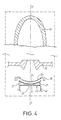
- FIG. 4 shows in longitudinal section, an example of a cannon with electrons according to the invention mounted in an electronic tube also according to the invention.
- the barrel comprises a cathode 21 according to the invention and a control grid 23 both substantially in the form of portion of sphere.
- the cathode 21 has an emissive part 27 in the form of a segment of a sphere which delimits a recess 22 substantially central.
- An anode 25 and a heater 40 of the cathode have also been shown in this figure.
- the electronic tube is partially shown. It features the electron gun and the electrons emitted are finally recovered from the race in a collector 43.
- the grid 23 associated with the cathode according to the invention comprises a solid part 24. It is comparable to that of the figure 3. Its heat dissipation is better than in the barrel of the Figure 1a.
- the bars 28, 29 of the grid are cooled by conduction, both to the support peripheral 30 and towards the solid part 24 radiating thermally.
- the solid part 24 is cooled by radiation towards the anode 25 and towards the recess 22 of the cathode 21.
- the length of the first bars 28 is considerably reduced compared to that of the bars of Figure 1b. For example, their length can go from around 41 millimeters to around 14.5 millimeters in the example cited above.
- the solid part 24 of the grid 23 will have substantially the same size as the recess 22 of the cathode 21.
- the cathode according to the invention is associated with a grid without a solid part, i.e. a traditional grid like the one in Figure 1b, for example. If this grid is carried out in a material having a radiation capacity close to that of the black body, the part of the grid facing the cathode recess can radiate towards this obviously.
- the cooling of the central part of the grid is improved compared to that of a grid as shown in Figure 1a and associated with a full cathode but it is not as good as in the case of the figure 4. However in some cases, this cooling is completely sufficient.
- a device 40 for indirect heating of the cathode has been shown in the figure 4. It is seen from the front in figure 5. It is intended to heat the part emissive 27 of the cathode 21. It is disposed near the convex face of cathode 21. It includes a heating element 42 defining a recess 41 facing the recess 22 of the cathode 21. It may be shaped of perforated plate defining a network of conductors 45 in which can circulate an electric current. This tray will be produced, preferably in an electrically conductive material, having a radiation capacity thermal close to that of the black body. Pyrolitic graphite is particularly suitable for producing the heating element 42. In the example in Figure 5, the plate has a series of slots 44 in an arc concentric, the slots 44 placed on two successive circles being offset from each other. The space between the slots 44 forms the network of electrical conductors 42.
- the barrel according to the invention is not limited to a cathode in portion of sphere, nor to a grid in portion of sphere.
Landscapes
- Microwave Tubes (AREA)
- Electron Sources, Ion Sources (AREA)
Description
- les figures 1a,1b respectivement une coupe longitudinale d'un canon à électrons de l'art antérieur et une vue de face de sa grille;
- les figures 2a, 2b respectivement une vue de face et une coupe transversale d'un exemple d'une cathode d'un canon conforme à l'invention;
- la figure 3 une vue de face d'un exemple d'une grille d'un canon conforme à l'invention;
- la figure 4 une coupe schématique longitudinale d'un exemple d'un canon à électrons conforme à l'invention monté dans un tube électronique également conforme à l'invention;
- la figure 5 une vue de face d'un dispositif pour chauffer la cathode du canon selon l'invention.
Claims (16)
- Canon à électrons à grille comportant une cathode avec une partie émissive (27), caractérisé en ce que la partie émissive (27) délimite un évidement (22) qui la traverse de part en part et qui est sensiblement central de manière à contribuer au refroidissement de la grille.
- Canon à électrons selon la revendication 1, caractérisé en ce que la partie émissive (27) de la cathode est sensiblement un segment de sphère.
- Canon à électrons selon l'une des revendications 1 ou 2, caractérisé en ce que l'évidement (22) de la cathode est sensiblement circulaire.
- Canon à électrons selon l'une des revendications 2 ou 3, caractérisé en ce que le diamètre de l'évidement (22) de la cathode représente environ 30 à 40% du diamètre de la partie émissive (27).
- Canon à électrons selon l'une des revendications 1 à 4, caractérisé en ce qu'il comporte un dispositif de chauffage (40) de la cathode avec un élément chauffant (42) délimitant un évidement (41) disposé face à l'évidement (22) de la cathode.
- Canon à électrons selon la revendication 5, caractérisé en ce que l'élément chauffant (42) est un plateau ajouré définissant un réseau de conducteurs (45) électriques.
- Canon à électrons selon l'une des revendications 5 ou 6, caractérisé en ce que l'élément chauffant (42) est réalisé en graphite pyrolitique.
- Canon à électrons selon l'une des revendications 1 à 7, caractérisé en ce que la grille possède une partie (24) pleine, rayonnant thermiquement, destinée à être disposée face à l'évidement (22) de la cathode (21).
- Canon à électrons selon la revendication 8, caractérisé en ce que la partie (24) pleine de la grille, rayonnant thermiquement, a sensiblement les mêmes dimensions que l'évidement (22) de la cathode (21).
- Canon à électrons selon l'une des revendications 8 ou 9, caractérisé en ce que la partie (24) pleine de la grille, rayonnant thermiquement, est réalisée dans un matériau ayant une capacité de rayonnement thermique proche de celle du corps noir.
- Canon à électrons selon la revendication 10, caractérisé en ce que la partie (24) pleine de la grille, rayonnant thermiquement, est réalisée en graphite pyrolitique.
- Canon à électrons selon l'une des revendications 8 à 11, caractérisé en ce que la grille comporte une partie ajourée (26) autour de la partie (24) pleine, cette partie ajourée (26) étant destinée à être traversée par les électrons émis par la cathode (21).
- Canon à électrons selon la revendication 12, caractérisé en ce que la grille sensiblement en forme de portion de sphère comporte une partie ajourée avec des premiers barreaux (28) disposés selon des méridiens de la sphère et des seconds barreaux (29) selon des parallèles de la sphère.
- Canon à électrons selon l'une des revendications 8 à 13, caractérisé en ce que la partie (24) pleine de la grille, rayonnant thermiquement, est sensiblement en calotte sphérique.
- Canon à électrons selon l'une des revendications 1 à 14, caractérisé en ce que la grille est entourée d'un support périphérique (30) réalisé dans un matériau bon conducteur thermique.
- Tube électronique caractérisé en ce qu'il comporte un canon à électrons à grille selon l'une des revendications 1 à 15.
Applications Claiming Priority (3)
| Application Number | Priority Date | Filing Date | Title |
|---|---|---|---|
| FR9505408A FR2733856B1 (fr) | 1995-05-05 | 1995-05-05 | Cathode pour canon a electrons a grille, grille destinee a etre associee avec une telle cathode et canon a electrons comportant une telle cathode |
| FR9505408 | 1995-05-05 | ||
| PCT/FR1996/000644 WO1996035219A1 (fr) | 1995-05-05 | 1996-04-26 | Canon a electrons a grille |
Publications (2)
| Publication Number | Publication Date |
|---|---|
| EP0824758A1 EP0824758A1 (fr) | 1998-02-25 |
| EP0824758B1 true EP0824758B1 (fr) | 2001-08-16 |
Family
ID=9478747
Family Applications (1)
| Application Number | Title | Priority Date | Filing Date |
|---|---|---|---|
| EP96914252A Expired - Lifetime EP0824758B1 (fr) | 1995-05-05 | 1996-04-26 | Canon a electrons a grille |
Country Status (7)
| Country | Link |
|---|---|
| US (1) | US5936335A (fr) |
| EP (1) | EP0824758B1 (fr) |
| JP (1) | JP4019431B2 (fr) |
| CN (1) | CN1099689C (fr) |
| DE (1) | DE69614520T2 (fr) |
| FR (1) | FR2733856B1 (fr) |
| WO (1) | WO1996035219A1 (fr) |
Families Citing this family (12)
| Publication number | Priority date | Publication date | Assignee | Title |
|---|---|---|---|---|
| GB9712243D0 (en) * | 1997-06-13 | 1997-08-13 | Eev Ltd | Grids |
| FR2775118B1 (fr) | 1998-02-13 | 2000-05-05 | Thomson Tubes Electroniques | Grille pour tube electronique a faisceau axial a performances ameliorees |
| FR2789800B1 (fr) | 1999-02-16 | 2001-05-11 | Thomson Tubes Electroniques | Generateur radiofrequence de tres grande puissance |
| GB9915925D0 (en) * | 1999-07-08 | 1999-09-08 | Univ Loughborough | Flow field plates |
| US7345290B2 (en) * | 1999-10-07 | 2008-03-18 | Agere Systems Inc | Lens array for electron beam lithography tool |
| US6528799B1 (en) * | 2000-10-20 | 2003-03-04 | Lucent Technologies, Inc. | Device and method for suppressing space charge induced aberrations in charged-particle projection lithography systems |
| FR2853450B1 (fr) * | 2003-04-04 | 2006-09-08 | Thales Sa | Grille de commande d'un tube electronique |
| JP4113032B2 (ja) * | 2003-04-21 | 2008-07-02 | キヤノン株式会社 | 電子銃及び電子ビーム露光装置 |
| JP5148582B2 (ja) | 2009-10-20 | 2013-02-20 | 株式会社エー・アンド・デイ | 圧力を利用したリークテスター |
| CN105414732B (zh) * | 2015-12-23 | 2018-06-29 | 哈尔滨工业大学(威海) | 多阴极电子枪装置 |
| CN106216788B (zh) * | 2016-08-23 | 2019-07-02 | 安徽华东光电技术研究所 | 一种电子控制栅网焊接工装的焊接方法 |
| CN115699241B (zh) * | 2020-06-15 | 2025-03-28 | 上海联影医疗科技股份有限公司 | 电子枪 |
Family Cites Families (15)
| Publication number | Priority date | Publication date | Assignee | Title |
|---|---|---|---|---|
| FR960750A (fr) * | 1950-04-22 | |||
| US2936393A (en) * | 1956-12-28 | 1960-05-10 | Hughes Aircraft Co | Low noise traveling-wave tube |
| US2985789A (en) * | 1960-02-17 | 1961-05-23 | Bell Telephone Labor Inc | Low-noise electron gun |
| DE1212227B (de) * | 1961-12-13 | 1966-03-10 | Deutsche Bundespost | Flaechenkathode fuer Elektronenstrahlroehren |
| FR1523248A (fr) * | 1967-03-07 | 1968-05-03 | Thomson Houston Comp Francaise | Perfectionnements aux procédés de fabrication d'électrodes en forme de grilles pour tubes électroniques, électrodes fabriquées à l'aide de ces procédés perfectionnés et tubes électroniques contenant de telles électrodes |
| DE2214660A1 (de) * | 1971-04-12 | 1973-12-06 | Werk Fernsehelektronik Veb | Katode fuer laufzeitroehren |
| FR2445605A1 (fr) * | 1978-12-27 | 1980-07-25 | Thomson Csf | Cathode a chauffage direct et tube electronique haute frequence comportant une telle cathode |
| FR2498372A1 (fr) * | 1981-01-16 | 1982-07-23 | Thomson Csf | Cathode a chauffage direct, son procede de fabrication, et tube electronique incorporant une telle cathode |
| FR2532468A1 (fr) * | 1982-08-31 | 1984-03-02 | Thomson Csf | Perfectionnement aux cathodes a chauffage direct |
| US4583021A (en) * | 1983-04-18 | 1986-04-15 | Litton Systems, Inc. | Electron gun with improved cathode and shadow grid configuration |
| US4553064A (en) * | 1983-08-30 | 1985-11-12 | Hughes Aircraft Company | Dual-mode electron gun with improved shadow grid arrangement |
| US4737680A (en) * | 1986-04-10 | 1988-04-12 | Litton Systems, Inc. | Gridded electron gun |
| US4745326A (en) * | 1986-12-10 | 1988-05-17 | The United States Of America As Represented By The Secretary Of The Navy | Method of manufacturing integral shadow gridded controlled porosity, dispenser cathodes |
| FR2693028A1 (fr) * | 1992-06-26 | 1993-12-31 | Thomson Tubes Electroniques | Canon à électrons à échauffement réduit de la grille. |
| FR2728386B1 (fr) * | 1994-12-20 | 1997-01-24 | Thomson Tubes Electroniques | Tube electronique a grille a performances ameliorees |
-
1995
- 1995-05-05 FR FR9505408A patent/FR2733856B1/fr not_active Expired - Fee Related
-
1996
- 1996-04-26 CN CN96193728A patent/CN1099689C/zh not_active Expired - Fee Related
- 1996-04-26 WO PCT/FR1996/000644 patent/WO1996035219A1/fr not_active Ceased
- 1996-04-26 DE DE69614520T patent/DE69614520T2/de not_active Expired - Lifetime
- 1996-04-26 JP JP53306796A patent/JP4019431B2/ja not_active Expired - Fee Related
- 1996-04-26 US US08/945,675 patent/US5936335A/en not_active Expired - Lifetime
- 1996-04-26 EP EP96914252A patent/EP0824758B1/fr not_active Expired - Lifetime
Also Published As
| Publication number | Publication date |
|---|---|
| US5936335A (en) | 1999-08-10 |
| EP0824758A1 (fr) | 1998-02-25 |
| FR2733856A1 (fr) | 1996-11-08 |
| CN1099689C (zh) | 2003-01-22 |
| DE69614520D1 (de) | 2001-09-20 |
| DE69614520T2 (de) | 2002-05-08 |
| FR2733856B1 (fr) | 1997-08-29 |
| JP4019431B2 (ja) | 2007-12-12 |
| JPH11505059A (ja) | 1999-05-11 |
| CN1183852A (zh) | 1998-06-03 |
| WO1996035219A1 (fr) | 1996-11-07 |
Similar Documents
| Publication | Publication Date | Title |
|---|---|---|
| EP0824758A1 (fr) | Canon a electrons a grille | |
| FR2744564A1 (fr) | Corps de cathode, canon a electrons, et tube a rayons cathodiques, utilisant un emetteur ferroelectrique | |
| EP0110734B1 (fr) | Tube à rayons X produisant un faisceau à haut rendement, notamment en forme de pinceau | |
| FR2527005A1 (fr) | Tube electronique de puissance a grille perfectionne | |
| EP0589030B1 (fr) | Canon a electrons compact comportant une source d'electrons a micropointes et laser a semi-conducteur utilisant ce canon pour le pompage electronique | |
| FR2675629A1 (fr) | Cathode pour tube a rayons x et tube ainsi obtenu. | |
| EP0003937B1 (fr) | Cathode pour canon électronique | |
| EP0587481B1 (fr) | Tube électronique à structure radiale | |
| EP1052680B1 (fr) | Générateur impulsionnel d'électrons | |
| EP0319402B1 (fr) | Utilisation d'un canon à électrons pour tube à rayonnement cathodique | |
| EP0126668A1 (fr) | Tube radiogène à anode tournante | |
| EP1292963A1 (fr) | Cathode a rendement thermique optimise | |
| EP0578525A1 (fr) | Canon à électrons à échauffement réduit de la grille | |
| EP0349388A1 (fr) | Tube radiogène à auto-limitation du flux électronique par saturation | |
| EP1055246B1 (fr) | Grille pour tube electronique a faisceau axial | |
| FR2635913A1 (fr) | Diode a emission de champ | |
| FR2461352A1 (fr) | Dispositif muni d'un tube de camera de television et tube de camera de television destine a un tel dispositif | |
| FR2555809A1 (fr) | Tube a rayons cathodiques ayant un systeme de canons electroniques muni de moyens modifiant le pouvoir emissif | |
| FR2564638A1 (fr) | Tube a rayons cathodiques a canon en ligne | |
| FR2752643A1 (fr) | Cathode froide a emission de champ electrique | |
| FR2925758A1 (fr) | Tube electronique a cavite resonnante | |
| FR2647257A1 (fr) | Cathode impregnee avec capacite reduite avec application aux tubes de visualisation du type indexation de faisceau, et tubes electroniques comprenant un tel dispositif | |
| EP0020218A1 (fr) | Collecteur déprimé à plusieurs étages, refroidi par rayonnement, pour tube hyperfréquence, et tube hyperfréquence comportant un tel collecteur | |
| FR2767963A1 (fr) | Four a micro-ondes equipe d'un dispositif de production de micro-ondes structurellement simple | |
| BE416793A (fr) |
Legal Events
| Date | Code | Title | Description |
|---|---|---|---|
| PUAI | Public reference made under article 153(3) epc to a published international application that has entered the european phase |
Free format text: ORIGINAL CODE: 0009012 |
|
| 17P | Request for examination filed |
Effective date: 19971025 |
|
| AK | Designated contracting states |
Kind code of ref document: A1 Designated state(s): DE FR GB |
|
| GRAG | Despatch of communication of intention to grant |
Free format text: ORIGINAL CODE: EPIDOS AGRA |
|
| 17Q | First examination report despatched |
Effective date: 20001208 |
|
| GRAG | Despatch of communication of intention to grant |
Free format text: ORIGINAL CODE: EPIDOS AGRA |
|
| GRAH | Despatch of communication of intention to grant a patent |
Free format text: ORIGINAL CODE: EPIDOS IGRA |
|
| GRAH | Despatch of communication of intention to grant a patent |
Free format text: ORIGINAL CODE: EPIDOS IGRA |
|
| GRAA | (expected) grant |
Free format text: ORIGINAL CODE: 0009210 |
|
| RAP1 | Party data changed (applicant data changed or rights of an application transferred) |
Owner name: THALES ELECTRON DEVICES S.A. |
|
| AK | Designated contracting states |
Kind code of ref document: B1 Designated state(s): DE FR GB |
|
| REF | Corresponds to: |
Ref document number: 69614520 Country of ref document: DE Date of ref document: 20010920 |
|
| GBT | Gb: translation of ep patent filed (gb section 77(6)(a)/1977) |
Effective date: 20011116 |
|
| REG | Reference to a national code |
Ref country code: GB Ref legal event code: IF02 |
|
| PLBE | No opposition filed within time limit |
Free format text: ORIGINAL CODE: 0009261 |
|
| STAA | Information on the status of an ep patent application or granted ep patent |
Free format text: STATUS: NO OPPOSITION FILED WITHIN TIME LIMIT |
|
| 26N | No opposition filed | ||
| PGFP | Annual fee paid to national office [announced via postgrant information from national office to epo] |
Ref country code: DE Payment date: 20120502 Year of fee payment: 17 |
|
| PGFP | Annual fee paid to national office [announced via postgrant information from national office to epo] |
Ref country code: GB Payment date: 20120425 Year of fee payment: 17 Ref country code: FR Payment date: 20120504 Year of fee payment: 17 |
|
| GBPC | Gb: european patent ceased through non-payment of renewal fee |
Effective date: 20130426 |
|
| PG25 | Lapsed in a contracting state [announced via postgrant information from national office to epo] |
Ref country code: GB Free format text: LAPSE BECAUSE OF NON-PAYMENT OF DUE FEES Effective date: 20130426 Ref country code: DE Free format text: LAPSE BECAUSE OF NON-PAYMENT OF DUE FEES Effective date: 20131101 |
|
| REG | Reference to a national code |
Ref country code: FR Ref legal event code: ST Effective date: 20131231 |
|
| REG | Reference to a national code |
Ref country code: DE Ref legal event code: R119 Ref document number: 69614520 Country of ref document: DE Effective date: 20131101 |
|
| PG25 | Lapsed in a contracting state [announced via postgrant information from national office to epo] |
Ref country code: FR Free format text: LAPSE BECAUSE OF NON-PAYMENT OF DUE FEES Effective date: 20130430 |