EP0824689B1 - Apparatus and method for electrophoresis - Google Patents
Apparatus and method for electrophoresis Download PDFInfo
- Publication number
- EP0824689B1 EP0824689B1 EP96913074A EP96913074A EP0824689B1 EP 0824689 B1 EP0824689 B1 EP 0824689B1 EP 96913074 A EP96913074 A EP 96913074A EP 96913074 A EP96913074 A EP 96913074A EP 0824689 B1 EP0824689 B1 EP 0824689B1
- Authority
- EP
- European Patent Office
- Prior art keywords
- electrophoresis
- gel
- electrophoresis separation
- exchange matrix
- separation
- Prior art date
- Legal status (The legal status is an assumption and is not a legal conclusion. Google has not performed a legal analysis and makes no representation as to the accuracy of the status listed.)
- Expired - Lifetime
Links
Images


Classifications
-
- G—PHYSICS
- G01—MEASURING; TESTING
- G01N—INVESTIGATING OR ANALYSING MATERIALS BY DETERMINING THEIR CHEMICAL OR PHYSICAL PROPERTIES
- G01N27/00—Investigating or analysing materials by the use of electric, electrochemical, or magnetic means
- G01N27/26—Investigating or analysing materials by the use of electric, electrochemical, or magnetic means by investigating electrochemical variables; by using electrolysis or electrophoresis
- G01N27/416—Systems
- G01N27/447—Systems using electrophoresis
- G01N27/44704—Details; Accessories
- G01N27/44717—Arrangements for investigating the separated zones, e.g. localising zones
- G01N27/44721—Arrangements for investigating the separated zones, e.g. localising zones by optical means
-
- B—PERFORMING OPERATIONS; TRANSPORTING
- B01—PHYSICAL OR CHEMICAL PROCESSES OR APPARATUS IN GENERAL
- B01D—SEPARATION
- B01D57/00—Separation, other than separation of solids, not fully covered by a single other group or subclass, e.g. B03C
- B01D57/02—Separation, other than separation of solids, not fully covered by a single other group or subclass, e.g. B03C by electrophoresis
-
- G—PHYSICS
- G01—MEASURING; TESTING
- G01N—INVESTIGATING OR ANALYSING MATERIALS BY DETERMINING THEIR CHEMICAL OR PHYSICAL PROPERTIES
- G01N27/00—Investigating or analysing materials by the use of electric, electrochemical, or magnetic means
- G01N27/26—Investigating or analysing materials by the use of electric, electrochemical, or magnetic means by investigating electrochemical variables; by using electrolysis or electrophoresis
- G01N27/416—Systems
- G01N27/447—Systems using electrophoresis
- G01N27/44704—Details; Accessories
Definitions
- the present invention relates to electrophoresis generally and more particularly to apparatus for conducting an electrophoresis test therein.
- RNA, RNA or proteins are separated according to their physical and chemical properties via electrophoresis.
- This process is widely used and has many applications. For example, it is used to analyze DNA molecules according to their resultant size after being digested by restriction enzymes, It is also used to analyze the products of a polymerase chain reaction (PCR).
- PCR polymerase chain reaction
- electrophoresis separation is carried out in a separation medium, such as a gel of agarose or acrylamide or a combination of the two.
- a separation medium such as a gel of agarose or acrylamide or a combination of the two.
- agarose gels are cast in open trays and form a slab whereas acrylamide gels are cast between two glass plates.
- US 5,407,552 discloses an electrophoresis device having a single-piece cartridge filled with a suitable and optionally dyed gel and made from a section of a hollow shape having two opposite open sides, one of which is sealed by a removable comb element for forming imprints in the gel, while the other is sealed by a removable cover.
- an electrically conducting buffer which is connected by electrodes, typically carbon or platinum, to an electric power source. Once the electrical power source is switched on, the electric field forces negatively charged molecules to move towards the anode and positively charged molecules to move towards the cathode.
- electrodes typically carbon or platinum
- One characteristic of conventional electrophoresis is the use of large volumes of buffer having a relatively low salt concentration to maintain the required electric field.
- DNA is negatively charged and therefore, in the agarose or acrylamide gels which provide sieving action, DNA molecules move towards the anode at a rate which depends on their size, wherein the smaller the molecules the faster they move.
- Prior art electrophoresis separation systems are a potential source of contamination to the working environment in which the tests are performed.
- the two major sources of contamination are ethidium bromide and PCR products.
- Ethidium bromide is a hazardous chemical due to its mutagenic activity and therefore, exposure to ethidium bromide may induce malignant tumors.
- PCR is an extremely sensitive method to the extent that a single molecule of DNA product from one PCR (out of the trillions of molecules being produced) may interfere with the subsequent PCR such that it will produce incorrect result.
- U.S. Patent 5,209,831 to MacConnel describes a bufferless disposable cassette having open ends and conductive film electrodes.
- a major object of the present invention is to provide a closed cassette for electrophoresis which is substantially closed before, during and after an electrophoresis test conducted therein.
- the cassette is a disposable cassette.
- the cassette of the present invention overcomes drawbacks associated with prior art electrophoresis cassettes, plates or slabs. Since the cassette is a closed one, its outer environment is not susceptible to contamination. Moreover, since it is ready to use, the preparation time required for preparing prior art cassettes is saved.
- Another object of the present invention is to provide an electrophoresis system in which both the electrophoretic separation and the visualization of the results thereof are done while the cassette is in situ.
- a substantially closed disposable cassette with openings for introducing a sample of molecules thereinto, the openings being preferably opened only just before the electrophoresis test.
- the cassette includes all the chemical compounds required to drive the electrophoretic separation, and, when DNA molecules are separated, the compounds required to stain the separated DNA.
- the volume of the ion source utilized for providing the ions required for the electrophoresis separation is smaller than the volume of the gel utilized as the electrophoresis separation matrix and preferably smaller than the volume of gel utilized for actual separation during an electrophoresis test.
- the ions (cations and anions) required to drive the electrophoretic separation are provided by a cation exchange matrix and an anion exchange matrix, respectively.
- the cation exchange matrix also provides the cations required to stain the separated molecules in order to enable visualization thereof when the cassette is illuminated with a UV light source.
- the ions required to drive the electrophoresis separation are provided by a reservoir, preferably a breakable ampoule containing a buffer characterized by relatively high concentration of these ions.
- One advantage of the cassette of the present invention is that it is disposable.
- cassette of the present invention is that the user is not exposed to any hazardous chemical constituent, such as ethidium bromide, as in prior art cassettes.
- cassette of the present invention is that PCR-DNA products are contained within the cassette and are disposed therewith so as to substantially reduce the contamination of the working environment in which the tests are performed.
- an apparatus for conducting electrophoresis separation therein which includes a housing having at least bottom and side walls defining a chamber, wherein the chamber includes in contact therebetween a body of gel for carrying therein the electrophoresis separation, at least one ion source for providing ions for driving the electrophoresis, the at least one ion source having a volume smaller than the volume of the body of gel, and electrodes for connecting the chamber to an external electrical power source, thereby enabling to drive the electrophoresis separation.
- a substantially closed cassette for conducting therein electrophoresis separation which includes a closed chamber which includes therein a body of gel for carrying therein the electrophoresis separation, at least one ion source for providing ions for driving the electrophoresis separation, and electrodes for connecting the cassette to an external electrical power source, thereby enabling to drive the electrophoresis separation.
- an apparatus for conducting electrophoresis separation therein which includes a housing having at least bottom and side walls defining a chamber which includes in contact therebetween a body of gel for carrying therein said electrophoresis separation, at least one body of ion exchange matrix for providing ions for driving the electrophoresis separation, and electrodes for connecting the chamber to an external electrical power source, thereby enabling to drive the electrophoresis separation.
- the volume of the at least one ion source is smaller than the volume of the body of gel utilized in the electrophoresis separation.
- the at least one ion source includes a body of ion exchange matrix.
- the body of ion exchange matrix includes a body of cation exchange matrix for providing the cations for driving the electrophoresis separation and a body of anion exchange matrix for providing the anions for driving the electrophoresis separation.
- the cation exchange matrix is disposed at one end of the body of separating gel and the body of anion exchange matrix is disposed on a second end of the separating gel.
- the cation exchange matrix exchanges protons derived from electrolysis with the cations for driving the electrophoretic separation and the anion exchange matrix exchanges hydroxyl ions derived from the electrolysis with the anions for driving the electrophoretic separation.
- the cation exchange matrix and the anion exchange matrix includes particles immersed in a support matrix.
- the support matrix is formed of the gel as the body of gel for carrying the electrophoresis separation therein.
- the apparatus also include an additional body of gel of low gel strength disposed between the side wall of the chamber and the anion exchange matrix, the body of gel of low gel strength shrinking during the electrophoresis separation, thereby providing a volume in which gases produced at the vicinity of an anode of the chamber accumulates.
- the apparatus includes a buffer solution in contact with the body of separating gel, the at least one body of ion exchange matrix and the electrodes.
- the buffer is a TAE buffer, thus the cation exchange matrix releases Tris cations and the anion exchange matrix releases acetate anions.
- the cation exchange matrix includes ethidium cations.
- the least one ion source includes a closed reservoir having therein a buffer solution having higher concentration than a concentration of a buffer solution of the body of gel for carrying therein the electrophoresis separation, the closed reservoir being opened just before the electrophoresis separation for providing the ions for driving the electrophoresis separation.
- the closed reservoir is a breakable ampoule.
- the breakable ampoule may be surrounded by a space, the space at least partially filled with the buffer solution in a concentration generally similar to that of the body of gel for carrying therein the electrophoresis separation.
- the buffer is a TAE buffer.
- the buffer may also include ethidium cations.
- the apparatus and cassette of the present invention are further characterized by any combination of the following features:
- the chamber or the cover may include at least one opening therein for introducing at least one test sample into the body of gel.
- the at least one opening is closed by a comb prior to the electrophoresis separation.
- the chamber and/or the cover may be transparent to ultra violet (UV) radiation.
- UV ultra violet
- the chamber or cover may also include at least one vent hole which is closed prior to the electrophoresis test and is being opened just before the electrophoresis test.
- the electrodes include a conductive material capable of adsorbing at least part of at least one of the gases produced during the electrophoresis separation.
- the at least one electrode capable of adsorbing is substantially formed from a material selected from the group consisting of aluminum and palladium.
- the gases include oxygen created at the vicinity of the anode during the electrophoresis separation and reacting with the aluminum.
- the gases include hydrogen created at the vicinity of the cathode during the electrophoresis separation and wherein the hydrogen is adsorbed by the palladium.
- the at least one electrodes includes a strip of conductive material.
- the strip of conductive material is mounted on a ramp, the ramp being inclined at an angle relative to the bottom wall, whereby gases produced at the vicinity of the strip during the electrophoresis separation are being directed to an empty volume receiving the gases.
- the apparatus or cassette may also include at least one empty volume for accumulating gases produced during the electrophoresis test.
- a system for conducting electrophoresis separation which includes an electrical power source, a substantially closed disposable cassette, preferably, but not necessarily the apparatus or cassette of the present invention, and a support for supporting the substantially closed cassette and for connecting the electrical power source to the conductive elements of the cassette.
- the system may also include a UV light source and wherein the cassette is transparent to UV light, and wherein the cassette also includes a UV sensitive material capable of interacting with the molecules undergoing electrophoresis separation and of emitting light, thereby enabling to conduct the electrophoresis separation and to visualize it while the cassette is in situ.
- the UV sensitive material is ethidium bromide.
- the system may also include camera means for documenting the results of the electrophoresis separation.
- the system may also include a computer which includes at least one image analysis application for analyzing the results of the electrophoresis separation.
- system may include a cooling system for cooling the cassette during the electrophoresis test.
- an electrophoresis method which includes the steps of introducing at least one test sample into a body of gel, applying an electrical field to the body of gel and driving an electrophoresis separation by providing ions required for driving the electrophoresis separation by at least one ion source having a volume smaller than the volume of the gel.
- a method for producing a substantially closed cassette for conducting electrophoresis separation therein which includes the steps of providing a housing having bottom and side walls defining an open chamber, assembling within the chamber in contact therebetween a body of gel for carrying therein the electrophoresis separation, at least one ion source for providing ions for driving the electrophoresis separation, the at least one ion source having a volume smaller than that of the body of gel and electrodes for connecting the chamber to an external electrical power source, and closing the open housing with a cover, thereby forming a substantially closed cassette capable of carrying the electrophoresis separation therein.
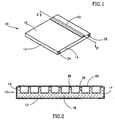
- FIG. 1 - 4 illustrate an electrophoresis disposable cassette, generally referenced 10, constructed and operative in accordance with a preferred embodiment of the present invention.
- Cassette 10 as best seen in Fig. 1, is a closed disposable cassette preferably, but not necessarily, used for a single electrophoresis test.
- Cassette 10 includes all the chemical compounds required for driving the electrophoresis separation and for enabling visualization of its results when DNA as well as RNA or protein molecules have been separated.
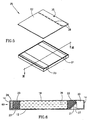
- the cassette 10 preferably comprises a three dimensional chamber 11 which is preferably substantially flat, having bottom wall and side walls, referenced 12 and 14 respectively, and a cover 16 which forms the top wall of the cassette.
- the bottom wall 12 (Fig. 4) and the cover 16 are preferably made of any suitable UV transparent material, such as the TPX plastic commercially available from MITSUI of Japan or the PMMA plastic, commercially available from Repsol Polivar S.P.A. of Rome.
- a plastic molding process is employed utilizing a Rohaglas Molding Powder, commercially available from Sidas GmbH of Damstadt, Germany.
- chamber 11 preferably comprises a gel matrix 18 which may be any suitable gel matrix for electrophoresis, such as an agarose gel or a gel made of acrylamide, a cation exchange matrix 20 and an anion exchange matrix 22, collectively referred to as the ion exchange matrices 20 and 22.
- Chamber 11 further comprises two conductive rods referenced 24 and 26, such as stainless steel rods which, when connected to an external direct current (DC) electrical power source, provide the electric field required to drive electrophoretic separation.
- rod 24 is the anode and rod 26 is the cathode.
- Chamber 11 further comprises two empty volumes 28 and 30, in which gases produced during the electrophoresis test may accumulate.
- the open cover 16 may include two vent holes 32 and 34, shown only in Fig. 3, for venting the gases accumulated in the empty volumes 28 and 30.
- a particular feature of cassette 10, as best shown in Figs. 3 and 4 is that the volume of the ion source, the ion exchange matrices 20 and 22 in the illustrated embodiment, is smaller than the volume of the gel 18 utilized as the electrophoresis separation matrix and preferably smaller than the volume of gel utilized for actual separation during an electrophoresis test.
- cassette 10 includes vent holes 32 and 34 they are sealed prior to the beginning of the electrophoretic test, and are opened just before the electrophoresis test begins and are closed again after the test is completed to substantially reduce the possibility of contamination originated therefrom.
- each of the gel 18, the ion exchange matrices 20 and 22 and the conductive rods 24 and 26 are in contact and are immersed in a relatively small amount of an agarose matrix produced and including a buffer solution, such as a TAE buffer, which facilitates the mobility of the molecules undergoing separation and of the ions provided by the ion exchange matrices 20 and 22.
- a buffer solution such as a TAE buffer
- the ions required for driving the electrophoretic separation are provided by the ion exchange matrices 20 and 22, preferably, by exchanging with protons and hydroxyl ions derived from electrolysis of H 2 O.
- a DC current is applied via rods 24 and 26 to initiate the electrolysis which in turn initiates the operation of the ion exchange matrices.
- the cation exchange matrix 20 and the anions exchange matrix 22 release the cations and anions required for driving electrophoresis separation.
- An example of a suitable cation is the Tris (+) cation and an example of a suitable anion is acetate (-) .
- the ions released by the ion exchange matrices 20 and 22 are exchanged with adsorbed protons and hydroxyl anions, respectively.
- the ions adsorbed by the ion exchange matrices 20 and 22 may also be provided by the rods 24 and 26.
- the use of the ion exchange matrices 20 and 22 provides a generally uniform pH throughout the cell since any proton buildup near the anode 24 is compensated by absorption thereof by the neighboring cation exchange matrix 20 and hydroxyl buildup near the cathode 26 is compensated by absorption thereof by the anion exchange matrix 22.
- the cation exchange matrix 20 and the anions exchange matrix 22 may be immersed in one of the materials used for preparing the gel.
- a suitable cation exchange material is the CM-25-120 Sephadex and suitable anion exchange materials are the WA-30 and the A-25-120, all of which are commercially available from Sigma Inc. of St. Louis, U.S.A.
- Cassette 10 preferably also includes wells 36 in the gel 18.
- Wells 36 are used to introduce samples of the molecules which are to undergo electrophoretic separation.
- the wells 36 may be formed by any suitable method, such as by introducing a comb like structure 40 (Fig. 2) to the gel during the assembly of the gel.
- the comb 40 is introduced to the gel via corresponding openings 38 (Fig. 1) in the cover 16.
- the openings 38 may be used as an additional space for loading the molecular samples just before the onset of the electrophoresis test after the comb 40 is removed.
- the wells 36 are covered by the comb 40 used in their preparation. This is since the comb method involves insertion of a comb structure into the gel via the openings 38 in the top cover 16, the comb being pulled out only just before the electrophoresis test.
- the cassette 10 is a closed cassette covered by the comb 40 which is removed just before the electrophoresis test itself.
- the cassette 10 also includes a source for ethidium cations which are used for ultra violet (UV) visualization of the separated DNA molecules.
- a source for ethidium cations which are used for ultra violet (UV) visualization of the separated DNA molecules.
- the cassette 10 includes an internal source for ethidium ions source.
- the cation exchange matrix 20 releases not only the TRIS cations but also ethidium cations which interact with the molecules undergoing electrophoretic separation.
- the cation exchange matrix 20 provides a continuous flux of ethidium cations during the electrophoresis test so as to stain the DNA molecules so as to enable their visualization and analysis, in situ, utilizing a suitable electrophoresis system, such as the system described with reference to Fig. 16 hereinbelow.
- the following examples which are not intended to limit the scope of the present invention, illustrate how the cation exchange matrix 20 and the anion exchange matrix 22 are prepared.
- the following example is for a cassette whose outer length, width and height are 100 millimeters (mm), 80mm and 6mm, respectively. It will be appreciated that a cassette of these outer dimensions is substantially flat.
- the cation exchange matrix 20 was prepared as follows:
- the anion exchange matrix 22 is prepared as follows:
- the cation exchange matrix 20 is prepared as follows:
- the anion exchange matrix 22 was prepared as follows:
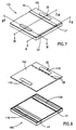
- FIG. 5 and 6 illustrate an electrophoresis cassette, generally referenced 25, constructed and operative in accordance with a second preferred embodiment of the present invention.
- Cassette 25 is generally similar in construction and operation to cassette 10 (Figs. 1 - 4), i.e. it is a closed disposable cassette preferably used for a single electrophoresis test which comprises a gel 18 and an ion exchange matrices 20 and 22. Therefore similar elements of cassettes 10 and 25 are referenced by similar reference numerals (e.g. comb 40).
- Chamber 60 comprises similar to chamber 11 a gel matrix 18 and an ion exchange matrices 20 and 22. However, chamber 60 differs from chamber 11 in construction and operation with respect to the anode and cathode and the gas accumulation and venting mechanism.
- Chamber 60 comprises two conductive strips 21 and 23 which form the cathode and anode, respectively.
- Cathode 21 is diagonally supported by a diagonal ramp 27, ramp 27 preferably forms an integral part of chamber 60.
- Anode 23 is positioned under ion exchange matrix 20 and an additional gel matrix 29 which shrinks during electrophoresis due to electroendosmosis as described in detail hereinbelow.
- Gel matrix 29 is preferably the same gel as gel matrix 18, however its gel strength is lower than that of gel 18.
- gel matrix 18 is comprised of 2% agarose while the gel matrix 29 comprises 0.3% agarose.
- cathode 21 and anode 23 are made of a conductive material that is capable of adsorbing gases produced during the electrophoretic separation process.
- cathode 21 and anode 23 are made of aluminum.
- the oxygen produced at the vicinity of anode 23 reacts with the aluminum anode to form aluminum oxide, whereby less free oxygen is produced at the anode side.
- the reduction in the volume of gas produced, together with the space created for gas accumulation by the shrinkage of gel matrix 29, alleviates the need for a vent hole in the anode side of cassette 25.
- cassette 25 may include in its cover 62 only a single vent hole 35 above empty volume 30 which is adjacent to the cathode.
- the anode is made of aluminum as described hereinabove whereas the cathode is formed of palladium or any other suitable conductive material which adsorbs hydrogen at the cathode side.
- cassette 25 is diagonally supported by ramp 27. This facilitates continuous contact between the cathode and the surface of the anion exchange matrix 22 overlying cathode 21, whereby release of gas bubbles produced at the vicinity of cathode 21 are directed towards empty volume 30.
- ramp 27 is formed as an integral part of chamber 60 and is inclined to the bottom wall 12 at an angle of about 45 degrees.
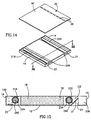
- FIG. 7 - 11 illustrate an electrophoresis cassette, generally referenced 125, constructed and operative in accordance with yet another preferred embodiment of the present invention.
- Cassette 125 similarly to cassettes 10 and 25 is a closed disposable cassette used for a single electrophoresis test and including all the chemical compounds required for driving the electrophoresis separation and for enabling visualization of its results when DNA as well as RNA or protein molecules have been separated.
- Cassette 125 comprises a three dimensional chamber 160 generally similar to chamber 60 of cassette 25 and a cover 162 generally similar to cover 62 of cassette 25. Cassette 125 differs from cassette 25 in its ion source for driving the electrophoresis separation.
- elements which are generally similar to elements of cassettes 10 and 25 are designated by similar reference numerals (e.g. gel 18).
- the body of gel 18 is disposed intermediate two spaces 120 and 122 containing a buffer solution, such as the TAE buffer solution described hereinabove.
- a buffer solution such as the TAE buffer solution described hereinabove.
- Each of volumes 120 and 122 comprises therein a closed reservoir which includes the same buffer however in a higher concentration so as to provide the ions for driving the electrophoresis separation.
- the closed reservoirs are breakable ampoules 116 and 134 including buffer solutions 124 and 132, respectively which are of higher concentration than that of volumes 120 and 122.
- the concentration of solutions 124 and 132 is fifty fold higher than that of the buffer solutions of spaces 120 and 122.
- ampoules 116 and 134 are formed of any sealed suitable material impermeable to water, such as plastic or glass, thus the concentrated buffer solutions 124 and 132 therein are not in contact with the buffer solutions filling volumes 120 and 122.
- ampoules 116 and 134 are supported by ampoule supports 106.
- the user breaks ampoules 116 and 134 so as to provide the ions in the high concentration buffers 124 and 132, respectively, in order to provide the ions required to run the electrophoresis test, preferably, after the DC current is provided to cassette 125.
- each of ampoules 116 and 134 is supported under a flexible cover 110.
- Flexible covers 110 are formed of any flexible material responsive to mechanical force, such as rubber, so as to enable breaking of ampoules 116 and 134 once pressure is applied thereon, thereby releasing their contents into buffer spaces 120 and 122 respectively.
- concentrated buffer solution 124 also contains a suitable material for DNA staining, preferably any source for ethidium cations, such as ethidium bromide so as to enable UV visualization of the separated DNA samples as described hereinabove.
- a suitable material for DNA staining preferably any source for ethidium cations, such as ethidium bromide so as to enable UV visualization of the separated DNA samples as described hereinabove.
- chamber 160 is formed of a UV transparent material.
- FIG. 12 - 15 illustrate an electrophoresis cassette, generally referenced 225, constructed and operative in accordance with yet another preferred embodiment of the present invention.
- Cassette 225 is similar to cassette 125 and similarly to cassettes 10 and 25 and 125 is a closed disposable cassette used for a single electrophoresis test and including all the chemical compounds required for driving the electrophoresis separation and for enabling visualization of its results when DNA as well as RNA or protein molecules have been separated.
- Cassette 225 is generally similar to cassette 125 in construction and operation and similar elements are referenced by similar reference numerals. Cassette 225 differs from cassette 125 in its ampoule and its mechanism for breaking it.
- Cassette 225 comprises two ampoules 216 and 234 generally similar to ampoules 116 and 134 which are capable of melting by passing an electric current therethrough.
- a conducting wire 240 is embedded in the wall of ampoules 216 and 234.
- conducting wire 240 is a high resistivity single wire having two ends 226 to which electric current in a closed circuit may be applied.
- ampoules 216 and 234 are melted just before the electrophoretic test is started by passing a current through conductive wire 240 by connecting an electrical power source to contacts 226.
- the portions of conductive wire 240 not embedded in ampoules 216 and 234 are coated with an insulating material so as to insulate them.
- Fig. 16 is a schematic isometric illustration of a system for conducting a plurality of electrophoresis tests and which is suitable for visualizing and documenting, in situ, the results thereof, constructed and operative in accordance with a preferred embodiment of the present invention.
- the system generally referenced 100, preferably comprises a holder or support housing 102 for supporting any of cassettes 10, 25, 125 or 225, a power supply 104 for providing the direct current (DC) required for driving the electrophoresis separation process, a cable 105 for connecting any of cassettes 10, 25, 125 and 225 to power supply 104 and an ultra violet (UV) light source 106 for illuminating the cassettes 10, 25, 125 or 225.
- DC direct current
- UV ultra violet
- Holder 102 preferably comprises two contact points (not shown) to which the rods 24 and 26 of the cassette 10, or strips 21 and 23 of cassettes 25, 125 or 225 are connected so as to provide thereto the electric field required for the electrophoresis separation.
- system 100 also comprises a second cable 107 for providing the current required to heat conductive wire 240 in case cassette 225 is used.
- holder 102 includes an additional pair of contacts to which contacts 226 of cassette 225 are connected so as to provide thereto the electric current required for the heating conductive wire 240.
- system 100 Another optional feature of system 100 is means for cooling any of cassettes 10, 25, 125, or 225, during the electrophoresis test, such as a flow of cooled gas, for example, liquid nitrogen, schematically illustrated by the balloon 112 and the tube 114.
- cooled gas for example, liquid nitrogen
- system 100 also comprise means for documenting the electrophoresis separation results.
- these include a camera, preferably a video camera 116 and a computer 119 operatively connected to camera 116 and executing any suitable application for image analysis of the results of the electrophoresis separation.
- both the electrophoresis test, the visualization of the results thereof and optionally the documentation and the analysis thereof are performed when the cassette is in situ, i.e in holder 102.
- cassettes 10, 25, 125 and 225 preferably include ethidium cations as described hereinabove so as to enable the visualization and thus the documentation and analysis of the electrophoresis test results.
- the holder 102 is a stand alone open box-like construction which includes a support surface 108 on which any of cassettes 10, 25, 125 or 225 is placed. Alternatively, it may include a UV transparent bottom surface.
- Another particular feature of the system 100 is that relative to prior art, a smaller number of operations is required from the user in order to conduct an electrophoresis test employing any of cassettes 10, 25, 125 or 225.
- These steps, for electrophoresis separation of DNA molecules include:
- any of the cassettes of the present invention may include a combination of the ion exchange matrix disposed at one side of the gel 18 and the closed reservoir disposed at the other end thereof.
- Another example which is within the scope of the present invention is a two dimensional cassette in which the ion sources are disposed on all four sides of gel 18.
Abstract
Description
Claims (31)
- Apparatus for conducting electrophoresis separation therein, the apparatus comprising:a housing having at least bottom (12) and side walls (14) defining a chamber, said chamber comprises, in contact therebetween:a body of gel (18) for carrying therein said electrophoresis separation;at least one ion source (20, 22) for providing ions for driving said electrophoresis, said at least one ion source having a volume smaller than the volume of said body of gel; andelectrodes (24, 26) for connecting said chamber to an external electrical power source, thereby enabling to drive said electrophoresis separation.
- Apparatus according to claim 1 wherein said at least one ion source comprises a body of ion exchange matrix.
- Apparatus according to claim 2 wherein said body of ion exchange matrix comprises:a body of cation exchange matrix for providing the cations for driving said electrophoresis separation; anda body of anion exchange matrix for providing the anions for driving said electrophoresis separation.
- Apparatus according to claim 3 wherein said cation exchange matrix is disposed at one end of said body of separating gel and said body of anion exchange matrix is disposed on a second end of said separating gel.
- Apparatus according to claim 4 wherein said cation exchange matrix exchanges protons derived from electrolysis with the cations for driving said electrophoretic separation and said anion exchange matrix exchanges hydroxyl ions derived from said electrolysis with the anions for driving said electrophoretic separation.
- Apparatus according to claim 3 wherein said cation exchange matrix and said anion exchange matrix comprise particles immersed in a support matrix.
- Apparatus according to claim 6 wherein said support matrix comprises said separating gel.
- Apparatus according to claim 3 further comprising a body of gel of low gel strength, disposed between said side wall of said chamber and said cation exchange matrix, said body of gel of low gel strength shrinking during said electrophoresis separation, thereby providing a volume in which gases produced at the vicinity of an anode of said chamber accumulates.
- Apparatus according to any of the preceding claims and also comprising a buffer solution in contact with said body of separating gel, said at least one body of ion exchange matrix and said electrodes.
- Apparatus according to claim 9 wherein said buffer is a TAE buffer, said cation exchange matrix releases Tris cations and said anion exchange matrix releases acetate anions.
- Apparatus according to claim 3 wherein said cation exchange matrix further comprises ethidium cations.
- Apparatus according to claim 1 wherein said at least one ion source comprises a closed reservoir having therein a buffer solution having higher concentration than a concentration of a buffer solution of said body of gel for carrying therein said electrophoresis separation, said closed reservoir being opened just before said electrophoresis separation for providing said ions for driving said electrophoresis separation.
- Apparatus according to claim 12 wherein said closed reservoir is a breakable ampoule.
- Apparatus according to claim 13 wherein said breakable ampoule is surrounded by a space, said space at least partially filled with said buffer solution in a concentration generally similar to that of said body of gel for carrying therein said electrophoresis separation.
- Apparatus according to claim 1 and also comprising a cover for closing said chamber, thereby providing a substantially closed apparatus.
- Apparatus according to claim 14 wherein said chamber or cover further comprise at least one opening therein for introducing at least one test sample into said body of gel.
- Apparatus according to claim 16 wherein said at least one opening is closed by a comb prior to the electrophoresis separation.
- Apparatus according to any of the previous claims wherein said chamber is transparent to ultra violet (UV) radiation.
- Apparatus according to claim 14 wherein said cover is transparent to ultra violet (UV) radiation.
- Apparatus according to claim 14 wherein said cover comprises at least one vent hole which is closed prior to said electrophoresis test and is being opened just before said electrophoresis test.
- Apparatus according to any of the preceding claims wherein said apparatus is substantially flat.
- Apparatus according to any of the previous claims wherein said apparatus is disposable.
- Apparatus according to any of the previous claims and wherein at least one of said electrodes comprises a conductive material capable of adsorbing at least part of at least one of the gases produced during said electrophoresis separation.
- Apparatus according to claim 23 wherein said at least one electrode capable of adsorbing is substantially formed from a material selected from the group consisting of aluminium and palladium.
- Apparatus according to claim 24 wherein said gases include oxygen created at the vicinity of said anode during said electrophoresis separation and reacting with said aluminium.
- Apparatus according to: claim 24 wherein said gases include hydrogen created at the vicinity of said cathode during said electrophoresis separation and wherein said hydrogen is adsorbed by said palladium.
- Apparatus according to any of the previous claims wherein said at least one electrodes comprises a strip of conductive material.
- Apparatus according to claim 27 wherein said strip of conductive material is mounted on a ramp, said ramp being inclined at an angle relative to said bottom wall, whereby gases produced at the vicinity of said strip during said electrophoresis separation are being directed to any empty volume receiving said gases.
- Apparatus according to any of the previous claims also comprising means enabling visualization of said electrophoresis separation.
- Apparatus according to claim 14 further comprising at least one empty volume for accumulating gases produced during said electrophoresis test.
- A method for producing a substantially closed cassette for conducting electrophoresis separation therein comprising the method of providing a housing having bottom and side walls defining an open chamber, assembling within said chamber in contact there between a body of gel for carrying therein said electrophoresis separation, at least one ion source for providing ions for driving said electrophoresis separation, said at least one ion source having a volume smaller than that of said body of gel and electrodes for connecting said chamber to an external electrical power source; and closing said open housing with a cover, thereby forming a substantially closed cassette capable of carrying said electrophoresis separation therein.
Priority Applications (2)
| Application Number | Priority Date | Filing Date | Title |
|---|---|---|---|
| ES04102122T ES2305661T3 (en) | 1995-04-26 | 1996-04-26 | APPARATUS AND METHOD FOR ELECTROPHORESIS. |
| EP04102122A EP1486783B1 (en) | 1995-04-26 | 1996-04-26 | Apparatus and method for electrophoresis |
Applications Claiming Priority (3)
| Application Number | Priority Date | Filing Date | Title |
|---|---|---|---|
| US08/427,917 US5582702A (en) | 1995-04-26 | 1995-04-26 | Apparatus and method for electrophoresis |
| US427917 | 1995-04-26 | ||
| PCT/US1996/005653 WO1996034276A1 (en) | 1995-04-26 | 1996-04-26 | Apparatus and method for electrophoresis |
Related Child Applications (1)
| Application Number | Title | Priority Date | Filing Date |
|---|---|---|---|
| EP04102122A Division EP1486783B1 (en) | 1995-04-26 | 1996-04-26 | Apparatus and method for electrophoresis |
Publications (3)
| Publication Number | Publication Date |
|---|---|
| EP0824689A1 EP0824689A1 (en) | 1998-02-25 |
| EP0824689A4 EP0824689A4 (en) | 1999-02-24 |
| EP0824689B1 true EP0824689B1 (en) | 2004-06-30 |
Family
ID=23696836
Family Applications (2)
| Application Number | Title | Priority Date | Filing Date |
|---|---|---|---|
| EP04102122A Expired - Lifetime EP1486783B1 (en) | 1995-04-26 | 1996-04-26 | Apparatus and method for electrophoresis |
| EP96913074A Expired - Lifetime EP0824689B1 (en) | 1995-04-26 | 1996-04-26 | Apparatus and method for electrophoresis |
Family Applications Before (1)
| Application Number | Title | Priority Date | Filing Date |
|---|---|---|---|
| EP04102122A Expired - Lifetime EP1486783B1 (en) | 1995-04-26 | 1996-04-26 | Apparatus and method for electrophoresis |
Country Status (12)
| Country | Link |
|---|---|
| US (2) | US5582702A (en) |
| EP (2) | EP1486783B1 (en) |
| JP (1) | JP4053592B2 (en) |
| AT (2) | ATE391291T1 (en) |
| AU (1) | AU706048B2 (en) |
| CA (1) | CA2219536C (en) |
| DE (2) | DE69637485T2 (en) |
| DK (1) | DK1486783T3 (en) |
| ES (1) | ES2305661T3 (en) |
| IL (1) | IL118033A (en) |
| NZ (1) | NZ306974A (en) |
| WO (1) | WO1996034276A1 (en) |
Families Citing this family (56)
| Publication number | Priority date | Publication date | Assignee | Title |
|---|---|---|---|---|
| US7824532B2 (en) * | 1995-04-26 | 2010-11-02 | Life Technologies Corporation | Apparatus and method for electrophoresis |
| US5582702A (en) * | 1995-04-26 | 1996-12-10 | Ethrog Biotechnology Ltd. | Apparatus and method for electrophoresis |
| US6379516B1 (en) | 1995-04-26 | 2002-04-30 | Ethrog Biotechnology Ltd. | Apparatus and method for electrophoresis |
| US6451192B1 (en) * | 1996-07-18 | 2002-09-17 | Cosmo Bio Co., Ltd. | Simplified electrophoresis apparatus |
| ATE397061T1 (en) | 1997-01-08 | 2008-06-15 | Invitrogen Corp | METHOD FOR PRODUCING PROTEINS |
| AU7799598A (en) * | 1997-06-09 | 1998-12-30 | Hoeffer Pharmacia Biotech, Inc. | Device for rehydration and electrophoresis of gel strips and method of using thesame |
| WO1999013987A1 (en) * | 1997-09-16 | 1999-03-25 | Life Technologies, Inc. | Gel loading adapter |
| SE9703578D0 (en) | 1997-10-01 | 1997-10-01 | Pharmacia Biotech Ab | Cassette for electrophoresis system |
| DE69924900T2 (en) * | 1998-02-16 | 2006-02-23 | Mallinckrodt, Inc. | Container for an electrophoretic gel and associated method of use |
| US6277258B1 (en) * | 1998-05-06 | 2001-08-21 | Washington State University Research Foundation | Device and method for focusing solutes in an electric field gradient |
| US6063250A (en) * | 1998-05-15 | 2000-05-16 | C.C. Imex | Running tank assembly for electrophoresis |
| US6402915B1 (en) | 1998-05-15 | 2002-06-11 | C.C. Imex | Running tank assembly for electrophoresis |
| US6156182A (en) * | 1998-11-19 | 2000-12-05 | Bio-Rad Laboratories, Inc. | Encapsulated IPG Strips |
| US6165337A (en) * | 1998-12-23 | 2000-12-26 | Shelton Scientific Manufacturing, Inc. | Semi-dry electrophoresis apparatus and method |
| US6379519B1 (en) * | 1999-09-01 | 2002-04-30 | Mirador Dna Design Inc. | Disposable thermoformed electrophoresis cassette |
| US6562213B1 (en) * | 2000-08-30 | 2003-05-13 | Ethrog Biotechnology Ltd. | Electrophoresis apparatus for simultaneous loading of multiple samples |
| CA2427022A1 (en) * | 2000-11-02 | 2002-05-10 | Gene Bio-Application Ltd. | Gel trap for electrophoresis |
| DE60220497T2 (en) | 2001-01-26 | 2008-01-31 | Biocal Technology, Inc., Irvine | OPTICAL DETECTION IN A MULTI-CHANNEL BIOSEPARATION SYSTEM |
| ATE522802T1 (en) * | 2001-01-26 | 2011-09-15 | Qiagen Sciences Llc | MULTI-CHANNEL CASSETTE FOR BIOSEPARATION |
| JP4098990B2 (en) * | 2001-02-28 | 2008-06-11 | 株式会社アドバンス | Small simple electrophoresis device |
| WO2002071024A2 (en) * | 2001-03-08 | 2002-09-12 | Ethrog Biotechnology Ltd. | Apparatus and method for electrophoresis |
| US20030032201A1 (en) * | 2001-08-10 | 2003-02-13 | Flesher Robert W. | Method and device for electrophoresis and blotting |
| WO2003062815A1 (en) * | 2002-01-18 | 2003-07-31 | Biocal Technology, Inc. | Multi-segment cartridge for bio-separation with multiplexed fluorescence detection |
| WO2004025252A2 (en) * | 2002-09-11 | 2004-03-25 | Temple University - Of The Commonwealth System Of Higher Education | Automated system for high-throughput electrophoretic separations |
| EP1680665A4 (en) * | 2003-09-19 | 2010-06-16 | Life Technologies Corp | Composite compositions for electrophoresis |
| US7781173B2 (en) * | 2003-09-25 | 2010-08-24 | Life Technologies Corporation | Homogeneous populations of molecules |
| CA2540508A1 (en) | 2003-09-30 | 2005-04-14 | Molecular Probes, Inc. | Detection of immobilized nucleic acid |
| SE0402909D0 (en) * | 2004-11-25 | 2004-11-25 | Amersham Biosciences Ab | Method for scanning gels and gels folder for use in method |
| GB0502556D0 (en) | 2005-02-08 | 2005-03-16 | Lab901 Ltd | Analysis instrument |
| US8173002B2 (en) | 2005-02-24 | 2012-05-08 | Life Technologies Corporation | Electro-blotting devices, systems, and kits, and methods for their use |
| JP4814216B2 (en) * | 2005-03-04 | 2011-11-16 | 株式会社アドバンス | Barrier structure for electrophoresis and electrophoresis apparatus |
| GB0509611D0 (en) | 2005-05-11 | 2005-06-15 | Amersham Biosciences Ab | Method and device for imaging a sample |
| US7491306B2 (en) * | 2005-07-19 | 2009-02-17 | Xiumei Sun | Apparatus for use in gel electrophoresis |
| KR100738085B1 (en) * | 2005-12-21 | 2007-07-12 | 삼성전자주식회사 | A microfluidic device for electrochemically regulating the pH of a fluid therein and method for regulating the pH of a fluid in a microfuidic device using the same |
| US20070151853A1 (en) | 2005-12-29 | 2007-07-05 | Invitrogen Corporation | Compositions and Methods for Improving Resolution of Biomolecules Separated on Polyacrylamide Gels |
| US8562802B1 (en) | 2006-02-13 | 2013-10-22 | Life Technologies Corporation | Transilluminator base and scanner for imaging fluorescent gels, charging devices and portable electrophoresis systems |
| WO2008042495A2 (en) | 2006-07-21 | 2008-04-10 | Life Technologies Corporation | Sharply resolving labeled protein molecular weight standards |
| GB0810445D0 (en) | 2008-06-06 | 2008-07-09 | Lab901 Ltd | An electrophoresis cassette |
| US8361294B2 (en) * | 2009-06-26 | 2013-01-29 | Yi Wang | Monolithic electrophoresis gel system |
| US8974651B2 (en) | 2010-04-17 | 2015-03-10 | C.C. Imex | Illuminator for visualization of fluorophores |
| GB201102385D0 (en) | 2011-02-10 | 2011-03-30 | Biocule Scotland Ltd | Two-dimensional gel electrophoresis apparatus and method |
| WO2012149180A2 (en) | 2011-04-26 | 2012-11-01 | Life Technologies Corporation | Fluorescent tracking dye |
| TWI412629B (en) * | 2011-05-23 | 2013-10-21 | Univ Tatung | Method and apparatus of electrophoretic deposition |
| IN2014DN09294A (en) * | 2012-05-31 | 2015-07-10 | Ge Healthcare Bio Sciences Ab | |
| WO2013180640A1 (en) * | 2012-05-31 | 2013-12-05 | Ge Healthcare Bio-Sciences Ab | Electrophoresis gel cassette |
| US9400260B2 (en) * | 2013-05-11 | 2016-07-26 | Man-Hee Suh | Prefabricated, self-contained gel electrophoresis module |
| USD738527S1 (en) | 2013-05-28 | 2015-09-08 | Life Technologies Corporation | Electroblotting apparatus |
| WO2015079048A1 (en) * | 2013-11-29 | 2015-06-04 | Ge Healthcare Bio-Sciences Ab | Electrophoresis system |
| US9835587B2 (en) | 2014-04-01 | 2017-12-05 | C.C. Imex | Electrophoresis running tank assembly |
| EP3186356B1 (en) * | 2014-07-30 | 2022-02-16 | Case Western Reserve University | Biochips to diagnose hemoglobin disorders and monitor blood cells |
| CN106345220B (en) * | 2015-07-13 | 2023-04-28 | 中国农业科学院兰州兽医研究所 | Application of adsorption device in adsorption of volatilized ethidium bromide |
| KR102291911B1 (en) | 2016-09-08 | 2021-08-23 | 헤멕스 헬스, 인크. | Diagnostic systems and methods |
| WO2020264182A1 (en) | 2019-06-25 | 2020-12-30 | Hemex Health, Inc. | Diagnostics systems and methods |
| WO2023019105A1 (en) | 2021-08-08 | 2023-02-16 | Keydev Inc. | Cartridge gel electrophoresis device for separating biomolecules |
| WO2023122056A1 (en) * | 2021-12-21 | 2023-06-29 | Life Technologies Holdings Pte Limited | Electrophoresis system and methods |
| CN114486272B (en) * | 2021-12-24 | 2023-09-15 | 广西玉柴机器股份有限公司 | Whole vehicle carbon accumulation test method of loader |
Family Cites Families (10)
| Publication number | Priority date | Publication date | Assignee | Title |
|---|---|---|---|---|
| US3715295A (en) * | 1971-09-02 | 1973-02-06 | Tlc Corp | Disposable electrophoresis unit |
| US4323439A (en) * | 1979-12-31 | 1982-04-06 | The Regents Of The University Of California | Method and apparatus for dynamic equilibrium electrophoresis |
| SE452853B (en) * | 1986-02-13 | 1987-12-21 | Pharmacia Ab | WAY TO SUPPLY BUFFER SOLUTIONS FOR ELECTROPHORETIC SEPARATION |
| US4892639A (en) * | 1987-07-17 | 1990-01-09 | Helena Laboratories Corporation | Electrophoresis plate and method of making same |
| US5006473A (en) * | 1988-08-09 | 1991-04-09 | Abbott Laboratories | Electrophoresis method using vesicles |
| US5045164A (en) * | 1990-05-23 | 1991-09-03 | Helena Laboratories Corporation | Electrophoresis plate for diverting generated fluid |
| US5209831A (en) * | 1991-06-14 | 1993-05-11 | Macconnell William P | Bufferless electrophoresis system and method |
| FR2677894B1 (en) * | 1991-06-20 | 1993-10-15 | Bioprobe Systems | ELECTROPHORESIS DEVICE. |
| US5411657A (en) * | 1993-09-14 | 1995-05-02 | Leka; George T. | Molded plastic electrophoresis cassettes |
| US5582702A (en) * | 1995-04-26 | 1996-12-10 | Ethrog Biotechnology Ltd. | Apparatus and method for electrophoresis |
-
1995
- 1995-04-26 US US08/427,917 patent/US5582702A/en not_active Expired - Lifetime
-
1996
- 1996-04-25 IL IL11803396A patent/IL118033A/en not_active IP Right Cessation
- 1996-04-26 US US08/639,869 patent/US5865974A/en not_active Expired - Lifetime
- 1996-04-26 CA CA002219536A patent/CA2219536C/en not_active Expired - Lifetime
- 1996-04-26 ES ES04102122T patent/ES2305661T3/en not_active Expired - Lifetime
- 1996-04-26 AT AT04102122T patent/ATE391291T1/en not_active IP Right Cessation
- 1996-04-26 AU AU55693/96A patent/AU706048B2/en not_active Ceased
- 1996-04-26 WO PCT/US1996/005653 patent/WO1996034276A1/en active IP Right Grant
- 1996-04-26 JP JP53264896A patent/JP4053592B2/en not_active Expired - Lifetime
- 1996-04-26 DE DE69637485T patent/DE69637485T2/en not_active Expired - Lifetime
- 1996-04-26 NZ NZ306974A patent/NZ306974A/en not_active IP Right Cessation
- 1996-04-26 EP EP04102122A patent/EP1486783B1/en not_active Expired - Lifetime
- 1996-04-26 AT AT96913074T patent/ATE270428T1/en not_active IP Right Cessation
- 1996-04-26 DE DE69632820T patent/DE69632820T2/en not_active Expired - Lifetime
- 1996-04-26 DK DK04102122T patent/DK1486783T3/en active
- 1996-04-26 EP EP96913074A patent/EP0824689B1/en not_active Expired - Lifetime
Also Published As
| Publication number | Publication date |
|---|---|
| DE69637485T2 (en) | 2008-11-27 |
| CA2219536C (en) | 2007-01-09 |
| IL118033A (en) | 2000-02-29 |
| AU706048B2 (en) | 1999-06-10 |
| WO1996034276A1 (en) | 1996-10-31 |
| NZ306974A (en) | 1999-02-25 |
| ES2305661T3 (en) | 2008-11-01 |
| ATE270428T1 (en) | 2004-07-15 |
| JPH11505325A (en) | 1999-05-18 |
| AU5569396A (en) | 1996-11-18 |
| DE69632820T2 (en) | 2005-07-07 |
| ATE391291T1 (en) | 2008-04-15 |
| DE69637485D1 (en) | 2008-05-15 |
| US5865974A (en) | 1999-02-02 |
| CA2219536A1 (en) | 1996-10-31 |
| IL118033A0 (en) | 1996-08-04 |
| EP0824689A1 (en) | 1998-02-25 |
| DK1486783T3 (en) | 2008-08-04 |
| DE69632820D1 (en) | 2004-08-05 |
| EP0824689A4 (en) | 1999-02-24 |
| EP1486783B1 (en) | 2008-04-02 |
| EP1486783A1 (en) | 2004-12-15 |
| US5582702A (en) | 1996-12-10 |
| JP4053592B2 (en) | 2008-02-27 |
Similar Documents
| Publication | Publication Date | Title |
|---|---|---|
| EP0824689B1 (en) | Apparatus and method for electrophoresis | |
| US6379516B1 (en) | Apparatus and method for electrophoresis | |
| CA2124345C (en) | Gel electrophoresis sample applicator/retriever | |
| EP1325316B1 (en) | Electrophoresis apparatus for simultaneous loading of multiple samples | |
| US20110011741A1 (en) | Apparatus and method for electrophoresis | |
| US20020100690A1 (en) | Electrophoresis system | |
| US4622124A (en) | Device for horizontal electroblotting | |
| US20020134680A1 (en) | Apparatus and method for electrophoresis | |
| JP2008539443A (en) | Electrophoretic method with parallel and simultaneous separation | |
| CA2181141C (en) | Notched spacer for slab-gel electrophoresis | |
| JPH0943196A (en) | Electrophoresis device | |
| AU2001293500B2 (en) | Electrophoresis system | |
| AU2002236183A1 (en) | Apparatus and method for electrophoresis | |
| AU2001293500A1 (en) | Electrophoresis system | |
| IL190930A (en) | Electrophoresis apparatus for simultaneous loading of multiple samples | |
| IL154643A (en) | Electrophoresis apparatus for simultaneous loading of multiple samples |
Legal Events
| Date | Code | Title | Description |
|---|---|---|---|
| PUAI | Public reference made under article 153(3) epc to a published international application that has entered the european phase |
Free format text: ORIGINAL CODE: 0009012 |
|
| 17P | Request for examination filed |
Effective date: 19971027 |
|
| AK | Designated contracting states |
Kind code of ref document: A1 Designated state(s): AT BE CH DE DK ES FR GB GR IE IT LI NL SE |
|
| A4 | Supplementary search report drawn up and despatched |
Effective date: 19990113 |
|
| AK | Designated contracting states |
Kind code of ref document: A4 Designated state(s): AT BE CH DE DK ES FR GB GR IE IT LI NL SE |
|
| 17Q | First examination report despatched |
Effective date: 20020412 |
|
| GRAP | Despatch of communication of intention to grant a patent |
Free format text: ORIGINAL CODE: EPIDOSNIGR1 |
|
| GRAS | Grant fee paid |
Free format text: ORIGINAL CODE: EPIDOSNIGR3 |
|
| GRAA | (expected) grant |
Free format text: ORIGINAL CODE: 0009210 |
|
| AK | Designated contracting states |
Kind code of ref document: B1 Designated state(s): AT BE CH DE DK ES FR GB GR IE IT LI NL SE |
|
| PG25 | Lapsed in a contracting state [announced via postgrant information from national office to epo] |
Ref country code: NL Free format text: LAPSE BECAUSE OF FAILURE TO SUBMIT A TRANSLATION OF THE DESCRIPTION OR TO PAY THE FEE WITHIN THE PRESCRIBED TIME-LIMIT Effective date: 20040630 Ref country code: IT Free format text: LAPSE BECAUSE OF FAILURE TO SUBMIT A TRANSLATION OF THE DESCRIPTION OR TO PAY THE FEE WITHIN THE PRE;WARNING: LAPSES OF ITALIAN PATENTS WITH EFFECTIVE DATE BEFORE 2007 MAY HAVE OCCURRED AT ANY TIME BEFORE 2007. THE CORRECT EFFECTIVE DATE MAY BE DIFFERENT FROM THE ONE RECORDED.SCRIBED TIME-LIMIT Effective date: 20040630 Ref country code: AT Free format text: LAPSE BECAUSE OF FAILURE TO SUBMIT A TRANSLATION OF THE DESCRIPTION OR TO PAY THE FEE WITHIN THE PRESCRIBED TIME-LIMIT Effective date: 20040630 |
|
| REG | Reference to a national code |
Ref country code: GB Ref legal event code: FG4D Ref country code: CH Ref legal event code: EP |
|
| REG | Reference to a national code |
Ref country code: IE Ref legal event code: FG4D |
|
| REF | Corresponds to: |
Ref document number: 69632820 Country of ref document: DE Date of ref document: 20040805 Kind code of ref document: P |
|
| PG25 | Lapsed in a contracting state [announced via postgrant information from national office to epo] |
Ref country code: GR Free format text: LAPSE BECAUSE OF FAILURE TO SUBMIT A TRANSLATION OF THE DESCRIPTION OR TO PAY THE FEE WITHIN THE PRESCRIBED TIME-LIMIT Effective date: 20040930 Ref country code: DK Free format text: LAPSE BECAUSE OF FAILURE TO SUBMIT A TRANSLATION OF THE DESCRIPTION OR TO PAY THE FEE WITHIN THE PRESCRIBED TIME-LIMIT Effective date: 20040930 |
|
| PG25 | Lapsed in a contracting state [announced via postgrant information from national office to epo] |
Ref country code: ES Free format text: LAPSE BECAUSE OF FAILURE TO SUBMIT A TRANSLATION OF THE DESCRIPTION OR TO PAY THE FEE WITHIN THE PRESCRIBED TIME-LIMIT Effective date: 20041011 |
|
| REG | Reference to a national code |
Ref country code: SE Ref legal event code: TRGR |
|
| REG | Reference to a national code |
Ref country code: CH Ref legal event code: NV Representative=s name: DR. GRAF & PARTNER INTELLECTUAL PROPERTY |
|
| NLV1 | Nl: lapsed or annulled due to failure to fulfill the requirements of art. 29p and 29m of the patents act | ||
| PG25 | Lapsed in a contracting state [announced via postgrant information from national office to epo] |
Ref country code: IE Free format text: LAPSE BECAUSE OF NON-PAYMENT OF DUE FEES Effective date: 20050426 |
|
| ET | Fr: translation filed | ||
| PLBE | No opposition filed within time limit |
Free format text: ORIGINAL CODE: 0009261 |
|
| STAA | Information on the status of an ep patent application or granted ep patent |
Free format text: STATUS: NO OPPOSITION FILED WITHIN TIME LIMIT |
|
| 26N | No opposition filed |
Effective date: 20050331 |
|
| REG | Reference to a national code |
Ref country code: CH Ref legal event code: PFA Owner name: ETHROG BIOTECHNOLOGY LTD. Free format text: ETHROG BIOTECHNOLOGY LTD.#39#MOSHAV GANOT 50293 (IL) -TRANSFER TO- ETHROG BIOTECHNOLOGY LTD.#39#MOSHAV GANOT 50293 (IL) |
|
| PGFP | Annual fee paid to national office [announced via postgrant information from national office to epo] |
Ref country code: SE Payment date: 20110425 Year of fee payment: 16 |
|
| REG | Reference to a national code |
Ref country code: SE Ref legal event code: EUG |
|
| PG25 | Lapsed in a contracting state [announced via postgrant information from national office to epo] |
Ref country code: SE Free format text: LAPSE BECAUSE OF NON-PAYMENT OF DUE FEES Effective date: 20120427 |
|
| REG | Reference to a national code |
Ref country code: FR Ref legal event code: PLFP Year of fee payment: 20 |
|
| PGFP | Annual fee paid to national office [announced via postgrant information from national office to epo] |
Ref country code: DE Payment date: 20150422 Year of fee payment: 20 Ref country code: GB Payment date: 20150422 Year of fee payment: 20 Ref country code: CH Payment date: 20150414 Year of fee payment: 20 |
|
| PGFP | Annual fee paid to national office [announced via postgrant information from national office to epo] |
Ref country code: BE Payment date: 20150413 Year of fee payment: 20 Ref country code: FR Payment date: 20150408 Year of fee payment: 20 |
|
| REG | Reference to a national code |
Ref country code: DE Ref legal event code: R071 Ref document number: 69632820 Country of ref document: DE |
|
| REG | Reference to a national code |
Ref country code: CH Ref legal event code: PL |
|
| REG | Reference to a national code |
Ref country code: GB Ref legal event code: PE20 Expiry date: 20160425 |
|
| PG25 | Lapsed in a contracting state [announced via postgrant information from national office to epo] |
Ref country code: GB Free format text: LAPSE BECAUSE OF EXPIRATION OF PROTECTION Effective date: 20160425 |