EP0824603B1 - Device for vapour-depositing a material on high surface area substrates - Google Patents
Device for vapour-depositing a material on high surface area substrates Download PDFInfo
- Publication number
- EP0824603B1 EP0824603B1 EP96915075A EP96915075A EP0824603B1 EP 0824603 B1 EP0824603 B1 EP 0824603B1 EP 96915075 A EP96915075 A EP 96915075A EP 96915075 A EP96915075 A EP 96915075A EP 0824603 B1 EP0824603 B1 EP 0824603B1
- Authority
- EP
- European Patent Office
- Prior art keywords
- substrate
- evaporation
- source
- movement
- enclosure
- Prior art date
- Legal status (The legal status is an assumption and is not a legal conclusion. Google has not performed a legal analysis and makes no representation as to the accuracy of the status listed.)
- Expired - Lifetime
Links
- ZAGHKONXGGSVDV-UHFFFAOYSA-N CCCCC1CCCC1 Chemical compound CCCCC1CCCC1 ZAGHKONXGGSVDV-UHFFFAOYSA-N 0.000 description 1
Images


Classifications
-
- H—ELECTRICITY
- H01—ELECTRIC ELEMENTS
- H01J—ELECTRIC DISCHARGE TUBES OR DISCHARGE LAMPS
- H01J9/00—Apparatus or processes specially adapted for the manufacture, installation, removal, maintenance of electric discharge tubes, discharge lamps, or parts thereof; Recovery of material from discharge tubes or lamps
- H01J9/02—Manufacture of electrodes or electrode systems
- H01J9/022—Manufacture of electrodes or electrode systems of cold cathodes
- H01J9/025—Manufacture of electrodes or electrode systems of cold cathodes of field emission cathodes
-
- C—CHEMISTRY; METALLURGY
- C23—COATING METALLIC MATERIAL; COATING MATERIAL WITH METALLIC MATERIAL; CHEMICAL SURFACE TREATMENT; DIFFUSION TREATMENT OF METALLIC MATERIAL; COATING BY VACUUM EVAPORATION, BY SPUTTERING, BY ION IMPLANTATION OR BY CHEMICAL VAPOUR DEPOSITION, IN GENERAL; INHIBITING CORROSION OF METALLIC MATERIAL OR INCRUSTATION IN GENERAL
- C23C—COATING METALLIC MATERIAL; COATING MATERIAL WITH METALLIC MATERIAL; SURFACE TREATMENT OF METALLIC MATERIAL BY DIFFUSION INTO THE SURFACE, BY CHEMICAL CONVERSION OR SUBSTITUTION; COATING BY VACUUM EVAPORATION, BY SPUTTERING, BY ION IMPLANTATION OR BY CHEMICAL VAPOUR DEPOSITION, IN GENERAL
- C23C14/00—Coating by vacuum evaporation, by sputtering or by ion implantation of the coating forming material
- C23C14/22—Coating by vacuum evaporation, by sputtering or by ion implantation of the coating forming material characterised by the process of coating
- C23C14/24—Vacuum evaporation
- C23C14/243—Crucibles for source material
-
- C—CHEMISTRY; METALLURGY
- C23—COATING METALLIC MATERIAL; COATING MATERIAL WITH METALLIC MATERIAL; CHEMICAL SURFACE TREATMENT; DIFFUSION TREATMENT OF METALLIC MATERIAL; COATING BY VACUUM EVAPORATION, BY SPUTTERING, BY ION IMPLANTATION OR BY CHEMICAL VAPOUR DEPOSITION, IN GENERAL; INHIBITING CORROSION OF METALLIC MATERIAL OR INCRUSTATION IN GENERAL
- C23C—COATING METALLIC MATERIAL; COATING MATERIAL WITH METALLIC MATERIAL; SURFACE TREATMENT OF METALLIC MATERIAL BY DIFFUSION INTO THE SURFACE, BY CHEMICAL CONVERSION OR SUBSTITUTION; COATING BY VACUUM EVAPORATION, BY SPUTTERING, BY ION IMPLANTATION OR BY CHEMICAL VAPOUR DEPOSITION, IN GENERAL
- C23C14/00—Coating by vacuum evaporation, by sputtering or by ion implantation of the coating forming material
- C23C14/22—Coating by vacuum evaporation, by sputtering or by ion implantation of the coating forming material characterised by the process of coating
- C23C14/50—Substrate holders
- C23C14/505—Substrate holders for rotation of the substrates
Definitions
- the present invention relates in a way general to the deposition of material by evaporation on a large substrate.
- An application is the realization of microtip electron sources using electronic emission by field effect, said sources being large.
- These electron sources are, for example, used in visualization devices by cathodoluminescence excited by field emission, and especially in large flat screens (of the order of a square meter).
- Figure 1 shows an already developed structure, comprising on a substrate 6 surmounted by an insulator 7, a cathode conductor system 8, a layer resistive 9, grids 10a superimposed in the form crossed with an intermediate insulator 12 and a layer 23, for example nickel, deposited on the surface for serve as a mask during the operations of making microtips.
- This layer 23 of nickel, the grids 10a and the insulator 12 are drilled with holes 16 in the background of which it is a question of coming to deposit the futures microtips made of a conductive metal in electrical connection with the cathode electrode 8 to through the resistive layer 9.
- the deposition step of the molybdenum layer 18a is conventionally carried out by evaporation of molybdenum heated in a crucible and condensation of steam from molybdenum on the substrate covered with the structure stacked 7, 8, 9, 12, 10a and 23, pierced with holes 16.
- FIG. 4 A conventional evaporator is illustrated in FIG. 4.
- the material to be evaporated is heated in a source crucible 30.
- the substrates 33-1, 33-2, 33-3 are positioned on a substrate holder 31 and rotated on them- same, around an axis 34-1, 34-2, 34-3.
- the substrate holder 31 is placed opposite the crucible 30 and it is itself rotated about the axis 34-2. Evaporation takes place under vacuum at around 10 -5 -10 -6 mbar in an enclosure 35 pumped by a suitable pumping system 36.
- the substrate holder 31 has a shape adapted so that the substrates 33 receive the vapor in quasi-normal incidence with a maximum angle ⁇ max .
- This device is well suited for carrying out deposits on small or medium-sized substrates (at most a few tens of cm).
- the angle of incidence of the vapor ⁇ being very small (a few degrees), it is almost impossible to envisage depositing on a substrate a diagonal meter, the deposition speed being much too weak for an industrial process.
- the document FR-2 701 601 describes a first device for producing microtip sources, also called "ICB device”.
- a crucible is heated by a heating element and the vaporized material is then partially ionized, which leads to the formation of clusters which are accelerated.
- This type of device is not suitable for depositing on large substrates area.
- a second device includes a crucible with a plurality of nozzles through which a vapor is discharged into a vacuum box, in which it is ionized then accelerated.
- this document proposes to increase the ratio L / r where L is the thickness of the crucible and r the diameter of the nozzles.
- this type of device is incompatible with industrial production, especially on large substrates.
- the nozzles can be gradually blocked by parasitic deposits of matter. If the L / r ratio is increased, in order to increase the directivity, this problem becomes even more acute, since the vapors pass through the nozzles over a longer length important, while the latter have a diameter weaker. This also results in variations in flow rate of evaporated material.
- the object of the invention is to resolve the above problem, that is to say to offer a simple device for depositing on large surface substrates, and allowing maintain an angle of incidence of the vapor relatively small and sufficient deposition rate for an industrial process.
- the sources are placed directly opposite of the substrate: they see the substrate directly or a portion of it.
- Means for channeling the vapors emitted can be covers or walls separating the sources each other.
- the caches form compartments inside the enclosure, each source of evaporation being arranged in a compartment.
- These covers or walls can be vertical.
- the covers or walls can form cells having, at least in part, a frustoconical shape.
- a substrate holder allows mount a substrate near one end of the walls.
- a subproblem is to improve the consistency of the deposit on the substrate.
- These consistency issues may in particular appear due to the means of vapor channeling.
- these means have the form of covers or walls, marks defining areas masked by these means can appear on the substrate.
- Non-uniformity can also be due to varying deposition rates from one point to another on the substrate.
- a device comprises in in addition to means for moving the substrate, so as to pass different parts of the substrate successively before the different sources.
- These means can be means for generate and / or combine rotational movements and / or translation in a plane.
- the movement can be a planetary rotation movement of the substrate.
- a combined movement of rotation and translation around an axis, called the central axis of the evaporation system, allows to limit advantageously the lateral dimensions of the system evaporation. Indeed, in this case, the total area described by the substrate is minimized.
- Such movement can be ensured by a two interlocking gears system rotating in one same plane and around a fixed gear.
- the movement is provided by a gear kept at a constant distance from a wheel fixed tooth, a toothed belt or a chain surrounding the fixed gear and the gear.
- the means for channeling the vapors emitted by each source define, with this source, a cell, the surface swept by the moving substrate in this cell presenting, in a plane perpendicular to the direction of evaporation in this cell, a center of symmetry, the source being placed on an axis perpendicular to the surface swept by the substrate and passing through this center of symmetry.
- the substrate is a substrate of a microtip emissive system, the microtips being carried out by the evaporation step.
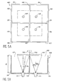
- FIG. 5A and 5B respectively represent a view of above and a sectional view of a device according to the invention.
- This device essentially consists of an enclosure 43 which, in the example illustrated in the figures, has an approximately square section. This enclosure is delimited by walls 52, 53, ..., 59. This enclosure is divided into four compartments by walls 48, 49, 50, 51. At the bottom of each of these compartments is a source of evaporation 40 , 42, 44, 46. A surface or substrate 60 can be introduced into the top of the enclosure 43, and mounted on a substrate holder (not shown in the figure) so that the deposition surface is located a distance h from the bottom of the enclosure 43. The presence of the various vertical walls makes it possible to prevent material from being evaporated on the surface of the substrate with an angle greater than the angle ⁇ 0 shown in FIG. 5B.
- the above example is limited to four sources evaporation. It is also possible to realize an enclosure 43 comprising two, three, five or more five sources of evaporation, as required. Through elsewhere, the enclosure 43 is equipped with a device for pumping (not shown in the figures) allowing to ensure a certain vacuum during the operation evaporation.
- the enclosure which has been described presents vertical walls, arranged perpendicularly between them and defining the compartments approximately cubic. It is clear that the dimensions of the different walls can be as well as the distribution of the compartments to inside the same volume of an enclosure. So, we shown in Figures 6A, 6B, 6C different possible speaker shapes and different possible wall distributions inside the enclosure.
- Figure 6A is a top view of a enclosure 62 having a substantially external shape identical to that of enclosure 43 of FIGS. 5A and 5B. Inside, walls 64, 66 are arranged in diagonal, a source of evaporation being arranged at the bottom of each of the four compartments as well delimited. Eight compartments can be made in introducing additional walls 68, 70, and four additional sources of evaporation.
- the device of FIG. 6B comprises an enclosure having overall the shape of a cylinder 72 and a certain number of walls 74, 76, 78, 80 delimiting sectors cylindrical inside the enclosure 72. A source at the bottom of each sector cylindrical.
- FIG. 6C represents an enclosure with inside which compartments 82, 84, 86, 88 of frustoconical shape are made, the different walls inside the enclosure no longer arranged vertically as in the examples previous.
- the walls delimiting compartments inside the enclosure can form cells with a cylindrical symmetry with polygonal base (this is the case Figures 5A, 6A, 6B) or cells having a partially frustoconical shape.
- Each source is located inside a compartment.
- Each compartment has an opening 61, 63 ( Figure 5B), 65, 67, 69, 71 ( Figure 6C) near which is the substrate.
- the substrate is located near one end of the walls.
- uniformity may be due to deposition speed differences between different points of a same substrate.
- this deposit speed gap can be a real problem since the total deposit time will be conditioned by the time required to cover areas where speed deposit is the lowest. This has the consequence increased manufacturing time and wastage of a lot of evaporated material. The latter is found then in overthickness in high speed areas deposit and on the walls of the evaporation system.
- the uniformity therefore varies as the cos n + 3 ⁇ of the angle ⁇ of evaporation.
- This movement improves the uniformity of deposit while limiting the lateral dimensions of the system. On the other hand, it helps prevent areas masked by the caches on the substrate.
- a substrate 112 of shape approximately square, is arranged so asymmetrical compared to the different compartments.
- the planetary movement of the substrate is a combination of a rotational movement of the substrate around the central axis of the system and a movement of rotation of the substrate around an axis perpendicular to its plan (passing for example through its center symmetry, if the substrate has such a center of symmetry).
- the substrate holder 99 is fixed on a gear represented in FIG. 8C by the reference 97 so that, for example, the center of the substrate C ( Figure 8A) coincides with the center (axis) of this gear.
- a fixed gear 96 of the same diameter that this gear 97 and having the same number of teeth and the same pitch between the teeth is fixed on axis 102 of the evaporation system.
- a second gear 95 having the same pitch between the teeth, connects the center gear C to the fixed gear of center O.
- the two gears 95 and 97 are connected to a support arm 98, for example, using bearings balls, to ensure their mobility.
- This support arm 98 rotates around the axis of the fixed gear 96, training 100 will be done for example using a engine.
- This system therefore allows to rotate-translate the substrate 112 around the center O of the evaporation system.
- Any other mechanical system can be used, which allows to obtain the same movement; for example as illustrated in FIG. 8E, it is possible to delete the gear 95 of Figures 8C and 8D and replace with a toothed belt 105 which surrounds the fixed gear 96 and gear 97.
- each source of evaporation in each compartment on an axis perpendicular to the surface to be coated and passing through this center of symmetry.
- the uniformity of the deposit can be calculated by summing the contributions of four sources of evaporation on the substrate. We calculates for example the ratio between the average speed of deposit at a point and the average speed of deposit at center of the square substrate.
- Figures 9 to 11 correspond to a substrate still and serve as a reference for comparison.
- the height of the system remains small in comparison with the 3.16m of the prior art system ( Figure 4), value which has been calculated in the introduction to this application.
- the value of h varies from lm to 2m in the examples given, depending on the configuration (angle ⁇ and distance OC). This range of heights (1-2 meters) is quite made acceptable to those skilled in the art, the limitation is located around 2 meters in height. He will be of course better to minimize this height, for example by accepting a higher tolerance large on the angle ⁇ (for example up to 15 °).
- microdot repositories to make sources of electrons, for example a source such as that described above, in conjunction with Figures 1 to 3.
- the invention therefore also relates to a method to deposit on large surfaces, this process of introducing the surface, or substrate, in a device as described above, according to the invention.
- a substrate into the evaporation device having the structure described above in connection with the figure 1.
Description
La présente invention se rapporte d'une manière générale au dépôt de matériau par évaporation sur un substrat de grande taille. Une application est la réalisation de sources d'électrons à micropointes utilisant l'émission électronique par effet de champ, lesdites sources étant de grande taille.The present invention relates in a way general to the deposition of material by evaporation on a large substrate. An application is the realization of microtip electron sources using electronic emission by field effect, said sources being large.
Ces sources d'électrons sont, par exemple, utilisées dans les dispositifs de visualisation par cathodoluminescence excitée par émission de champ, et en particulier dans les écrans plats de grande taille (de l'ordre du mètre carré).These electron sources are, for example, used in visualization devices by cathodoluminescence excited by field emission, and especially in large flat screens (of the order of a square meter).
Un système émissif à micropointes et son procédé de fabrication sont décrits en détail par exemple dans le document FR-A-2 593 953 du 24/01/1986 ou dans le document FR-A-2 663 462 du 13/06/1990. On commencera d'abord par rappeler la technique connue de fabrication de telles micropointes dans une structure de ce genre, telle qu'elle ressort du document précité en se référant aux figures 1, 2 et 3 ci-jointes.An emissive microtip system and its manufacturing process are described in detail by example in document FR-A-2 593 953 of 01/24/1986 or in document FR-A-2 663 462 of 06/13/1990. We will begin by recalling the known technique of manufacture of such microtips in a structure of this kind, as it appears from the aforementioned document with reference to Figures 1, 2 and 3 attached.
La figure 1 montre une structure déjà élaborée,
comprenant sur un substrat 6 surmonté d'un isolant 7,
un système de conducteurs cathodiques 8, une couche
résistive 9, des grilles 10a superposées sous forme
croisée avec un isolant intermédiaire 12 et une couche
23, par exemple de nickel, déposée en surface pour
servir de masque lors des opérations de réalisation des
micropointes. Cette couche 23 de nickel, les grilles
10a et l'isolant 12 sont percés de trous 16, dans le
fond desquels il s'agit de venir déposer les futures
micropointes constituées d'un métal conducteur en
liaison électrique avec l'électrode cathodique 8 à
travers la couche résistive 9.Figure 1 shows an already developed structure,
comprising on a
Pour la réalisation des micropointes, on s'y
prend de la façon suivante, en se référant à la figure
2. On commence d'abord par effectuer par exemple le
dépôt d'une couche en molybdène 18a sur l'ensemble de
la structure. Cette couche 18a présente une épaisseur
environ de 1,8 µm. Elle est déposée sous incidence
normale par rapport à la surface de la structure ;
cette technique de dépôt permet d'obtenir des cônes 18
en molybdène logés dans les trous 16 ayant une hauteur
de 1,2 à 1,5 µm. On réalise ensuite la dissolution
sélective de la couche de nickel 23 par un procédé
électrochimique de façon à dégager, comme représenté
sur la figure 3, les grilles par exemple en niobium 10a
perforées et à faire apparaítre les micropointes 18
émettrices d'électrons.For the realization of microtips, we
takes in the following way, referring to the figure
2. We start first by performing for example the
deposition of a
A quelques variantes technologiques près, la méthode connue ainsi décrite en se référant aux figures 1, 2 et 3 est toujours celle que l'on applique jusqu'à ce jour pour réaliser les micropointes des systèmes à cathode émissive.With a few technological variants, the known method thus described with reference to the figures 1, 2 and 3 is always the one that we apply until today to realize the microtips of the systems to emissive cathode.
L'étape de dépôt de la couche en molybdène 18a
est réalisée classiquement par évaporation de molybdène
chauffé dans un creuset et condensation de la vapeur de
molybdène sur le substrat recouvert de la structure
empilée 7, 8, 9, 12, 10a et 23, percée de trous 16.The deposition step of the
Pour obtenir des pointes 18 dans les trous 16,
la vapeur doit arriver en incidence quasi-normale sur
la surface de la structure précédemment décrite, par
exemple sous un angle compris entre =0 (incidence
normale) et max=9°. Dans le cas contraire, le matériau
évaporé risque de couvrir les parois des trous 16 et de
créer des courts-circuits entre les électrodes 10a et
les couches 8 et 9, ou bien il risque de remplir les
trous sans créer de pointes.To obtain
Un évaporateur classique est illustré sur la
figure 4. Le matériau à évaporer est chauffé dans un
creuset source 30. Les substrats 33-1, 33-2, 33-3 sont
positionnés sur un porte-substrats 31 et entraínés en
rotation sur eux-mêmes, autour d'un axe 34-1, 34-2, 34-3.
Le porte-substrats 31 est placé en face du creuset
30 et il est lui-même en rotation autour de l'axe 34-2.
L'évaporation se fait sous vide aux alentours de
10-5-10-6 mbar dans une enceinte 35 pompée par un
système de pompage adapté 36.A conventional evaporator is illustrated in FIG. 4. The material to be evaporated is heated in a
Dans le cas du dépôt de micropointes, le porte-substrats
31 a une forme adaptée pour que les substrats
33 reçoivent la vapeur en incidence quasi-normale avec
un angle maximum max.In the case of microtip deposition, the
Ce dispositif convient bien pour effectuer des dépôts sur des substrats de taille petite ou moyenne (au maximum quelques dizaines de cm).This device is well suited for carrying out deposits on small or medium-sized substrates (at most a few tens of cm).
Des problèmes apparaissent quant on augmente la taille des substrats.Problems arise when increasing the size of substrates.
Ainsi, si on considère le cas de la figure 4,
où le substrat 33-2 est placé en face de la source 30,
à une distance h, on a alors h =
En résumé, l'angle d'incidence de la vapeur : étant très petit (quelques degrés), il est quasiment impossible d'envisager le dépôt sur un substrat d'un mètre de diagonale, la vitesse de dépôt étant beaucoup trop faible pour un procédé industriel.In summary, the angle of incidence of the vapor: being very small (a few degrees), it is almost impossible to envisage depositing on a substrate a diagonal meter, the deposition speed being much too weak for an industrial process.
Le document FR-2 701 601 décrit un premier dispositif pour réaliser des sources à micropointes, encore appelé "appareil ICB". Un creuset est chauffé par un élément de chauffage et la matière vaporisée est ensuite partiellement ionisée, ce qui conduit à la formation d'amas qui sont accélérés.The document FR-2 701 601 describes a first device for producing microtip sources, also called "ICB device". A crucible is heated by a heating element and the vaporized material is then partially ionized, which leads to the formation of clusters which are accelerated.
Ce type de dispositif n'est pas adapté à la réalisation de dépôts sur des substrats de grande surface.This type of device is not suitable for depositing on large substrates area.
Un second dispositif est également décrit dans ce document, et comporte un creuset muni d'une pluralité de buses à travers lesquelles une vapeur est déchargée dans un caisson à vide, dans lequel elle est ionisée puis accélérée. Pour améliorer la directivité, ce document propose d'accroítre le rapport L / r où L est l'épaisseur du creuset et r le diamètre des buses.A second device is also described in this document, and includes a crucible with a plurality of nozzles through which a vapor is discharged into a vacuum box, in which it is ionized then accelerated. To improve directivity, this document proposes to increase the ratio L / r where L is the thickness of the crucible and r the diameter of the nozzles.
Cependant, ce type de dispositif est incompatible avec une production industrielle, notamment sur des substrats de grande taille. En particulier, les buses peuvent être progressivement bouchées par des dépôts parasites de matière. Si le rapport L / r est accru, afin d'accroítre la directivité, ce problème devient encore plus aigu, puisque les vapeurs traversent les buses sur une longueur plus importante, tandis que ces dernières ont un diamètre plus faible. Il en résulte, en outre, des variations de débit de la matière évaporée. However, this type of device is incompatible with industrial production, especially on large substrates. In particular, the nozzles can be gradually blocked by parasitic deposits of matter. If the L / r ratio is increased, in order to increase the directivity, this problem becomes even more acute, since the vapors pass through the nozzles over a longer length important, while the latter have a diameter weaker. This also results in variations in flow rate of evaporated material.
Enfin, les dispositifs décrit dans ce documents mettent en oeuvre des sections d'ionisation et d'accélération, et sont donc complexes.Finally, the devices described in this document use ionization sections and acceleration, and are therefore complex.
L'invention a pour objet de résoudre le problème ci-dessus, c'est-à-dire de proposer un dispositif simple, permettant d'effectuer des dépôts sur des substrats de grande surface, et permettant de conserver un angle d'incidence de la vapeur relativement petit et une vitesse de dépôt suffisante pour un procédé industriel.The object of the invention is to resolve the above problem, that is to say to offer a simple device for depositing on large surface substrates, and allowing maintain an angle of incidence of the vapor relatively small and sufficient deposition rate for an industrial process.
A cette fin, l'invention a pour objet un dispositif pour déposer un matériau par évaporation sur un substrat, ce dispositif étant caractérisé en ce qu'il comprend :
- une enceinte dans laquelle sont placées des sources d'évaporation, en nombre n, du matériau à déposer par évaporation,
- des moyens pour canaliser les vapeurs émises par lesdites sources vers le substrat.
- an enclosure in which are placed sources of evaporation, in number n, of the material to be deposited by evaporation,
- means for channeling the vapors emitted by said sources towards the substrate.
L'utilisation de plusieurs sources permet de diminuer la distance entre la source d'évaporation et le substrat, donc la hauteur du système. En outre, les moyens pour canaliser, vers le substrat, les vapeurs émises par les sources permettent de limiter l'angle d'incidence de la vapeur qui vient se condenser sur le substrat. Ainsi, on peut simultanément diminuer la distance source-substrat et l'angle d'incidence de la vapeur.The use of several sources allows decrease the distance between the evaporation source and the substrate, therefore the height of the system. In addition, means for channeling vapors to the substrate emitted by the sources make it possible to limit the angle incidence of the vapor which condenses on the substrate. Thus, we can simultaneously decrease the source-substrate distance and the angle of incidence of the steam.
Les sources sont placées directement en regard du substrat : elles voient directement le substrat ou une portion de celui-ci.The sources are placed directly opposite of the substrate: they see the substrate directly or a portion of it.
Les moyens pour canaliser les vapeurs émises peuvent être des caches ou parois séparant les sources les unes des autres. Les caches forment des compartiments à l'intérieur de l'enceinte, chaque source d'évaporation étant disposée dans un compartiment. Ces caches ou parois peuvent être verticaux.Means for channeling the vapors emitted can be covers or walls separating the sources each other. The caches form compartments inside the enclosure, each source of evaporation being arranged in a compartment. These covers or walls can be vertical.
Selon une variante, les caches ou parois peuvent former des cellules ayant, au moins en partie, une forme tronconique.According to a variant, the covers or walls can form cells having, at least in part, a frustoconical shape.
Dans tous les cas, un porte-substrat permet de monter un substrat à proximité d'une des extrémités des parois.In all cases, a substrate holder allows mount a substrate near one end of the walls.
Dans le cadre de la présente invention, un sous-problème consiste à améliorer l'uniformité du dépôt sur le substrat. Ces problèmes d'uniformité peuvent notamment apparaítre du fait des moyens de canalisation des vapeurs. En particulier, lorsque ces moyens ont la forme de caches ou de parois, des marques définissant des zones masquées par ces moyens peuvent apparaítre sur le substrat. La non-uniformité peut également être due à des vitesses de dépôt variable d'un point à un autre du substrat.In the context of the present invention, a subproblem is to improve the consistency of the deposit on the substrate. These consistency issues may in particular appear due to the means of vapor channeling. In particular, when these means have the form of covers or walls, marks defining areas masked by these means can appear on the substrate. Non-uniformity can also be due to varying deposition rates from one point to another on the substrate.
Afin de résoudre ce sous-problème, un dispositif selon la présente invention comporte en outre des moyens de mise en mouvement du substrat, de façon à faire passer différentes parties du substrat successivement devant les différentes sources.In order to resolve this sub-problem, a device according to the present invention comprises in in addition to means for moving the substrate, so as to pass different parts of the substrate successively before the different sources.
Ces moyens peuvent être des moyens pour engendrer et/ou combiner des mouvements de rotation et/ou de translation dans un plan.These means can be means for generate and / or combine rotational movements and / or translation in a plane.
En particulier, le mouvement peut être un mouvement de rotation planétaire du substrat. Un mouvement de rotation planétaire du substrat sur lui-même et autour d'un axe appelé axe central du système d'évaporation, permet d'atteindre une très bonne uniformité. In particular, the movement can be a planetary rotation movement of the substrate. A planetary rotation movement of the substrate on itself and around an axis called the central axis of the system evaporation, achieves very good uniformity.
Un mouvement combiné de rotation et de translation autour d'un axe, appelé axe central du système d'évaporation, permet de limiter avantageusement les dimensions latérales du système d'évaporation. En effet, dans ce cas, la surface totale décrite par le substrat est minimisée.A combined movement of rotation and translation around an axis, called the central axis of the evaporation system, allows to limit advantageously the lateral dimensions of the system evaporation. Indeed, in this case, the total area described by the substrate is minimized.
Un tel mouvement peut être assuré par un système à deux engrenages imbriqués tournant dans un même plan et autour d'une roue dentée fixe.Such movement can be ensured by a two interlocking gears system rotating in one same plane and around a fixed gear.
Selon une variante, le mouvement est assuré par un engrenage maintenu à distance constante d'une roue dentée fixe, une courroie dentée ou une chaíne entourant la roue dentée fixe et l'engrenage.According to a variant, the movement is provided by a gear kept at a constant distance from a wheel fixed tooth, a toothed belt or a chain surrounding the fixed gear and the gear.
Selon un autre aspect de l'invention, les moyens pour canaliser les vapeurs émises par chaque source définissent, avec cette source, une cellule, la surface balayée par le substrat en mouvement dans cette cellule présentant, dans un plan perpendiculaire à la direction d'évaporation dans cette cellule, un centre de symétrie, la source étant placée sur un axe perpendiculaire à la surface balayée par le substrat et passant par ce centre de symétrie.According to another aspect of the invention, the means for channeling the vapors emitted by each source define, with this source, a cell, the surface swept by the moving substrate in this cell presenting, in a plane perpendicular to the direction of evaporation in this cell, a center of symmetry, the source being placed on an axis perpendicular to the surface swept by the substrate and passing through this center of symmetry.
L'invention concerne également un procédé pour déposer un matériau par évaporation sur un substrat, caractérisé en ce qu'il comprend :
- l'introduction du substrat dans une enceinte d'un dispositif tel qu'il a été décrit ci-dessus.
- une étape d'évaporation du matériau à déposer sur le substrat.
- the introduction of the substrate into an enclosure of a device as described above.
- a step of evaporation of the material to be deposited on the substrate.
Les problèmes résolus par ce procédé et les avantages qu'ils présentent correspondent aux problèmes et aux avantages déjà décrits ci-dessus en relation avec le dispositif. The problems solved by this process and the advantages they present correspond to the problems and the advantages already described above in relation with the device.
Avantageusement, le substrat est un substrat d'un système émissif à micropointes, les micropointes étant réalisées par l'étape d'évaporation.Advantageously, the substrate is a substrate of a microtip emissive system, the microtips being carried out by the evaporation step.
De toute façon, les caractéristiques et avantages de l'invention apparaítront mieux à la lumière de la description qui va suivre. Cette description porte sur les exemples de réalisation, donnés à titre explicatif et non limitatif, en se référant à des dessins annexés sur lesquels :
- les figures 1 à 3 illustrent différentes étapes de formation de micropointes, selon un procédé connu de l'art antérieur,
- la figure 4 est un dispositif d'évaporation selon l'art antérieur,
- les figures 5A et 5B représentent un mode de réalisation de l'invention,
- les figures 6A à 6C représentent différentes formes possibles pour une enceinte d'un dispositif conforme à la présente invention,
- la figure 7 représente schématiquement une source d'évaporation ponctuelle et un substrat,
- les figures 8A à 8E illustrent d'autres modes de réalisation de l'invention,
- les figures 9 à 20 sont des graphiques représentant l'uniformité d'un dépôt en différents points d'un substrat, pour des conditions et des indices d'émission variables.
- FIGS. 1 to 3 illustrate different stages of microtip formation, according to a method known from the prior art,
- FIG. 4 is an evaporation device according to the prior art,
- FIGS. 5A and 5B represent an embodiment of the invention,
- FIGS. 6A to 6C represent different possible shapes for an enclosure of a device according to the present invention,
- FIG. 7 schematically represents a point source of evaporation and a substrate,
- FIGS. 8A to 8E illustrate other embodiments of the invention,
- FIGS. 9 to 20 are graphs representing the uniformity of a deposit at different points on a substrate, for variable conditions and emission indices.
Un premier exemple d'un mode de réalisation de l'invention va être décrit en liaison avec les figures 5A et 5B, qui représentent respectivement une vue de dessus et une vue en coupe d'un dispositif conforme à l'invention.A first example of an embodiment of the invention will be described in conjunction with the figures 5A and 5B, which respectively represent a view of above and a sectional view of a device according to the invention.
Ce dispositif consiste essentiellement en une
enceinte 43 qui présente, dans l'exemple illustré sur
les figures, une section approximativement carrée.
Cette enceinte est délimitée par des parois 52, 53,
..., 59. Cette enceinte est divisée en quatre
compartiments par des parois 48, 49, 50, 51. Au fond de
chacun de ces compartiments se trouve une source
d'évaporation 40, 42, 44, 46. Une surface ou substrat
60 peut être introduit dans le haut de l'enceinte 43,
et monté sur un porte-substrat (non représenté sur la
figure) de manière à ce que la surface de dépôt se
situe à une distance h du fond de l'enceinte 43. La
présence des différentes parois verticales permet
d'éviter que de la matière ne soit évaporée sur la
surface du substrat avec un angle supérieur à l'angle
0 représenté sur la figure 5B. Il est donc possible de
réaliser un dépôt avec une valeur de l'angle
d'évaporation 0 inférieur ou égal à max donné, et
avec une distance h que l'on peut choisir de façon à
peu près quelconque, simplement en choisissant au
départ la hauteur des parois 48, 49, 50, 51 et la
disposition de ces dernières à l'intérieur de
l'enceinte 43, leur disposition délimitant des surfaces
plus ou moins grandes du substrat 60.This device essentially consists of an
L'exemple ci-dessus est limité à quatre sources
d'évaporation. Il est également possible de réaliser
une enceinte 43 comportant deux, trois, cinq ou plus de
cinq sources d'évaporation, suivant les besoins. Par
ailleurs, l'enceinte 43 est équipée d'un dispositif de
pompage (non représenté sur les figures) permettant
d'assurer un certain vide lors de l'opération
d'évaporation. The above example is limited to four sources
evaporation. It is also possible to realize
an
L'enceinte qui a été décrite présente des parois verticales, disposées perpendiculairement entre elles et définissant les compartiments approximativement cubiques. Il est clair que les dimensions des différentes parois peuvent être modifiées, ainsi que la répartition des compartiments à l'intérieur d'un même volume d'une enceinte. Ainsi, on a représenté sur les figures 6A, 6B, 6C différentes formes possibles d'enceintes et différentes répartitions possibles des parois à l'intérieur de l'enceinte.The enclosure which has been described presents vertical walls, arranged perpendicularly between them and defining the compartments approximately cubic. It is clear that the dimensions of the different walls can be as well as the distribution of the compartments to inside the same volume of an enclosure. So, we shown in Figures 6A, 6B, 6C different possible speaker shapes and different possible wall distributions inside the enclosure.
La figure 6A est une vue de dessus d'une
enceinte 62 ayant une forme extérieure sensiblement
identique à celle de l'enceinte 43 des figures 5A et
5B. A l'intérieur, des parois 64, 66 sont disposées en
diagonale, une source d'évaporation étant disposée au
fond de chacun des quatre compartiments ainsi
délimités. Huit compartiments peuvent être réalisés en
introduisant des parois 68, 70 supplémentaires, et
quatre sources d'évaporation supplémentaires. Le
dispositif de la figure 6B comporte une enceinte ayant
globalement la forme d'un cylindre 72 et un certain
nombre de parois 74, 76, 78, 80 délimitant des secteurs
cylindriques à l'intérieur de l'enceinte 72. Une source
d'évaporation est disposée au fond de chaque secteur
cylindrique.Figure 6A is a top view of a
La figure 6C représente une enceinte à l'intérieur de laquelle des compartiments 82, 84, 86, 88 de forme tronconique sont réalisés, les différentes parois à l'intérieur de l'enceinte n'étant plus disposées de manière verticale comme dans les exemples précédents.FIG. 6C represents an enclosure with inside which compartments 82, 84, 86, 88 of frustoconical shape are made, the different walls inside the enclosure no longer arranged vertically as in the examples previous.
D'une façon plus générale, les parois délimitant des compartiments à l'intérieur de l'enceinte peuvent former des cellules présentant une symétrie cylindrique à base polygonale (c'est le cas des figures 5A, 6A, 6B) ou bien des cellules présentant une forme partiellement tronconique.More generally, the walls delimiting compartments inside the enclosure can form cells with a cylindrical symmetry with polygonal base (this is the case Figures 5A, 6A, 6B) or cells having a partially frustoconical shape.
Dans tous les cas, la présence de parois à l'intérieur de l'enceinte permet de conserver la directivité de la vapeur sur toute la surface du substrat tout en minimisant la distance entre la source d'évaporation et le substrat. Ceci a pour conséquence de conserver une vitesse de dépôt raisonnable et donc de minimiser le temps nécessaire pour réaliser le dépôt.In all cases, the presence of walls to the interior of the enclosure keeps the directivity of the vapor over the entire surface of the substrate while minimizing the distance between the source and the substrate. This has the consequence maintain a reasonable filing speed and therefore minimize the time required to complete the deposit.
Les parois, ou caches, définissent dans tous
les cas des compartiments à l'intérieur de l'enceinte.
Chaque source se situe à l'intérieur d'un compartiment.
Chaque compartiment présente une ouverture 61, 63
(figure 5B), 65, 67, 69, 71 (figure 6C) à proximité de
laquelle se situe le substrat. En fait, c'est un porte-substrat
qui permet de positionner le substrat à
proximité des ouvertures. On peut également dire que le
substrat se situe à proximité d'une extrémité des
parois.The walls, or caches, define in all
the cases of compartments inside the enclosure.
Each source is located inside a compartment.
Each compartment has an
La présence de parois ou de caches peut conduire à un dépôt qui, bien que réalisé à vitesse satisfaisante, présente des défauts d'uniformité sur le substrat.The presence of walls or covers can lead to a depot which, although carried out at high speed satisfactory, has inconsistencies in the substrate.
Par ailleurs, l'uniformité peut être due à des écarts de vitesse de dépôt entre différents points d'un même substrat. Pour certains procédés industriels, cet écart de vitesse de dépôt peut être un réel problème puisque le temps de dépôt total sera conditionné par le temps nécessaire pour couvrir les zones où la vitesse de dépôt est la plus faible. Ceci a pour conséquence l'augmentation du temps de fabrication et le gaspillage de beaucoup de matériau évaporé. Ce dernier se trouve alors en surépaisseur dans les zones de forte vitesse de dépôt et sur les parois du système d'évaporation.Furthermore, uniformity may be due to deposition speed differences between different points of a same substrate. For certain industrial processes, this deposit speed gap can be a real problem since the total deposit time will be conditioned by the time required to cover areas where speed deposit is the lowest. This has the consequence increased manufacturing time and wastage of a lot of evaporated material. The latter is found then in overthickness in high speed areas deposit and on the walls of the evaporation system.
Il est possible de donner une valeur
quantitative de l'uniformité, d'un point à l'autre de
la surface sur laquelle on réalise le dépôt, en
comparant les vitesses de dépôt entre ces deux points.
Par exemple, dans la géométrie illustrée sur la figure
7, on peut considérer une source d'évaporation
approximativement ponctuelle disposée en un point P, à
une distance h d'un substrat 90. Soit E1 le point du
substrat le plus proche de la source P, et E2 un point
de la surface située à une distance d de la source. β
désigne l'angle compris entre la droite PE2 et la
normale au substrat 90, au point E2.It is possible to give a quantitative value of the uniformity, from one point to another of the surface on which the deposition is carried out, by comparing the deposition rates between these two points. For example, in the geometry illustrated in FIG. 7, we can consider an approximately punctual source of evaporation placed at a point P, at a distance h from a
La loi mathématique d'émission de vapeur au-dessus de la source peut s'écrire sous la forme d'un développement limité en cosn (connu de l'homme de l'art). En pratique, on limite ce développement à un certain nombre de termes en fonction de la nature de la source et de la charge (la charge étant le matériau à évaporer placé dans le creuset source d'évaporation). Pour une évaporation normale avec un matériau qui ne "creuse" pas trop, l'homme de l'art considère que l'on peut se limiter à un indice d'émission n=4. Dans les calculs il est possible de faire varier n de 1 à 7 pour balayer tous les cas.The mathematical law of emission of vapor above the source can be written in the form of a limited development in cos n (known to those skilled in the art). In practice, this development is limited to a certain number of terms depending on the nature of the source and the load (the load being the material to be evaporated placed in the crucible source of evaporation). For normal evaporation with a material which does not "dig" too much, those skilled in the art consider that one can limit oneself to an emission index n = 4. In the calculations it is possible to vary n from 1 to 7 to sweep all the cases.
Pour calculer le rapport des vitesses V2/V1,
respectivement aux points E2 et E1, on sait que, dans
l'axe, la vitesse décroít avec le carré de la distance.
Donc :
Comme β= :
L'uniformité varie donc comme le cosn+3 de l'angle d'évaporation.The uniformity therefore varies as the cos n + 3 of the angle of evaporation.
Par conséquent, même pour une charge d'évaporation correspondant à n=1, l'uniformité variera en cos4.Consequently, even for an evaporation charge corresponding to n = 1, the uniformity will vary in cos 4 .
Ceci montre que (à distance source-substrat fixe) dès que l'on augmente , les conséquences sont très grandes sur l'uniformité. Les variations correspondantes du temps de dépôt et de la quantité de matériau évaporé gaspillé peuvent être considérables.This shows that (remote source-substrate fixed) as soon as we increase , the consequences are very large on consistency. Variations corresponding to the deposit time and the amount of wasted evaporated material can be considerable.
Afin de résoudre ce problème de non-uniformité, il est possible d'améliorer l'invention en incorporant un dispositif permettant de donner un mouvement de rotation et/ou de translation au substrat ou plutôt au porte-substrat sur lequel est monté le substrat. En particulier, ce mouvement sera réalisé dans le plan défini par le substrat lui-même.In order to resolve this non-uniformity problem, it is possible to improve the invention by incorporating a device for giving a movement of rotation and / or translation to the substrate or rather to the substrate holder on which the substrate is mounted. In particular, this movement will be carried out in the plane defined by the substrate itself.
Ce mouvement permet d'améliorer l'uniformité de dépôt tout en limitant les dimensions latérales du système. Il permet d'autre part d'éviter qu'il y ait des zones masquées par les caches sur le substrat.This movement improves the uniformity of deposit while limiting the lateral dimensions of the system. On the other hand, it helps prevent areas masked by the caches on the substrate.
Un exemple va être donné en liaison avec les
figures 8A et 8B. Sur ces figures, le dispositif
d'évaporation est identique à celui qui a été décrit
sur les figures 5A et 5B. Par conséquent, des
références numériques identiques y désigneront les
mêmes éléments. Un substrat 112, de forme
approximativement carrée, est disposé de manière
dissymétrique par rapport aux différents compartiments.An example will be given in connection with the
Figures 8A and 8B. In these figures, the device
of evaporation is identical to that which has been described
in Figures 5A and 5B. Therefore,
identical reference numbers will denote the
same elements. A
Il est tout d'abord possible d'effectuer une
double rotation du substrat sur lui-même et autour de
l'axe 102 (rotation planétaire). Dans ce cas, la
trajectoire la plus large décrite par un des coins du
substrat est inscrite dans une trajectoire circulaire
désignée sur la figure 8A par la référence 104. Il
faut, dans ce cas, utiliser un système de dépôt sous
vide dont les dimensions latérales permettent de
réaliser des dépôts homogènes sur toute la surface
limitée par la trajectoire circulaire 104.It is first possible to perform a
double rotation of the substrate on itself and around
axis 102 (planetary rotation). In this case
widest trajectory described by one of the corners of the
substrate is registered in a circular trajectory
designated in Figure 8A by the
Le mouvement planétaire du substrat est une combinaison d'un mouvement de rotation du substrat autour de l'axe central du système et d'un mouvement de rotation du substrat autour d'un axe perpendiculaire à son plan (passant par exemple par son centre de symétrie, si le substrat présente un tel centre de symétrie).The planetary movement of the substrate is a combination of a rotational movement of the substrate around the central axis of the system and a movement of rotation of the substrate around an axis perpendicular to its plan (passing for example through its center symmetry, if the substrate has such a center of symmetry).
Un autre mouvement possible est un mouvement de
rotation-translation sans rotation du substrat sur lui-même.
A cette fin, le porte-substrat 99 est fixé sur un
engrenage représenté sur la figure 8C par la référence
97 de façon que, par exemple, le centre du substrat C
(figure 8A) coïncide avec le centre (axe) de cet
engrenage. Une roue dentée fixe 96, de même diamètre
que cet engrenage 97 et possédant le même nombre de
dents et le même pas entre les dents est fixée sur
l'axe 102 du système d'évaporation. Un deuxième
engrenage 95, possédant le même pas entre les dents,
relie l'engrenage de centre C à la roue dentée fixe de
centre O.Another possible movement is a movement of
rotation-translation without rotation of the substrate on itself.
To this end, the
Les deux engrenages 95 et 97 sont reliés à un
bras support 98, par exemple, à l'aide de roulements à
billes, afin d'assurer leur mobilité. Ce bras support
98 tourne autour de l'axe de la roue dentée fixe 96,
l'entraínement 100 se fera par exemple à l'aide d'un
moteur.The two gears 95 and 97 are connected to a
Les deux engrenages et la roue dentée fixe sont
dans un même plan. Du fait de la rotation du bras 98,
les engrenages 95 et 97 tournent autour de la roue
dentée fixe. Un exemple de rotation est donné figure
8D, des flèches indiquent un sens possible de rotation.The two gears and the fixed gear are
in the same plane. Due to the rotation of the
Comme la roue 96 et l'engrenage 97 ont le même
nombre de dents et le même pas et que l'engrenage 95 a
le même pas, si l'on trace un repère 101 sur
l'engrenage 97, ce repère se déplacera en restant
toujours parallèle à lui-même.As the
Il y a donc une rotation du centre C autour du
point O sans que la direction du repère 101 ne change.There is therefore a rotation of the center C around the
point O without the direction of the
On fixera le substrat 112 sur le porte-substrat
99 par exemple à l'aide de vis, et le porte-substrat 99
sur l'engrenage 97 (figure 8C).We will fix the
Ce système permet donc d'entraíner en rotation-translation
le substrat 112 autour du centre O du
système d'évaporation.This system therefore allows to rotate-translate
the
Tout autre système mécanique est utilisable,
qui permet d'obtenir le même mouvement ; par exemple
comme illustré sur la figure 8E, il est possible de
supprimer l'engrenage 95 des figures 8C et 8D et de le
remplacer par une courroie dentée 105 qui entoure la
roue dentée fixe 96 et l'engrenage 97.Any other mechanical system can be used,
which allows to obtain the same movement; for example
as illustrated in FIG. 8E, it is possible to
delete the
Le mouvement résultant sera le même que celui déjà décrit ci-dessus (rotation-translation). On pourra dans un autre exemple remplacer la courroie dentée par une chaíne.The resulting movement will be the same as that already described above (rotation-translation). We will be able to in another example replace the toothed belt with chain.
Sur la figure 8A, le carré (EGIK) à coins tronqués détermine l'espace dans lequel le substrat va évoluer dans le cas d'un mouvement de rotation-translation. Dans ce cas, il est clair que les dimensions latérales nécessaires du système d'évaporation ne sont pas aussi grandes que dans le cas où le substrat effectue un mouvement de rotation planétaire (le substrat évoluant alors dans le cercle 104).In Figure 8A, the square (EGIK) with corners truncated determines the space in which the substrate goes evolve in the case of a rotation-translation movement. In this case, it is clear that the required lateral dimensions of the system evaporation are not as large as in the case where the substrate rotates planetary (the substrate then evolving in the circle 104).
Selon un autre aspect de l'invention, et dans le cas ou, dans une cellule, la surface balayée par le substrat en mouvement dans cette cellule, dans un plan perpendiculaire à la direction principale d'évaporation présente un centre de symétrie, on placera préférentiellement chaque source d'évaporation, dans chaque compartiment sur un axe perpendiculaire à la surface à revêtir et passant par ce centre de symétrie.According to another aspect of the invention, and in the case where, in a cell, the surface swept by the moving substrate in this cell, in a plane perpendicular to the main direction of evaporation presents a center of symmetry, we will place preferably each source of evaporation, in each compartment on an axis perpendicular to the surface to be coated and passing through this center of symmetry.
S'il n'y a pas de centre de symétrie, comme
c'est le cas sur la figure 8A, on placera chaque source
dans chaque compartiment à la moitié de la distance
maximale OB correspondant au point du substrat 112 le
plus éloigné du centre O.If there is no center of symmetry, like
this is the case in Figure 8A, we will place each source
in each compartment at half the distance
maximum OB corresponding to the point of the
En effet, si on déplace la source de cette position, il est nécessaire d'augmenter la valeur de la hauteur h pour conserver le même angle maximum max sous lequel l'évaporation est réalisée sur le substrat.Indeed, if the source is moved from this position, it is necessary to increase the value of the height h to keep the same maximum angle max under which the evaporation is carried out on the substrate.
Dans le cas du dispositif illustré sur les
figures 8A et 8B, dans sa version avec système
d'engrenage permettant d'effectuer un mouvement de
rotation-translation du substrat, il est possible
d'évaluer la valeur de h en fonction de la distance
D'autre part, on peut calculer 
Si on prend, par exemple, un substrat de 1 m de
diagonale, on a : D≃0,7 m. On choisit par exemple de
limiter l'angle de la vapeur incidente à =15° et
d'utiliser un système dont la distance
Toujours dans le cas d'un substrat carré et d'un dispositif tel que décrit ci-dessus en liaison avec les figures 8A et 8B, l'uniformité du dépôt peut être calculée en faisant la somme des contributions des quatre sources d'évaporation sur le substrat. On calcule par exemple le rapport entre la vitesse moyenne de dépôt en un point et la vitesse moyenne de dépôt au centre du substrat carré.Always in the case of a square substrate and of a device as described above in connection with FIGS. 8A and 8B, the uniformity of the deposit can be calculated by summing the contributions of four sources of evaporation on the substrate. We calculates for example the ratio between the average speed of deposit at a point and the average speed of deposit at center of the square substrate.
Ce calcul a été fait pour différents points le
long d'une demi-diagonale du substrat, en rotation-translation
autour de l'axe 102, sans rotation sur lui-même
(voir figures 8C et 8D), et pour un substrat de 1
mètre de diagonale. This calculation was made for different points on
along a half-diagonal of the substrate, in rotation-translation
around
Les résultats des calculs sont donnés sur les figures 9 à 20. Sur chacune de ces figures, la graduation en abscisse va de 0cm (centre du substrat) à 50cm (coin du substrat). L'axe des ordonnées représente le rapport des vitesses de dépôt, la vitesse de référence étant la vitesse au centre du substrat.The results of the calculations are given on the Figures 9 to 20. In each of these figures, the graduation on the abscissa goes from 0cm (center of the substrate) to 50cm (corner of the substrate). The y-axis represents the deposition speed ratio, the speed of reference being the speed at the center of the substrate.
Les courbes d'une même figure représentent l'uniformité d'épaisseur pour différentes valeurs de l'indice d'émission n de la source, comprises entre 1 et 7. Pour une évaporation "normale" (matériau qui ne creuse pas trop) la valeur de n à considérer est : n=4.The curves of the same figure represent uniformity of thickness for different values of the emission index n of the source, between 1 and 7. For "normal" evaporation (material which does not not dig too much) the value of n to consider is: n = 4.
Les figures 9 à 11 correspondent à un substrat immobile et servent de référence pour comparaison.Figures 9 to 11 correspond to a substrate still and serve as a reference for comparison.
Les différents paramètres géométriques
(distance source-substrat, angle d'incidence maximum de
la vapeur sur le substrat, distance OC) sont donnés,
pour chaque figure, dans le tableau I ci-après.
La dernière colonne du tableau (uniformité, n=4) permet de comparer les résultats obtenus dans les différents cas, pour n=4. Il faut remarquer que dans tous les cas l'uniformité reste meilleure que ±9%, avec OC≥5cm. Cette uniformité s'améliore nettement lorsque OC augmente. En contrepartie, il faut augmenter la hauteur h du système et bien évidemment sa largeur.The last column of the table (uniformity, n = 4) makes it possible to compare the results obtained in the different cases, for n = 4. It should be noted that in uniformity remains better than ± 9% in all cases, with OC≥5cm. This uniformity improves markedly when OC increases. In return, the height h of the system and obviously its width.
Par ailleurs, dans tous les cas, la hauteur du système reste petite en comparaison avec les 3,16m du système de l'art antérieur (figure 4), valeur qui a été calculée dans l'introduction à la présente demande. La valeur de h varie de lm à 2m dans les exemples donnés, en fonction de la configuration (angle et distance OC). Cette gamme de hauteurs (1-2 mètres) est tout à fait acceptable par l'homme de l'art, la limitation se situant aux alentours de 2 mètres de hauteur. Il sera bien sûr préférable de diminuer au maximum cette hauteur, par exemple en acceptant une tolérance plus grande sur l'angle (par exemple jusqu'à 15°).In addition, in all cases, the height of the system remains small in comparison with the 3.16m of the prior art system (Figure 4), value which has been calculated in the introduction to this application. The value of h varies from lm to 2m in the examples given, depending on the configuration (angle and distance OC). This range of heights (1-2 meters) is quite made acceptable to those skilled in the art, the limitation is located around 2 meters in height. He will be of course better to minimize this height, for example by accepting a higher tolerance large on the angle (for example up to 15 °).
Dans tous les calculs ci-dessus, il a été considéré que les quatre sources sont parfaitement identiques. Dans le cas d'un mouvement de rotation-translation, cette condition permet d'obtenir de très bonnes uniformités. Dans le cas d'un mouvement planétaire (double rotation du substrat sur lui-même et autour de l'axe 102), cette condition joue un rôle moins important.In all of the above calculations, it has been considered that the four sources are perfectly identical. In the case of a rotation-translation movement, this condition provides very good uniformities. In the case of a movement planetary (double rotation of the substrate on itself and around axis 102), this condition plays a role less important.
En ce qui concerne les uniformités observées ci-dessus, elles seraient encore améliorées dans le cas d'un mouvement planétaire. Mais ceci se ferait bien entendu au détriment de l'encombrement latéral du dispositif.Regarding the observed uniformities above, they would be further improved in the case of a planetary movement. But this would be fine heard at the expense of the lateral bulk of the device.
Toutes les applications où l'on veut réaliser des dépôts sur des grandes surfaces, ces dépôts nécessitant soit une bonne uniformité, soit un dépôt sous une incidence limitée, soit les deux, sont concernées par le présent dispositif.All the applications where we want to realize deposits on large surfaces, these deposits requiring either good uniformity or a deposit under a limited impact, both, are concerned by this device.
En premier lieu, il est possible de réaliser des dépôts de micropointes pour réaliser des sources d'électrons, par exemple une source telle que celle décrite ci-dessus, en liaison avec les figures 1 à 3.First, it is possible to realize microdot repositories to make sources of electrons, for example a source such as that described above, in conjunction with Figures 1 to 3.
L'invention concerne donc également un procédé pour réaliser des dépôts sur des grandes surfaces, ce procédé consistant à introduire la surface, ou substrat, dans un dispositif tel qu'il a été décrit ci-dessus, conformément à l'invention. Dans le cas où l'on souhaite réaliser une source d'électrons à micropointes, par exemple pour les écrans plats, on introduit dans le dispositif d'évaporation un substrat ayant la structure décrite ci-dessus en liaison avec la figure 1.The invention therefore also relates to a method to deposit on large surfaces, this process of introducing the surface, or substrate, in a device as described above, according to the invention. In the event that wish to make an electron source at microtips, for example for flat screens, we introduced a substrate into the evaporation device having the structure described above in connection with the figure 1.
D'autres applications sont envisageables, pour la réalisation de miroirs, pour des traitements optiques, ou mécaniques.Other applications are possible, for making mirrors, for treatments optical, or mechanical.
Claims (12)
- Apparatus for depositing a material by evaporation on a substrate (69, 90, 112), characterized in that it comprises an enclosure (43, 62, 72) in which are placed n material evaporation sources (40, 42, 44, 46) and means (48-51, 64, 66, 68, 70, 74, 76, 78, 80) for piping the vapours emitted by said sources to the substrate, during evaporation, formed by walls or covers defining compartments within the enclosure, each evaporation source being located within a compartment.
- Apparatus according to claim 1, the walls or covers being vertical.
- Apparatus according to claim 1, the walls or covers forming cells having at least partly a truncated cone-shaped structure.
- Apparatus according to one of the claims 1 to 3, also comprising means (94-100) for moving a substrate so as to pass different portions of the substrate successively in front of different sources.
- Apparatus according to claim 4, the moving means being Deans for producing and/or combining rotary and/or translatory movements in one plane.
- Apparatus according to claim 5, the movement being a planetary rotation movement of the substrate on itself.
- Apparatus according to claim 5, the movement being a rotary-translatory movement of the substrate.
- Apparatus according to claim 7, the movement being provided by a system having to nested gears (95, 97) rotating in the same plane and about a fixed sprocket (96).
- Apparatus according to claim 7, the movement being provided by a gear (97) kept at a constant distance from a fixed sprocket (96), a toothed belt (105) or a chain surrounding the fixed sprocket (96) and the gear (97).
- Apparatus according to claim 4, the means for piping the vapours emitted by each source defining, with said source, a cell, the surface swept by the substrate moving in said cell having, in a plane perpendicular to the evaporation direction in said cell, a centre of symmetry, the source being placed on an axis perpendicular to the surface swept by the substrate and passing through said centre of symmetry.
- Process for the deposition by evaporation of a material on a substrate, characterized in that the substrate is introduced into an enclosure of an apparatus according to one of the claims 1 to 10 and in that evaporation then takes place.
- Process according to claim 11, the substrate being for a micro-tip electron source.
Applications Claiming Priority (3)
| Application Number | Priority Date | Filing Date | Title |
|---|---|---|---|
| FR9504873 | 1995-04-24 | ||
| FR9504873A FR2733253B1 (en) | 1995-04-24 | 1995-04-24 | DEVICE FOR DEPOSITING MATERIAL BY EVAPORATION ON LARGE SURFACE SUBSTRATES |
| PCT/FR1996/000616 WO1996034123A1 (en) | 1995-04-24 | 1996-04-23 | Device for vapour-depositing a material on high surface area substrates |
Publications (2)
| Publication Number | Publication Date |
|---|---|
| EP0824603A1 EP0824603A1 (en) | 1998-02-25 |
| EP0824603B1 true EP0824603B1 (en) | 1999-06-30 |
Family
ID=9478388
Family Applications (1)
| Application Number | Title | Priority Date | Filing Date |
|---|---|---|---|
| EP96915075A Expired - Lifetime EP0824603B1 (en) | 1995-04-24 | 1996-04-23 | Device for vapour-depositing a material on high surface area substrates |
Country Status (6)
| Country | Link |
|---|---|
| US (1) | US6509061B1 (en) |
| EP (1) | EP0824603B1 (en) |
| JP (1) | JP4072570B2 (en) |
| DE (1) | DE69603079T2 (en) |
| FR (1) | FR2733253B1 (en) |
| WO (1) | WO1996034123A1 (en) |
Families Citing this family (11)
| Publication number | Priority date | Publication date | Assignee | Title |
|---|---|---|---|---|
| CA2185640A1 (en) * | 1995-11-30 | 1997-05-31 | Russell J. Hill | Electron beam evaporation apparatus and method |
| US6592675B2 (en) * | 2001-08-09 | 2003-07-15 | Moore Epitaxial, Inc. | Rotating susceptor |
| CN100479082C (en) * | 2003-04-04 | 2009-04-15 | 松下电器产业株式会社 | Method for manufacturing plasma display panel |
| KR100637180B1 (en) * | 2004-11-05 | 2006-10-23 | 삼성에스디아이 주식회사 | Method of deposition and deposition apparatus for that method |
| US20100247747A1 (en) * | 2009-03-27 | 2010-09-30 | Semiconductor Energy Laboratory Co., Ltd. | Film Deposition Apparatus, Method for Depositing Film, and Method for Manufacturing Lighting Device |
| EP2425033B1 (en) * | 2009-04-28 | 2014-09-24 | Ferrotec (USA) Corporation | Lift-off deposition system featuring a density optimized hula substrate holder in a conical dep0sition chamber |
| KR20120138305A (en) * | 2011-06-14 | 2012-12-26 | 삼성디스플레이 주식회사 | Organic thin film deposition system and method for depositing organic film |
| JP2013137379A (en) * | 2011-12-28 | 2013-07-11 | Dainippon Printing Co Ltd | Vapor deposition method on fresnel lens sheet and method for manufacturing reflection screen |
| HK1215127A2 (en) | 2015-06-17 | 2016-08-12 | Master Dynamic Ltd | Apparatus, device and process for coating of articles |
| CN105088145B (en) * | 2015-08-19 | 2017-03-29 | 京东方科技集团股份有限公司 | For the crucible and its manufacture method of OLED evaporation sources |
| JP2017173742A (en) * | 2016-03-25 | 2017-09-28 | 大日本印刷株式会社 | Method of manufacturing polarizer |
Family Cites Families (17)
| Publication number | Priority date | Publication date | Assignee | Title |
|---|---|---|---|---|
| US3244557A (en) * | 1963-09-19 | 1966-04-05 | Ibm | Process of vapor depositing and annealing vapor deposited layers of tin-germanium and indium-germanium metastable solid solutions |
| US3853091A (en) * | 1973-12-03 | 1974-12-10 | Ibm | Thin film coating apparatus |
| US4681773A (en) * | 1981-03-27 | 1987-07-21 | American Telephone And Telegraph Company At&T Bell Laboratories | Apparatus for simultaneous molecular beam deposition on a plurality of substrates |
| US4646680A (en) * | 1985-12-23 | 1987-03-03 | General Electric Company | Crucible for use in molecular beam epitaxial processing |
| FR2593953B1 (en) | 1986-01-24 | 1988-04-29 | Commissariat Energie Atomique | METHOD FOR MANUFACTURING A DEVICE FOR VIEWING BY CATHODOLUMINESCENCE EXCITED BY FIELD EMISSION |
| JPH0745711B2 (en) * | 1987-12-10 | 1995-05-17 | 株式会社日立製作所 | High directional vapor deposition equipment |
| US5133286A (en) * | 1989-04-14 | 1992-07-28 | Samsung Electro-Mechanics Co., Ltd. | Substrate-heating device and boat structure for a vacuum-depositing apparatus |
| JPH03134164A (en) * | 1989-10-18 | 1991-06-07 | Ricoh Co Ltd | Thin film forming device and formation of superconducting thin film by using this device |
| FR2663462B1 (en) | 1990-06-13 | 1992-09-11 | Commissariat Energie Atomique | SOURCE OF ELECTRON WITH EMISSIVE MICROPOINT CATHODES. |
| DE4025659A1 (en) * | 1990-08-14 | 1992-02-20 | Leybold Ag | CYCLING GEARBOXES WITH ONE WHEEL SET, ESPECIALLY FOR DEVICES FOR COATING SUBSTRATES |
| JPH04285157A (en) * | 1991-03-12 | 1992-10-09 | Hitachi Ltd | Method for vaporizing metal |
| DE4123342C2 (en) * | 1991-07-15 | 1999-08-19 | Leybold Ag | Series evaporator for vacuum deposition systems |
| JP3134164B2 (en) | 1991-07-31 | 2001-02-13 | 京セラ株式会社 | Voice mail recording and playback system |
| US5334302A (en) * | 1991-11-15 | 1994-08-02 | Tokyo Electron Limited | Magnetron sputtering apparatus and sputtering gun for use in the same |
| DE69312142T2 (en) * | 1992-04-02 | 1998-02-05 | Philips Electronics Nv | Method of making a tapered electrode |
| US5584739A (en) * | 1993-02-10 | 1996-12-17 | Futaba Denshi Kogyo K.K | Field emission element and process for manufacturing same |
| US5518548A (en) * | 1995-08-03 | 1996-05-21 | Honeywell Inc. | Deposition barrier |
-
1995
- 1995-04-24 FR FR9504873A patent/FR2733253B1/en not_active Expired - Fee Related
-
1996
- 1996-04-23 DE DE69603079T patent/DE69603079T2/en not_active Expired - Lifetime
- 1996-04-23 US US08/931,000 patent/US6509061B1/en not_active Expired - Fee Related
- 1996-04-23 WO PCT/FR1996/000616 patent/WO1996034123A1/en active IP Right Grant
- 1996-04-23 JP JP53221596A patent/JP4072570B2/en not_active Expired - Fee Related
- 1996-04-23 EP EP96915075A patent/EP0824603B1/en not_active Expired - Lifetime
Also Published As
| Publication number | Publication date |
|---|---|
| FR2733253B1 (en) | 1997-06-13 |
| JPH11504077A (en) | 1999-04-06 |
| WO1996034123A1 (en) | 1996-10-31 |
| US6509061B1 (en) | 2003-01-21 |
| DE69603079T2 (en) | 2000-03-16 |
| JP4072570B2 (en) | 2008-04-09 |
| EP0824603A1 (en) | 1998-02-25 |
| FR2733253A1 (en) | 1996-10-25 |
| DE69603079D1 (en) | 1999-08-05 |
Similar Documents
| Publication | Publication Date | Title |
|---|---|---|
| EP0234989B1 (en) | Method of manufacturing an imaging device using field emission cathodoluminescence | |
| EP0824603B1 (en) | Device for vapour-depositing a material on high surface area substrates | |
| EP2617051B1 (en) | Electron multiplier tube with a nanodiamond layer | |
| EP2390689A1 (en) | Optical filter suitable for treating a ray with variable incidence and detector including such a filter | |
| FR2663462A1 (en) | SOURCE OF ELECTRON WITH EMISSIVE MICROPOINT CATHODES. | |
| EP2267893B1 (en) | Bulk acoustic wave resonator with partially filled cavities | |
| EP0696045A1 (en) | Cathode of a flat display screen with constant access resistance | |
| EP0707237B1 (en) | Process for the fabrication of holes in photoresist layers, use for the fabrication of electron sources comprising emissive cathodes with microtips and flat display screens | |
| FR2952473A1 (en) | METHOD FOR PRODUCING A CURVED CIRCUIT | |
| EP0550335B1 (en) | System to control the form of a charged particle beam | |
| FR2707795A1 (en) | Improvement to a method of manufacturing a microtip electron source. | |
| EP1524507A1 (en) | Bolometer, infra-red detection apparatus using it and means of manufacture | |
| FR2963476A1 (en) | METHOD FOR PRODUCING A CAPACITOR COMPRISING A NANO-CAPACITY NETWORK | |
| FR2735900A1 (en) | FIELD EMISSION TYPE ELECTRON SOURCE AND METHOD FOR MANUFACTURING SAME | |
| FR2748847A1 (en) | Field emitting cold cathode manufacturing method for flat display panel | |
| WO2019211446A1 (en) | Broadband wire antenna | |
| FR2779271A1 (en) | METHOD FOR MANUFACTURING A MICROPOINT ELECTRON SOURCE WITH A SELF-ALIGNED FOCUSING GRID | |
| EP0674804B1 (en) | Metal vapour deposition unit | |
| FR2917191A1 (en) | LIGHTING DEVICE FOR LIQUID CRYSTAL DISPLAY | |
| FR2756969A1 (en) | DISPLAY SCREEN COMPRISING A SOURCE OF MICROPOINT ELECTRON, OBSERVABLE THROUGH THE SUPPORT OF MICROPOINTS, AND METHOD FOR MANUFACTURING THE SOURCE | |
| EP2887360B1 (en) | Method for measuring the spatial resolution of an X-ray imaging system | |
| EP0709741B1 (en) | Photolithographic process for circular dense patterns | |
| EP3537489B1 (en) | Method for manufacturing a penetrating device | |
| FR2758206A1 (en) | Focussing electrode mfr. for field emitter cathode e.g. for fluorescent display appts., CRT or electronic microscope | |
| FR2573548A1 (en) | DEVICE FOR DEPOSITING AN ORIENTATION LAYER OF A LIQUID CRYSTAL CELL |
Legal Events
| Date | Code | Title | Description |
|---|---|---|---|
| PUAI | Public reference made under article 153(3) epc to a published international application that has entered the european phase |
Free format text: ORIGINAL CODE: 0009012 |
|
| 17P | Request for examination filed |
Effective date: 19970916 |
|
| AK | Designated contracting states |
Kind code of ref document: A1 Designated state(s): DE GB IT |
|
| GRAG | Despatch of communication of intention to grant |
Free format text: ORIGINAL CODE: EPIDOS AGRA |
|
| GRAG | Despatch of communication of intention to grant |
Free format text: ORIGINAL CODE: EPIDOS AGRA |
|
| GRAH | Despatch of communication of intention to grant a patent |
Free format text: ORIGINAL CODE: EPIDOS IGRA |
|
| 17Q | First examination report despatched |
Effective date: 19980630 |
|
| GRAH | Despatch of communication of intention to grant a patent |
Free format text: ORIGINAL CODE: EPIDOS IGRA |
|
| GRAA | (expected) grant |
Free format text: ORIGINAL CODE: 0009210 |
|
| AK | Designated contracting states |
Kind code of ref document: B1 Designated state(s): DE GB IT |
|
| REF | Corresponds to: |
Ref document number: 69603079 Country of ref document: DE Date of ref document: 19990805 |
|
| ITF | It: translation for a ep patent filed |
Owner name: JACOBACCI & PERANI S.P.A. |
|
| GBT | Gb: translation of ep patent filed (gb section 77(6)(a)/1977) |
Effective date: 19990903 |
|
| PLBE | No opposition filed within time limit |
Free format text: ORIGINAL CODE: 0009261 |
|
| STAA | Information on the status of an ep patent application or granted ep patent |
Free format text: STATUS: NO OPPOSITION FILED WITHIN TIME LIMIT |
|
| 26N | No opposition filed | ||
| REG | Reference to a national code |
Ref country code: GB Ref legal event code: IF02 |
|
| PGFP | Annual fee paid to national office [announced via postgrant information from national office to epo] |
Ref country code: IT Payment date: 20070522 Year of fee payment: 12 |
|
| PG25 | Lapsed in a contracting state [announced via postgrant information from national office to epo] |
Ref country code: IT Free format text: LAPSE BECAUSE OF NON-PAYMENT OF DUE FEES Effective date: 20080423 |
|
| PGFP | Annual fee paid to national office [announced via postgrant information from national office to epo] |
Ref country code: GB Payment date: 20120327 Year of fee payment: 17 |
|
| PGFP | Annual fee paid to national office [announced via postgrant information from national office to epo] |
Ref country code: DE Payment date: 20120430 Year of fee payment: 17 |
|
| GBPC | Gb: european patent ceased through non-payment of renewal fee |
Effective date: 20130423 |
|
| PG25 | Lapsed in a contracting state [announced via postgrant information from national office to epo] |
Ref country code: DE Free format text: LAPSE BECAUSE OF NON-PAYMENT OF DUE FEES Effective date: 20131101 Ref country code: GB Free format text: LAPSE BECAUSE OF NON-PAYMENT OF DUE FEES Effective date: 20130423 |
|
| REG | Reference to a national code |
Ref country code: DE Ref legal event code: R119 Ref document number: 69603079 Country of ref document: DE Effective date: 20131101 |