EP0824364B1 - Sterilization support and storage container system - Google Patents
Sterilization support and storage container system Download PDFInfo
- Publication number
- EP0824364B1 EP0824364B1 EP96913973A EP96913973A EP0824364B1 EP 0824364 B1 EP0824364 B1 EP 0824364B1 EP 96913973 A EP96913973 A EP 96913973A EP 96913973 A EP96913973 A EP 96913973A EP 0824364 B1 EP0824364 B1 EP 0824364B1
- Authority
- EP
- European Patent Office
- Prior art keywords
- fingers
- holes
- heads
- combination
- tool
- Prior art date
- Legal status (The legal status is an assumption and is not a legal conclusion. Google has not performed a legal analysis and makes no representation as to the accuracy of the status listed.)
- Revoked
Links
Images

Classifications
-
- A—HUMAN NECESSITIES
- A61—MEDICAL OR VETERINARY SCIENCE; HYGIENE
- A61L—METHODS OR APPARATUS FOR STERILISING MATERIALS OR OBJECTS IN GENERAL; DISINFECTION, STERILISATION OR DEODORISATION OF AIR; CHEMICAL ASPECTS OF BANDAGES, DRESSINGS, ABSORBENT PADS OR SURGICAL ARTICLES; MATERIALS FOR BANDAGES, DRESSINGS, ABSORBENT PADS OR SURGICAL ARTICLES
- A61L2/00—Disinfection or sterilisation of materials or objects, in general; Accessories therefor
- A61L2/26—Accessories
-
- Y—GENERAL TAGGING OF NEW TECHNOLOGICAL DEVELOPMENTS; GENERAL TAGGING OF CROSS-SECTIONAL TECHNOLOGIES SPANNING OVER SEVERAL SECTIONS OF THE IPC; TECHNICAL SUBJECTS COVERED BY FORMER USPC CROSS-REFERENCE ART COLLECTIONS [XRACs] AND DIGESTS
- Y10—TECHNICAL SUBJECTS COVERED BY FORMER USPC
- Y10S—TECHNICAL SUBJECTS COVERED BY FORMER USPC CROSS-REFERENCE ART COLLECTIONS [XRACs] AND DIGESTS
- Y10S411/00—Expanded, threaded, driven, headed, tool-deformed, or locked-threaded fastener
- Y10S411/913—Self-expanding anchor
-
- Y—GENERAL TAGGING OF NEW TECHNOLOGICAL DEVELOPMENTS; GENERAL TAGGING OF CROSS-SECTIONAL TECHNOLOGIES SPANNING OVER SEVERAL SECTIONS OF THE IPC; TECHNICAL SUBJECTS COVERED BY FORMER USPC CROSS-REFERENCE ART COLLECTIONS [XRACs] AND DIGESTS
- Y10—TECHNICAL SUBJECTS COVERED BY FORMER USPC
- Y10T—TECHNICAL SUBJECTS COVERED BY FORMER US CLASSIFICATION
- Y10T24/00—Buckles, buttons, clasps, etc.
- Y10T24/42—Independent, headed, aperture pass-through fastener
-
- Y—GENERAL TAGGING OF NEW TECHNOLOGICAL DEVELOPMENTS; GENERAL TAGGING OF CROSS-SECTIONAL TECHNOLOGIES SPANNING OVER SEVERAL SECTIONS OF THE IPC; TECHNICAL SUBJECTS COVERED BY FORMER USPC CROSS-REFERENCE ART COLLECTIONS [XRACs] AND DIGESTS
- Y10—TECHNICAL SUBJECTS COVERED BY FORMER USPC
- Y10T—TECHNICAL SUBJECTS COVERED BY FORMER US CLASSIFICATION
- Y10T24/00—Buckles, buttons, clasps, etc.
- Y10T24/50—Readily interlocking, two-part fastener requiring either destructive or tool disengagement
Definitions
- the elements for clasping the surgical instruments are formed of resilient deformable members, as is well known in the art. These deformable members are secured within relatively rigid, strong, plastic support elements.
- These relatively rigid support elements have integrally formed fastening means which extend downwardly from the bottom surface of the support elements and have a size and shape designed to penetrate selected vent holes in the cover, base or support structure forming a part of the sterilization tray system. These fastening means lock the relatively rigid support element in a desired location.
- the fastening means are designed so that they can be readily removed by a simple tool which engages the ends of the fastening means and pushes them back through the holes in which they were previously securely locked in position.
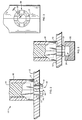
- the sterilization tray element generally indicated at 10 may be any of the components of a sterilization system well known in the prior art. It can be a cover, bottom or separate shelf in the tray. A portion of this element 12 has a number of vent holes 13 for passage of sterilization fluids, as is well known in the art.
- Resilient clamp members, of any type well known in the art and which can take many shapes, are illustrated schematically at 14 as being carried by a support 16. From the bottom of the support 16 are downwardly extending elongated fingers 17 which terminate in enlarged heads 18.
- Each enlarged head 18 has a conical end 19 and flat shoulder 20.
- the finger 17 is relatively thin and terminates in the shoulder 20.
- This shoulder is the back side of the external head 18.
- the shoulder 20 extends outwardly from the exterior portion of the finger 17.
- the fingers 17 are arcuate sections separated by spaces 26, thus providing necessary resilience to the fingers 17.
- each finger is moved radially by the conical surface 19 towards the axis of the hole so that each head 18 passes through the hole 13.
- the resilience of the finger 17 snaps the head outwardly and the shoulder 20 engages the backside of the portion of the tray element 12.
- the arrangement of the fingers 17 and their enlarged heads 18 and shoulders 20 firmly secures the support 16 with respect to the portion of the tray element 12 so that it is essentially impossible to accidentally remove support 16 from the tray, despite rough handling, dropping, etc.
- the clamping member 14 is made of a resilient sterilizable material such as a synthetic rubber, as is well known in the medical art.
- the support element 16 is preferably molded from high impact strength semi-rigid medical grade, polymeric material or the like.
- the two sets of four fingers 17 are integrally molded into the support elements 16 as shown in Figs 4A, 4B and 4C and are small arcs of a cylinder having about the same external diameter as hole 13.
- clamping member 14 is molded to shape and then positioned between two halves of the support element 16 and the whole assembly is affixed together, e.g. by means of ultrasonic welding. Alternatively, the assembly may be affixed together by adhesive means or by mechanical fastening means.
- a removal tool 22 is pressed against the head 18 of the fingers 17.
- This removal tool is shown in position in Fig. 5.
- Tool 22 preferrably has an opening 24 slightly smaller than the size of the hole 13 in which the elongated fingers are locked.
- the opening 24 is slightly smaller than the hole 13 it will compress the ends of the elongated fingers towards each other so that they have a compressed size smaller than hole 13.
- the fingers 17 can be planar rather than arcuate and the heads 18 can be triangular rather than conical. This latter arrangement would be preferable where the hole 13 is rectangular rather than circular. In this case the opening 24 in the tool 22 would be a slot slightly narrower than hole 13.
Landscapes
- Health & Medical Sciences (AREA)
- Epidemiology (AREA)
- Life Sciences & Earth Sciences (AREA)
- Animal Behavior & Ethology (AREA)
- General Health & Medical Sciences (AREA)
- Public Health (AREA)
- Veterinary Medicine (AREA)
- Apparatus For Disinfection Or Sterilisation (AREA)
Description
It is thus an object of the present invention to overcome the aforesaid and other disadvantages of the prior art. In the present invention the elements for clasping the surgical instruments are formed of resilient deformable members, as is well known in the art. These deformable members are secured within relatively rigid, strong, plastic support elements. These relatively rigid support elements have integrally formed fastening means which extend downwardly from the bottom surface of the support elements and have a size and shape designed to penetrate selected vent holes in the cover, base or support structure forming a part of the sterilization tray system. These fastening means lock the relatively rigid support element in a desired location. In addition, the fastening means are designed so that they can be readily removed by a simple tool which engages the ends of the fastening means and pushes them back through the holes in which they were previously securely locked in position.
Claims (6)
- A combination including a sterilization tray assembly for sterilizing surgical instruments, said assembly including a structure having a plurality of holes (13) and a resiliently deformable member (14) for clasping surgical instruments, a relatively rigid plastic support element (16) connected to said deformable member and being for predeterminedly positioning said resiliently deformable member with respect to different holes in said structure, said relatively rigid support element (16) having integrally formed fastening means including fingers (17) having respective tapered heads (18) and downwardly extending from a bottom surface of said support element and positioned to penetrate predetermined holes (13) of said structure to lock said support element in position, wherein the combination includes a removal tool (22) for releasing said fingers (17) from predetermined holes (13) into which said fingers have penetrated, said tool including an opening (24) adapted and operatively positioned to engage the tapered head (18) on each said finger (17) when said fingers penetrate said predetermined holes whereby to deform said fingers to release said fingers from said predetermined holes, said opening (24) being slightly smaller than said hole (13).
- The combination of claim 1, characterized in that each of said heads comprises a conical surface (19) for being engaged by said tool.
- The combination of claim 1, characterized in that said fastening means comprises at least two fingers (17) having partial conical surfaces (19), and the holes (13) in the structure (12) and the opening (24) of the tool (22) are both circular.
- The combination of claim 1, characterized in that said fingers (17) also include shoulders (20) for extending out of said predetermined holes (13) and engaging said structure (12) when said fingers penetrate said holes.
- The combination of claim 1, characterized in that the heads (18) of said fingers (17) each comprise a conical surface (19) for being engaged by said tool (22) and a shoulder (20) for engaging said structure (12) when said fingers (17) penetrate said predetermined holes (13).
- The combination of claim 1, characterized in that each of said heads (18) comprises a plurality of shoulders (20) for engaging said structure when said fingers (17) penetrate said predetermined holes (13), said shoulders (20) being separated by spaces (26) for permitting said heads to collapse to a size smaller than said predetermined holes (13) when said tool (22) engages said heads whereby to disengage said shoulders (20) from said structure (12).
Applications Claiming Priority (3)
| Application Number | Priority Date | Filing Date | Title |
|---|---|---|---|
| US43860495A | 1995-05-10 | 1995-05-10 | |
| US438604 | 1995-05-10 | ||
| PCT/US1996/006595 WO1996035460A1 (en) | 1995-05-10 | 1996-05-09 | Sterilization support and storage container system |
Publications (3)
| Publication Number | Publication Date |
|---|---|
| EP0824364A1 EP0824364A1 (en) | 1998-02-25 |
| EP0824364A4 EP0824364A4 (en) | 2000-07-19 |
| EP0824364B1 true EP0824364B1 (en) | 2002-07-31 |
Family
ID=23741294
Family Applications (1)
| Application Number | Title | Priority Date | Filing Date |
|---|---|---|---|
| EP96913973A Revoked EP0824364B1 (en) | 1995-05-10 | 1996-05-09 | Sterilization support and storage container system |
Country Status (5)
| Country | Link |
|---|---|
| US (1) | US5599512A (en) |
| EP (1) | EP0824364B1 (en) |
| DE (1) | DE69622705T2 (en) |
| ES (1) | ES2180768T3 (en) |
| WO (1) | WO1996035460A1 (en) |
Cited By (1)
| Publication number | Priority date | Publication date | Assignee | Title |
|---|---|---|---|---|
| DE102007021118A1 (en) | 2007-05-03 | 2008-11-06 | Pioneer Medical Devices Gmbh | Transportable storage device for inserting medicine products to prevent drying of substances and for conveying preparation process, and is used as catheter system, has steam-saturated atmosphere, which prevails within storage device |
Families Citing this family (34)
| Publication number | Priority date | Publication date | Assignee | Title |
|---|---|---|---|---|
| EP1021206A4 (en) * | 1997-04-22 | 2003-03-12 | Case Medical Inc | Instrument bracket for use with a sterilizable tray |
| US6244447B1 (en) * | 1997-04-22 | 2001-06-12 | Marcia A Frieze | Instrument bracket with resilient locking means for use with a sterilizable tray |
| US6872053B2 (en) * | 1997-05-05 | 2005-03-29 | King Of Fans | Quick install blade arms for ceiling fans |
| US6352411B1 (en) * | 1997-05-05 | 2002-03-05 | King Of Fans, Inc. | Quick install blade arms for ceiling fans |
| USD402884S (en) | 1997-11-21 | 1998-12-22 | Poly Vac, Inc. | Plastic clip |
| US6013227A (en) * | 1997-12-17 | 2000-01-11 | Johnson & Johnson Medical, Inc. | Lumen device reprocessor without occlusion |
| US5968459A (en) | 1998-02-12 | 1999-10-19 | Case Medical, Inc. | Filtered flash sterilization apparatus |
| US20030118491A1 (en) * | 1998-08-26 | 2003-06-26 | Frieze Marcia A. | Filtered gas plasma sterilization container with improved circulation |
| EP1002955A1 (en) | 1998-11-17 | 2000-05-24 | San-Chi Wu | Connecting device for connecting a fan blade to a rotor of a motor of a ceiling fan |
| US6534002B1 (en) * | 1998-12-30 | 2003-03-18 | Ethicon, Inc. | Flow of fluid through a lumen device from smaller-caliber end to larger-caliber end |
| US6250986B1 (en) | 1999-02-08 | 2001-06-26 | Soren Christian Sorensen | Building element for set of toy building blocks |
| US6331280B1 (en) | 1999-05-14 | 2001-12-18 | Poly Vac, Inc. | Medical instrument sterilization system |
| DE60125520T2 (en) * | 2000-02-23 | 2007-10-18 | Case Medical, Inc. | STERILIZATION TANK WITH FILTERED GAS PLASMA AND IMPROVED CIRCULATION |
| US6382575B1 (en) | 2000-07-28 | 2002-05-07 | Paragon Medical, Inc. | Instrument holder for use in conjunction with a mounting plate |
| US6431142B1 (en) * | 2000-10-05 | 2002-08-13 | Visteon Global Technologies, Inc. | Throttle blade having snap-fit wedge |
| JP4472217B2 (en) | 2000-10-16 | 2010-06-02 | オリンパス株式会社 | Biological tissue clip device |
| US7118413B2 (en) * | 2001-10-10 | 2006-10-10 | Quixemble, Inc. | Quick assembling electrical connection box apparatus and method |
| AT411785B (en) * | 2003-02-05 | 2004-05-25 | Guenter Sikora | DETACHABLE SNAP CONNECTION |
| US7284996B2 (en) * | 2005-01-11 | 2007-10-23 | Cheetah Usa Corp. | Wide safety strap for electrical fixtures |
| US7722837B2 (en) * | 2005-12-12 | 2010-05-25 | Polyvac, Inc. | Medical instrument retainer assembly and method of making the retainer |
| US7960651B2 (en) * | 2006-07-18 | 2011-06-14 | Leviton Manufacturing Company, Inc. | Wiring device and cover plate snap-on assembly |
| DE102006036460B4 (en) * | 2006-08-04 | 2015-04-09 | Aesculap Ag | strainer |
| US20080308510A1 (en) * | 2006-12-28 | 2008-12-18 | Richardson Margaret A | Dishwasher tine, tine extender and rack |
| DE102007030863A1 (en) * | 2007-06-25 | 2009-01-02 | Aesculap Ag | Surgical holder for a surgical container and surgical container |
| GB0721325D0 (en) * | 2007-10-31 | 2007-12-12 | Rolls Royce Plc | fastener arrangements |
| US20110236156A1 (en) | 2010-03-25 | 2011-09-29 | Robert Rottinghaus | Retaining pin with self biasing keeping means |
| US8827088B1 (en) | 2010-11-19 | 2014-09-09 | Greatbatch Ltd. | Wedge-lock bracket fixation |
| JP5794675B2 (en) * | 2011-06-01 | 2015-10-14 | キヤノン株式会社 | Display board mounting structure, pan head device and camera device |
| US9314542B2 (en) * | 2012-01-31 | 2016-04-19 | Phillip Bohnhoff | Method for sterilizing surgical batteries |
| US9636429B2 (en) | 2013-11-12 | 2017-05-02 | Symmetry Medical Manufacturing, Inc. | Tray and bracket system and related methods |
| US9591923B2 (en) * | 2013-12-16 | 2017-03-14 | Daniel Zeidner | Divider for shelfing and method and system for dividing a shelf |
| US20160053797A1 (en) * | 2014-08-20 | 2016-02-25 | Emerson Network Power, Energy Systems, North America, Inc. | Assemblies and methods for coupling components having slots and/or deformable stakes |
| US10391190B1 (en) | 2018-02-21 | 2019-08-27 | K1 Medical Technologies, LLC | Modular tray and bracket assembly for equipment sterilization |
| EP3814241A4 (en) * | 2018-05-08 | 2022-01-19 | Liew, Yat Fang | DIVIDERS AND DIVIDERS PLATE |
Family Cites Families (13)
| Publication number | Priority date | Publication date | Assignee | Title |
|---|---|---|---|---|
| US3908235A (en) * | 1974-12-02 | 1975-09-30 | Gregory Alan Telliard | Removable snap fastener |
| US4135868A (en) * | 1977-04-05 | 1979-01-23 | Herbert Schainholz | Supports for instrument sterilization |
| US4551110A (en) * | 1984-05-24 | 1985-11-05 | Cpg Products Corp. | Rotatable cam for use in a toy construction set |
| DE3710016A1 (en) * | 1987-03-26 | 1988-11-03 | Wolf Hans Joachim | RECEIVING ELEMENT, ESPECIALLY FOR MEDICAL TECHNOLOGY |
| US4798292A (en) * | 1987-04-03 | 1989-01-17 | Biomedical Laser Industries | Sterilization, storage, and presentation container for surgical instruments |
| US4973212A (en) * | 1989-04-06 | 1990-11-27 | Applied Power Inc. | Snap-in fastener |
| US4953269A (en) * | 1989-07-07 | 1990-09-04 | Cover-Pools, Inc. | Swimming pool anchor and removal tool |
| US5184377A (en) * | 1989-07-07 | 1993-02-09 | Cover-Pools, Inc. | Swimming pool anchor and removal tool |
| US5098676B2 (en) * | 1991-01-04 | 1997-11-25 | Poly Vac Inc | Sterilization and storage container tray |
| US5143500A (en) * | 1991-02-28 | 1992-09-01 | Itw Plastiglide | Snap engaging fastener system for providing rotary motion |
| US5384103A (en) * | 1992-03-17 | 1995-01-24 | Micromedics, Inc. | Instrument tray |
| US5346075A (en) * | 1992-04-17 | 1994-09-13 | Johnson & Johnson Medical, Inc. | Apparatus and method for holding a medical instrument |
| US5381896A (en) * | 1993-10-06 | 1995-01-17 | Ethicon, Inc. | Presentation tray for surgical instruments |
-
1996
- 1996-04-19 US US08/635,287 patent/US5599512A/en not_active Expired - Lifetime
- 1996-05-09 ES ES96913973T patent/ES2180768T3/en not_active Expired - Lifetime
- 1996-05-09 DE DE69622705T patent/DE69622705T2/en not_active Revoked
- 1996-05-09 WO PCT/US1996/006595 patent/WO1996035460A1/en not_active Ceased
- 1996-05-09 EP EP96913973A patent/EP0824364B1/en not_active Revoked
Cited By (1)
| Publication number | Priority date | Publication date | Assignee | Title |
|---|---|---|---|---|
| DE102007021118A1 (en) | 2007-05-03 | 2008-11-06 | Pioneer Medical Devices Gmbh | Transportable storage device for inserting medicine products to prevent drying of substances and for conveying preparation process, and is used as catheter system, has steam-saturated atmosphere, which prevails within storage device |
Also Published As
| Publication number | Publication date |
|---|---|
| US5599512A (en) | 1997-02-04 |
| ES2180768T3 (en) | 2003-02-16 |
| DE69622705T2 (en) | 2003-04-03 |
| EP0824364A4 (en) | 2000-07-19 |
| WO1996035460A1 (en) | 1996-11-14 |
| EP0824364A1 (en) | 1998-02-25 |
| DE69622705D1 (en) | 2002-09-05 |
Similar Documents
| Publication | Publication Date | Title |
|---|---|---|
| US5599512A (en) | Sterilization support and storage container system | |
| US6331280B1 (en) | Medical instrument sterilization system | |
| US7861860B2 (en) | Modular container for the storage, organization, protection, sterilization and delivery of medical instruments and implants | |
| US8267246B2 (en) | Mounting plate to hold medical instruments and implants using posts with flexible holders | |
| US7717264B2 (en) | Modular container for medical instruments and implants with extruded flexible bracket and rigid holders | |
| US5848714A (en) | Suture rack | |
| US6244447B1 (en) | Instrument bracket with resilient locking means for use with a sterilizable tray | |
| US5316247A (en) | Wire-and-tube-retaining pole clip | |
| US7857129B2 (en) | Container and carrier system for surgical auxiliary material | |
| CA1325187C (en) | Disposable dental tray | |
| JPS60502191A (en) | Retainer member assembly for surgical fasteners | |
| US6669157B1 (en) | Box holder device | |
| EP2759277B1 (en) | Medical device tray and method of forming the medical device tray | |
| WO1996022113A1 (en) | Sterilization and storage container tray for surgical instruments | |
| US20110288596A1 (en) | Support and Mounting for Surgical Objects | |
| GB2165218A (en) | Container for holding articles | |
| AU699721B2 (en) | Toothpicks and toothpick frame | |
| US6719562B1 (en) | Jaw model | |
| USD339424S (en) | Surgical instrument sterilization tray | |
| US20040222175A1 (en) | Surgical instrument support | |
| US5004418A (en) | Dental instrument mat | |
| EP1053755A2 (en) | Medical instrument sterilization system | |
| EP3042626B1 (en) | Medical device tray and method of forming the medical device tray | |
| US6188032B1 (en) | Stacking, self-cleaning CD holder | |
| US20080261173A1 (en) | Identification ring having an associated retaining clip, cover and stand |
Legal Events
| Date | Code | Title | Description |
|---|---|---|---|
| PUAI | Public reference made under article 153(3) epc to a published international application that has entered the european phase |
Free format text: ORIGINAL CODE: 0009012 |
|
| 17P | Request for examination filed |
Effective date: 19971029 |
|
| AK | Designated contracting states |
Kind code of ref document: A1 Designated state(s): BE DE ES FR GB |
|
| A4 | Supplementary search report drawn up and despatched |
Effective date: 20000605 |
|
| AK | Designated contracting states |
Kind code of ref document: A4 Designated state(s): BE DE ES FR GB |
|
| 17Q | First examination report despatched |
Effective date: 20010212 |
|
| GRAG | Despatch of communication of intention to grant |
Free format text: ORIGINAL CODE: EPIDOS AGRA |
|
| GRAG | Despatch of communication of intention to grant |
Free format text: ORIGINAL CODE: EPIDOS AGRA |
|
| GRAH | Despatch of communication of intention to grant a patent |
Free format text: ORIGINAL CODE: EPIDOS IGRA |
|
| GRAH | Despatch of communication of intention to grant a patent |
Free format text: ORIGINAL CODE: EPIDOS IGRA |
|
| GRAA | (expected) grant |
Free format text: ORIGINAL CODE: 0009210 |
|
| AK | Designated contracting states |
Kind code of ref document: B1 Designated state(s): BE DE ES FR GB |
|
| REG | Reference to a national code |
Ref country code: GB Ref legal event code: FG4D |
|
| REF | Corresponds to: |
Ref document number: 69622705 Country of ref document: DE Date of ref document: 20020905 |
|
| ET | Fr: translation filed | ||
| REG | Reference to a national code |
Ref country code: ES Ref legal event code: FG2A Ref document number: 2180768 Country of ref document: ES Kind code of ref document: T3 |
|
| PGFP | Annual fee paid to national office [announced via postgrant information from national office to epo] |
Ref country code: ES Payment date: 20030428 Year of fee payment: 8 |
|
| PGFP | Annual fee paid to national office [announced via postgrant information from national office to epo] |
Ref country code: GB Payment date: 20030507 Year of fee payment: 8 |
|
| PLBQ | Unpublished change to opponent data |
Free format text: ORIGINAL CODE: EPIDOS OPPO |
|
| PLBI | Opposition filed |
Free format text: ORIGINAL CODE: 0009260 |
|
| PGFP | Annual fee paid to national office [announced via postgrant information from national office to epo] |
Ref country code: DE Payment date: 20030523 Year of fee payment: 8 |
|
| PGFP | Annual fee paid to national office [announced via postgrant information from national office to epo] |
Ref country code: FR Payment date: 20030527 Year of fee payment: 8 |
|
| PLBF | Reply of patent proprietor to notice(s) of opposition |
Free format text: ORIGINAL CODE: EPIDOS OBSO |
|
| 26 | Opposition filed |
Opponent name: RICHARD WOLF GMBH Effective date: 20030428 |
|
| PGFP | Annual fee paid to national office [announced via postgrant information from national office to epo] |
Ref country code: BE Payment date: 20030716 Year of fee payment: 8 |
|
| PLAX | Notice of opposition and request to file observation + time limit sent |
Free format text: ORIGINAL CODE: EPIDOSNOBS2 |
|
| RDAF | Communication despatched that patent is revoked |
Free format text: ORIGINAL CODE: EPIDOSNREV1 |
|
| RDAG | Patent revoked |
Free format text: ORIGINAL CODE: 0009271 |
|
| STAA | Information on the status of an ep patent application or granted ep patent |
Free format text: STATUS: PATENT REVOKED |
|
| 27W | Patent revoked |
Effective date: 20040718 |
|
| GBPR | Gb: patent revoked under art. 102 of the ep convention designating the uk as contracting state |
Free format text: 20040718 |