EP0823817A2 - Magnetic recording and reproducing method, and magnetic recording and reproducing apparatus - Google Patents
Magnetic recording and reproducing method, and magnetic recording and reproducing apparatus Download PDFInfo
- Publication number
- EP0823817A2 EP0823817A2 EP97113563A EP97113563A EP0823817A2 EP 0823817 A2 EP0823817 A2 EP 0823817A2 EP 97113563 A EP97113563 A EP 97113563A EP 97113563 A EP97113563 A EP 97113563A EP 0823817 A2 EP0823817 A2 EP 0823817A2
- Authority
- EP
- European Patent Office
- Prior art keywords
- audio
- frame
- video
- signal
- outputted
- Prior art date
- Legal status (The legal status is an assumption and is not a legal conclusion. Google has not performed a legal analysis and makes no representation as to the accuracy of the status listed.)
- Granted
Links
Images


Classifications
-
- G—PHYSICS
- G11—INFORMATION STORAGE
- G11B—INFORMATION STORAGE BASED ON RELATIVE MOVEMENT BETWEEN RECORD CARRIER AND TRANSDUCER
- G11B15/00—Driving, starting or stopping record carriers of filamentary or web form; Driving both such record carriers and heads; Guiding such record carriers or containers therefor; Control thereof; Control of operating function
- G11B15/18—Driving; Starting; Stopping; Arrangements for control or regulation thereof
- G11B15/1808—Driving of both record carrier and head
- G11B15/1875—Driving of both record carrier and head adaptations for special effects or editing
-
- G—PHYSICS
- G11—INFORMATION STORAGE
- G11B—INFORMATION STORAGE BASED ON RELATIVE MOVEMENT BETWEEN RECORD CARRIER AND TRANSDUCER
- G11B27/00—Editing; Indexing; Addressing; Timing or synchronising; Monitoring; Measuring tape travel
- G11B27/005—Reproducing at a different information rate from the information rate of recording
-
- G—PHYSICS
- G11—INFORMATION STORAGE
- G11B—INFORMATION STORAGE BASED ON RELATIVE MOVEMENT BETWEEN RECORD CARRIER AND TRANSDUCER
- G11B27/00—Editing; Indexing; Addressing; Timing or synchronising; Monitoring; Measuring tape travel
- G11B27/02—Editing, e.g. varying the order of information signals recorded on, or reproduced from, record carriers
- G11B27/031—Electronic editing of digitised analogue information signals, e.g. audio or video signals
- G11B27/032—Electronic editing of digitised analogue information signals, e.g. audio or video signals on tapes
-
- G—PHYSICS
- G11—INFORMATION STORAGE
- G11B—INFORMATION STORAGE BASED ON RELATIVE MOVEMENT BETWEEN RECORD CARRIER AND TRANSDUCER
- G11B27/00—Editing; Indexing; Addressing; Timing or synchronising; Monitoring; Measuring tape travel
- G11B27/36—Monitoring, i.e. supervising the progress of recording or reproducing
-
- H—ELECTRICITY
- H04—ELECTRIC COMMUNICATION TECHNIQUE
- H04N—PICTORIAL COMMUNICATION, e.g. TELEVISION
- H04N5/00—Details of television systems
- H04N5/76—Television signal recording
- H04N5/91—Television signal processing therefor
- H04N5/92—Transformation of the television signal for recording, e.g. modulation, frequency changing; Inverse transformation for playback
- H04N5/926—Transformation of the television signal for recording, e.g. modulation, frequency changing; Inverse transformation for playback by pulse code modulation
- H04N5/9261—Transformation of the television signal for recording, e.g. modulation, frequency changing; Inverse transformation for playback by pulse code modulation involving data reduction
- H04N5/9262—Transformation of the television signal for recording, e.g. modulation, frequency changing; Inverse transformation for playback by pulse code modulation involving data reduction using predictive coding
-
- G—PHYSICS
- G11—INFORMATION STORAGE
- G11B—INFORMATION STORAGE BASED ON RELATIVE MOVEMENT BETWEEN RECORD CARRIER AND TRANSDUCER
- G11B15/00—Driving, starting or stopping record carriers of filamentary or web form; Driving both such record carriers and heads; Guiding such record carriers or containers therefor; Control thereof; Control of operating function
- G11B15/18—Driving; Starting; Stopping; Arrangements for control or regulation thereof
- G11B15/46—Controlling, regulating, or indicating speed
- G11B15/467—Controlling, regulating, or indicating speed in arrangements for recording or reproducing wherein both record carriers and heads are driven
- G11B15/4673—Controlling, regulating, or indicating speed in arrangements for recording or reproducing wherein both record carriers and heads are driven by controlling the speed of the tape while the head is rotating
-
- G—PHYSICS
- G11—INFORMATION STORAGE
- G11B—INFORMATION STORAGE BASED ON RELATIVE MOVEMENT BETWEEN RECORD CARRIER AND TRANSDUCER
- G11B2220/00—Record carriers by type
- G11B2220/90—Tape-like record carriers
-
- G—PHYSICS
- G11—INFORMATION STORAGE
- G11B—INFORMATION STORAGE BASED ON RELATIVE MOVEMENT BETWEEN RECORD CARRIER AND TRANSDUCER
- G11B5/00—Recording by magnetisation or demagnetisation of a record carrier; Reproducing by magnetic means; Record carriers therefor
- G11B5/008—Recording on, or reproducing or erasing from, magnetic tapes, sheets, e.g. cards, or wires
- G11B5/00813—Recording on, or reproducing or erasing from, magnetic tapes, sheets, e.g. cards, or wires magnetic tapes
- G11B5/00847—Recording on, or reproducing or erasing from, magnetic tapes, sheets, e.g. cards, or wires magnetic tapes on transverse tracks
- G11B5/0086—Recording on, or reproducing or erasing from, magnetic tapes, sheets, e.g. cards, or wires magnetic tapes on transverse tracks using cyclically driven heads providing segmented tracks
-
- H—ELECTRICITY
- H04—ELECTRIC COMMUNICATION TECHNIQUE
- H04N—PICTORIAL COMMUNICATION, e.g. TELEVISION
- H04N5/00—Details of television systems
- H04N5/76—Television signal recording
- H04N5/78—Television signal recording using magnetic recording
- H04N5/782—Television signal recording using magnetic recording on tape
- H04N5/783—Adaptations for reproducing at a rate different from the recording rate
-
- H—ELECTRICITY
- H04—ELECTRIC COMMUNICATION TECHNIQUE
- H04N—PICTORIAL COMMUNICATION, e.g. TELEVISION
- H04N5/00—Details of television systems
- H04N5/76—Television signal recording
- H04N5/91—Television signal processing therefor
- H04N5/93—Regeneration of the television signal or of selected parts thereof
- H04N5/94—Signal drop-out compensation
- H04N5/945—Signal drop-out compensation for signals recorded by pulse code modulation
Definitions
- the present invention relates to a magnetic recording and reproducing method for slow-motion reproduction of video and audio signals recorded on a video tape of, for example, a DV (digital video) format and a magnetic recording and reproducing apparatus capable of slow-motion reproduction of the video and audio signals, said magnetic recording and reproducing apparatus being frequently incorporated in a laptop editor or installed as a part of studio editing equipment.
- a magnetic recording and reproducing method for slow-motion reproduction of video and audio signals recorded on a video tape of, for example, a DV (digital video) format and a magnetic recording and reproducing apparatus capable of slow-motion reproduction of the video and audio signals
- said magnetic recording and reproducing apparatus being frequently incorporated in a laptop editor or installed as a part of studio editing equipment.
- FIGs. 4(a) and 4(b) show block diagrams of a conventional magnetic recording and reproducing apparatus.
- FIG. 4(a) is a block diagram of a recording system.
- FIG. 4(b) is a block diagram of a reproducing system.
- an A/D (analog-to-digital) converter 11 has a function to convert an analog video input from a television camera or other video tape recorders into a digital signal.
- a data shuffling circuit 12 has a function to selectively capture the output data from the A/D converter 11 and a digital video data input from a digital video tape recorder or a digital camera to perform data shuffling.
- a data compressing circuit 13 has a function to compress the output data of the data shuffling circuit 12 through two-dimensional discrete cosine transformation.
- An A/D converter 14 has a function to convert an analog audio input from a microphone amplifier or other video tape recorders into a digital signal.
- a sampling frequency converting circuit 15 has a function to selectively capture the output data from the A/D converter 14 and a digital audio data input from a digital video tape recorder or other digital sound sources to perform sampling frequency conversion.
- An error correcting code adding circuit 16 has a function to add an error correcting code to the output of the data compressing circuit 13 and the output of the sampling frequency converting circuit 15.
- a variable length coding circuit 17 has a function to code the output of the error correcting code adding circuit 16. The output of the variable length coding circuit 17 is sent to a magnetic head (not shown), so that the video and audio signals are recorded on a magnetic tape in frame units, for example, in the DV format.
- a detecting circuit 21 has a function to detect a signal outputted from the magnetic head (not shown) sliding over the magnetic tape.
- An error correcting circuit 22 has a function to perform error correction on the digital signal outputted from the detecting circuit 21.
- a decoding circuit 23 has a function to decode the video data included in the digital signal outputted from the error correcting circuit 22.
- a data deshuffling circuit 24 has a function to deshuffle the data outputted from the decoding circuit 23. The data deshuffling circuit 24 outputs digital video data which are used for digital dubbing.
- a D/A (digital-to-analog) converter 25 has a function to convert the output data of the data deshuffling circuit 24 into an analog signal.
- the analog video output is sent to a video monitor or used for analog dubbing.
- a frame control signal in slow-motion reproduction is added to control the error correcting operation in slow-motion reproduction.
- a sampling frequency converting circuit 26 has a function to perform sampling frequency conversion on the audio data included in the digital signal outputted from the error correcting circuit 22.
- the sampling frequency converting circuit 26 outputs digital audio data which are used for digital dubbing.
- a D/A converter 27 has a function to convert the output data of the sampling frequency converting circuit 25 into an analog signal.
- the analog audio output is sent to an audio monitor or used for analog dubbing.
- the video signal is delayed by a total of two frames: one frame in the data shuffling operation and one frame in the error correcting code adding operation, whereas the audio signal is delayed only by one frame in the error correcting code adding operation.
- a means for delaying the audio signal by one frame is provided in order to synchronize the recording timing of the video and audio signals.
- the video signal is delayed by a total of two frames: one frame in the data deshuffling operation and one frame in the error correcting operation, whereas the audio signal is delayed only by one frame.
- a means for delaying the audio signal by one frame is provided in order to synchronize the reproduction timing of the video and audio signals.
- the signal processing is performed in frame units.
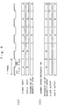
- FIG. 5 shows the timing in the recording and reproduction of the video and audio signals.
- FIG. 5(a) shows the timing in recording.
- FIG. 5(b) shows the timing in normal reproduction (normal-speed reproduction).
- Reference characters A, B, C, D and E in the figures represent frames.
- FIG. 5(a) shows that when the video input and the audio input are added in synchronism with each other to the frames A, B, C, ..., the recording by the magnetic head is performed on the frames A, B, C, ... with a delay of two frames from the video and audio inputs.
- FIG. 5(b) shows that when the reproduction by the magnetic head is performed on the frames A, B, C, ..., the video output and the audio output are performed on the frames A, B, C, ... with a delay of two frames from the reproduction by the magnetic head.
- the magnetic recording and reproducing apparatus is capable of a 1/n-speed slow-motion reproduction in which the average transport speed of the magnetic tape is 1/n that of the normal reproduction.
- n is an integer not less than 2 but not more than approximately 30.
- a slow-motion reproduction at a speed 1/n the normal reproduction speed is performed by reproducing video and audio signals recorded on a magnetic tape in a digital format such as the DV format at a speed 1/n that of the normal reproduction and repetitively outputting a video signal of the same frame over n frame periods.
- the repetitive output of a video signal of the same frame over n frame periods is realized by storing one frame of the data obtained by the error correcting circuit 22 in an error correction interpolating memory 29 and outputting the one frame of the data stored in the error correction interpolating memory 29 n times.
- the data in the error correction interpolating memory 29 are updated.
- the frame control in the slow-motion reproduction is performed based on a control signal (speed information) for sending the same signal n times.
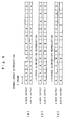
- FIG. 6 there is shown a difference in video and audio signals between the normal-speed reproduction and a 1/3-speed reproduction.
- FIG. 6(a) shows the manner of the video output and the audio output in the normal-speed reproduction and indicates that the frames of the video and audio outputs are changed to A, B, C, ... every frame period.
- FIG. 6(b) shows the manner of the video output and the audio output in the 1/3-speed reproduction and indicates that the frames of the video and audio outputs are changed to A, A, A, B, B, B, C, C, C, ... every frame period, i.e. video and audio outputs of the same frame are repetitively outputted over three consecutive frame periods.
- the above-described conventional magnetic recording and reproducing apparatus is capable of the 1/n-speed slow-motion reproduction in which the value of n is variable within a predetermined range, for example, for the purpose of editing, and in the 1/n-speed slow-motion reproduction, the audio is outputted together with the video.
- the reason why the audio as well as the video is outputted is that it is insufficient to perform editing only with reference to the video but it is necessary to perform editing with reference to the audio.
- editing video and audio signals representative of a reporter making a comment it is necessary to accurately determine the start timing of the audio generated by the reporter while monitoring the video. This is because editing performed only with reference to the video can result in a trouble such that the beginning of the audio is missing.
- An audio signal processing method has already been proposed which solves the above-mentioned problem that outputting audio signals as they are in the slow-motion reproduction makes the recognition of the audio difficult.
- the method for example, when a 1/3-speed slow-motion reproduction is performed, one frame of video signals are outputted three times, whereas for the audio signals, the time axis is tripled and one frame of audio signals are outputted once during three frame periods to synchronize the audio to the video reproduced in slow motion at a speed 1/3 the normal speed.
- a slow-motion reproduction in the reverse direction is performed, with the time axis being tripled and reversed, the audio is synchronized to the video reproduced in slow motion.
- the waveform is substantially similar to that of the audio signal in the normal reproduction, so that the audio is easily recognized. Consequently, the editing with reference to the audio is facilitated.
- Another possible method is to record the audio on a cue track in an analog format and perform editing while reproducing the audio on the cue track.
- this method to synchronize the audio to the reproduced video signal recorded in a digital format, for example, it is necessary to provide an analog delay element for delaying the audio by the time corresponding to one frame.
- an analog delay element for delaying the audio by the time corresponding to one frame.
- the number of analog delay elements is great and the cost increases accordingly.
- an object of the present invention is to provide a magnetic recording and reproducing method and a magnetic recording and reproducing apparatus facilitating editing with reference to the audio and enabling the editing to be performed with high accuracy.
- Another object of the present invention is to provide a magnetic recording and reproducing method and a magnetic recording and reproducing apparatus capable of reducing the cost for facilitating the editing with reference to the audio.
- a magnetic recording and reproducing method of the present invention in performing a slow-motion reproduction by reproducing video and audio signals recorded on a magnetic tape in a digital format at a speed lower than a speed of a normal reproduction and repetitively outputting a video signal of the same frame or field over a plurality of frame or field periods, the audio signal is outputted only during a part of the plurality of frame or field periods over which a video signal of the same frame or field is repetitively outputted, and during the remaining part of the frame or field periods, the output of the audio signal is stopped.
- the audio signal be outputted only during one frame or field period immediately after the video signal varies.
- the speed of the slow-motion reproduction ranges from 1/2 to 1/30 the speed of the normal reproduction.
- the recognition of the audio is facilitated in the slow-motion reproduction and since there is no time lag between the video and the audio, non-synchronism is not caused between the video and the audio.
- editing is performed in accordance with a time code at a splice of the video which time code is read based on the timing of the audio while the editor is listening to the audio, since editing is performed with the video and the audio being in synchronism with each other, editing is accurately performed.
- a magnetic recording and reproducing apparatus of the present invention is capable of performing a slow-motion reproduction by reproducing video and audio signals recorded on a magnetic tape in a digital format at a speed lower than a speed of a normal reproduction and repetitively outputting a video signal of the same frame or field over a plurality of frame or field periods, and switching means for controlling the output of the audio signal in response to an audio switching signal outputted in accordance with a variation in the video signal is provided so that of the plurality of frame or field periods over which a video signal of the same frame or field is repetitively outputted, only during one frame or field period immediately after the video signal varies, the audio signal is outputted, and during the remaining frame or field periods, the output of the audio signal is stopped.
- the recognition of the audio is facilitated in the slow-motion reproduction and since there is no time lag between the video and the audio, non-synchronism is not caused between the video and the audio.
- editing is performed in accordance with a time code at a splice of the video which time code is read based on the timing of the audio while the editor is listening to the audio, since editing is performed with the video and the audio being in synchronism with each other, editing is accurately performed.
- the switching means for controlling the output of the audio signal in response to the audio switching signal outputted in accordance with a variation in the video signal is necessarily added for that purpose, the cost hardly increases.
- FIGs. 1(a) and 1(b) are block diagrams of a magnetic recording and reproducing apparatus according to a first embodiment of the present invention.
- FIG. 1(a) is a block diagram of a recording system.
- FIG. 1(b) is a block diagram of a reproducing system.
- the recording system shown in FIG. 1(a) is the same as that shown in FIG. 4(a).
- the reproducing system shown in FIG. 1(b) is the same as that shown in FIG. 4(b) except that a switching means 28 is added.
- this embodiment is capable of slow-motion reproduction by reproducing video and audio signals recorded on a magnetic tape in a digital format at a speed lower than that of the normal reproduction and repetitively outputting a video signal of the same frame over a plurality of frame periods.
- the switching means 28 for controlling the output of the audio signal in response to an audio switching signal outputted in accordance with a variation in the video signal is provided on the input side of the sampling frequency converting circuit 26 so that the supply of the audio data to the sampling frequency converting circuit 26 is intermittent. Consequently, of the plurality of frame periods over which a video signal of the same frame is repetitively outputted, only during one frame period immediately after the video signal varies, the audio signal is outputted, and during the remaining frame periods, the output of the audio signal is stopped.
- the audio switching signal is generated by an audio switching signal generating circuit 30.
- the audio switching signal generating circuit 30 recognizes that new one frame of signals are captured based on the output signal of the error correcting circuit 22 and determines during which frame period of the frame periods over which the video signal is outputted n times the audio signal is outputted based on the slow-motion reproduction control signal, thereby generating the audio switching signal.
- FIG. 6(c) shows the manner of the video output and the audio output in this embodiment.
- FIG. 6(c) shows the video output and the audio output in the 1/3-speed reproduction and indicates that the frame of the video output is changed to A, A, A, B, B, B, C, C, C, ... every frame period, i.e. a video signal of the same frame is repetitively outputted during three consecutive frame periods, whereas the audio signal is outputted every three frames, i.e. the frame of the audio output is changed to A, -, -, B, -, -, C, -,-, ...
- "-" represents that the audio is not outputted.
- the audio signal is outputted only during the first one frame period of the plurality of the frame periods, so that the recognition of the audio is facilitated in the slow-motion reproduction and since there is no time lag between the audio and the video, non-synchronism is not caused between the video and the audio.
- editing is performed in accordance with a time code at a splice of the video which time code is read based on the timing of the audio while the editor is listening to the audio, since editing is performed with the video and the audio being in synchronism with each other, editing is accurately performed.
- the switching means 28 for controlling the output of the audio signal in response to the audio switching signal outputted in accordance with a variation in the video signal is necessarily added for that purpose, the cost hardly increases.
- FIG. 2 shows a block diagram of a reproducing system of a magnetic recording and reproducing apparatus according to a second embodiment of the present invention.
- the recording system is the same as that of FIG. 4(a).
- the reproducing system is the same as that of FIG. 1(b) except that the switching means 28 is inserted in a different position.
- the switching means 28 having the same function as that of the first embodiment is provided on the output side of the sampling frequency converting circuit 26 and at the front of the point where the audio data are outputted to the outside.
- the switching means 28 for controlling the output of the audio signal in response to the audio switching signal outputted in accordance with a variation in the video signal is provided on the output side of the sampling frequency converting circuit 26 and at the front of the point where the audio data are outputted to the outside so that the supply of the audio data from the sampling frequency converting circuit 26 to the D/A converter 27 and the supply of the audio data to an external video tape recorder and the like are intermittent. Consequently, of the plurality of frame periods over which a video signal of the same frame is repetitively outputted, only during one frame period immediately after the video signal varies, the audio signal is outputted, and during the remaining frame periods, the output of the audio signal is stopped.
- This embodiment produces the same advantages as the first embodiment.
- FIG. 3 shows a block diagram of a reproducing system of a magnetic recording and reproducing apparatus according to a third embodiment of the present invention.
- the recording system is the same as that of FIG. 4(a).
- the reproducing system is the same as that of FIG. 1(b) except that the switching means 28 is inserted in a different position.
- the switching means 28 having the same function as that of the first embodiment is provided on the output side of the sampling frequency converting circuit 26 and at the rear of the point where the audio data are outputted to the outside.
- the switching means 28 for controlling the output of the audio signal in response to the audio switching signal outputted in accordance with a variation in the video signal is provided on the output side of the sampling frequency converting circuit 26 and at the rear of the point where the audio data are outputted to the outside so that the supply of the audio data from the sampling frequency converting circuit 26 to the D/A converter 27 is intermittent. Consequently, of the plurality of frame periods over which a video signal of the same frame is repetitively outputted, only during one frame period immediately after the video signal varies, the audio signal is outputted, and during the remaining frame periods, the output of the audio signal is stopped.
- the supply of the audio data to an external video tape recorder and the like is performed in a similar manner to that of the conventional apparatus.
- This embodiment produces the same advantages as the first embodiment.
- the audio signal is outputted only during the first one frame period of the plurality of frame periods over which a video signal of the same frame is outputted and the output of the audio signal is stopped during the remaining frame periods
- the audio may be outputted over two or more frame periods.
- the audio signal may be outputted during the second and succeeding frame periods.
- the audio signal is outputted only during the first one frame period of the plurality of frame periods over which a video signal of the same frame is outputted irrespective of the speed of the slow-motion reproduction.
- the discontinuity of the audio caused by the thinning out of the audio signal is more conspicuous than the non-synchronism caused by the time lag between the video and the audio associated with the time axis extending operation and the time axis reversing operation. Therefore, the audio may be outputted in such a manner that when the speed of the slow-motion reproduction is low, i.e.
- the audio when the value of n is high, the audio is thinned out (the audio is outputted only during one frame period and the audio is not outputted during the remaining frame periods) and when the speed of the slow-motion reproduction is high to a degree to be close to the speed of the normal reproduction, the audio produced by the time axis extending operation or the time axis reversing operation is outputted.
- the present invention may be similarly applied to a slow-motion reproduction in which a video signal of the same field is repetitively outputted over a plurality of field periods.
- a slow-motion reproduction is enabled by reproducing video and audio signals recorded on a magnetic tape in a digital format at a speed lower than that of the normal reproduction and outputting a video signal of the same frame or field over a plurality of frame or field periods.
- An audio switching signal is generated in accordance with a variation in the video signal and the output of the audio signal is controlled in response to the audio switching signal, so that of the plurality of frame or field periods over which a video signal of the same frame or field is repetitively outputted, only during one frame or field period immediately after the video signal varies, the audio signal is outputted, and during the remaining frame or field periods, the output of the audio signal is stopped.
Landscapes
- Engineering & Computer Science (AREA)
- Signal Processing (AREA)
- Multimedia (AREA)
- Television Signal Processing For Recording (AREA)
- Signal Processing For Digital Recording And Reproducing (AREA)
Abstract
Description
Claims (5)
- A magnetic recording and reproducing method for performing a slow-motion reproduction by reproducing video and audio signals recorded on a magnetic tape in a digital format at a speed lower than a speed of a normal reproduction and repetitively outputting a video signal of the same frame or field over a plurality of frame or field periods,
wherein the audio signal is outputted only during a part of the plurality of frame or field periods over which a video signal of the same frame or field is repetitively outputted, and during the remaining part of the frame or field periods, the output of the audio signal is stopped. - A magnetic recording and reproducing method according to claim 1, wherein the audio signal is outputted only during one frame or field period immediately after the video signal varies.
- A magnetic recording and reproducing method according to claim 1, wherein the speed of the slow-motion reproduction ranges from 1/2 to 1/30 the speed of the normal reproduction.
- A magnetic recording and reproducing apparatus capable of performing a slow-motion reproduction by reproducing video and audio signals recorded on a magnetic tape in a digital format at a speed lower than a speed of a normal reproduction and repetitively outputting a video signal of the same frame or field over a plurality of frame or field periods,
wherein switching means for controlling the output of the audio signal in response to an audio switching signal outputted in accordance with a variation in the video signal is provided so that of the plurality of frame or field periods over which a video signal of the same frame or field is repetitively outputted, only during one frame or field period immediately after the video signal varies, the audio signal is outputted, and during the remaining frame or field periods, the output of the audio signal is stopped. - A magnetic recording and reproducing apparatus according to claim 4, wherein the speed of the slow-motion reproduction ranges from 1/2 to 1/30 the speed of the normal reproduction.
Applications Claiming Priority (3)
| Application Number | Priority Date | Filing Date | Title |
|---|---|---|---|
| JP20975196A JP3148648B2 (en) | 1996-08-08 | 1996-08-08 | Magnetic recording / reproducing method and magnetic recording / reproducing apparatus |
| JP20975196 | 1996-08-08 | ||
| JP209751/96 | 1996-08-08 |
Publications (3)
| Publication Number | Publication Date |
|---|---|
| EP0823817A2 true EP0823817A2 (en) | 1998-02-11 |
| EP0823817A3 EP0823817A3 (en) | 1999-06-16 |
| EP0823817B1 EP0823817B1 (en) | 2005-11-09 |
Family
ID=16578039
Family Applications (1)
| Application Number | Title | Priority Date | Filing Date |
|---|---|---|---|
| EP97113563A Expired - Lifetime EP0823817B1 (en) | 1996-08-08 | 1997-08-06 | Magnetic reproducing method and magnetic reproducing apparatus |
Country Status (4)
| Country | Link |
|---|---|
| US (1) | US6434321B1 (en) |
| EP (1) | EP0823817B1 (en) |
| JP (1) | JP3148648B2 (en) |
| DE (1) | DE69734548T2 (en) |
Cited By (3)
| Publication number | Priority date | Publication date | Assignee | Title |
|---|---|---|---|---|
| EP1018835A2 (en) * | 1999-01-08 | 2000-07-12 | Pace Micro Technology PLC | Improvements relating to a video data receiver and method of displaying these data |
| EP1119194A2 (en) * | 2000-01-19 | 2001-07-25 | Pioneer Corporation | Audio and video reproduction apparatus, and audio and video reproduction method |
| EP1259072A1 (en) * | 1999-11-10 | 2002-11-20 | Matsushita Electric Industrial Co., Ltd. | Magnetic medium recording/reproducing apparatus |
Families Citing this family (9)
| Publication number | Priority date | Publication date | Assignee | Title |
|---|---|---|---|---|
| DE60108400T2 (en) * | 2000-08-10 | 2006-03-30 | Thomson Licensing S.A., Boulogne | MEMORY ADDRESSING METHOD FOR SYSTEMS WITH A DATA REPEATABILITY WITH A CHANGED SPEED |
| US20040201747A1 (en) * | 2001-05-08 | 2004-10-14 | Woods Scott A. | Slow video mode for use in a digital still camera |
| US8254766B2 (en) * | 2007-09-27 | 2012-08-28 | Intel Corporation | Method and apparatus for media playback |
| JP5682512B2 (en) * | 2011-09-02 | 2015-03-11 | 株式会社ニコン | Imaging apparatus and image / audio reproduction apparatus |
| US8971689B2 (en) | 2011-09-02 | 2015-03-03 | Nikon Corporation | Imaging device and image-audio playback device |
| WO2014092682A1 (en) | 2012-12-11 | 2014-06-19 | Avon Products, Inc. | Serissa japonica extracts and methods of use |
| US9034396B2 (en) | 2012-12-11 | 2015-05-19 | Avon Products, Inc. | Serissa japonica extracts and methods of use |
| US9186316B2 (en) | 2012-12-11 | 2015-11-17 | Avon Products, Inc. | Stephanotis jasminoides extracts and methods of use |
| US10231001B2 (en) | 2016-05-24 | 2019-03-12 | Divx, Llc | Systems and methods for providing audio content during trick-play playback |
Citations (1)
| Publication number | Priority date | Publication date | Assignee | Title |
|---|---|---|---|---|
| EP0681398A2 (en) * | 1994-04-28 | 1995-11-08 | International Business Machines Corporation | Synchronised, variable speed playback of digitally recorded audio and video |
Family Cites Families (6)
| Publication number | Priority date | Publication date | Assignee | Title |
|---|---|---|---|---|
| GB2167889B (en) * | 1984-11-28 | 1988-05-11 | Sony Corp | Video tape recorders |
| US5414568A (en) * | 1989-10-23 | 1995-05-09 | Matsushita Electric Industrial Co., Ltd. | Variable speed digital signal reproducing apparatus |
| GB9206651D0 (en) * | 1992-03-26 | 1992-05-06 | Solid State Logic Ltd | Video processing |
| JPH06338142A (en) * | 1993-05-28 | 1994-12-06 | Sony Corp | Method and apparatus for recording digital audio signal and recording medium thereof |
| JP3495102B2 (en) * | 1993-08-26 | 2004-02-09 | エルジー電子株式会社 | Apparatus and method for tracking adjustment during video tape recorder playback |
| BR9506878A (en) * | 1994-12-23 | 1997-08-19 | Philips Electronics Nv | Process for encoding error-protecting data device for protecting error-encoding digital video recorder unit storage media and digital video cassette |
-
1996
- 1996-08-08 JP JP20975196A patent/JP3148648B2/en not_active Expired - Fee Related
-
1997
- 1997-07-31 US US08/903,772 patent/US6434321B1/en not_active Expired - Fee Related
- 1997-08-06 DE DE69734548T patent/DE69734548T2/en not_active Expired - Fee Related
- 1997-08-06 EP EP97113563A patent/EP0823817B1/en not_active Expired - Lifetime
Patent Citations (1)
| Publication number | Priority date | Publication date | Assignee | Title |
|---|---|---|---|---|
| EP0681398A2 (en) * | 1994-04-28 | 1995-11-08 | International Business Machines Corporation | Synchronised, variable speed playback of digitally recorded audio and video |
Cited By (6)
| Publication number | Priority date | Publication date | Assignee | Title |
|---|---|---|---|---|
| EP1018835A2 (en) * | 1999-01-08 | 2000-07-12 | Pace Micro Technology PLC | Improvements relating to a video data receiver and method of displaying these data |
| EP1259072A1 (en) * | 1999-11-10 | 2002-11-20 | Matsushita Electric Industrial Co., Ltd. | Magnetic medium recording/reproducing apparatus |
| EP1259072A4 (en) * | 1999-11-10 | 2005-04-27 | Matsushita Electric Ind Co Ltd | Magnetic medium recording/reproducing apparatus |
| US6983098B1 (en) | 1999-11-10 | 2006-01-03 | Matsushita Electric Industrial Co., Ltd. | Magnetic medium recording and reproducing apparatus |
| EP1119194A2 (en) * | 2000-01-19 | 2001-07-25 | Pioneer Corporation | Audio and video reproduction apparatus, and audio and video reproduction method |
| EP1119194A3 (en) * | 2000-01-19 | 2005-10-12 | Pioneer Corporation | Audio and video reproduction apparatus, and audio and video reproduction method |
Also Published As
| Publication number | Publication date |
|---|---|
| JPH1056619A (en) | 1998-02-24 |
| DE69734548T2 (en) | 2006-07-20 |
| US6434321B1 (en) | 2002-08-13 |
| EP0823817B1 (en) | 2005-11-09 |
| JP3148648B2 (en) | 2001-03-19 |
| DE69734548D1 (en) | 2005-12-15 |
| EP0823817A3 (en) | 1999-06-16 |
Similar Documents
| Publication | Publication Date | Title |
|---|---|---|
| CA2071595C (en) | Method and apparatus for recording compressed audio data on a video recording medium | |
| US4477844A (en) | Apparatus for recording a digital audio signal in a track with a video signal | |
| US4963992A (en) | Apparatus for recording/reproducing digital video signals in both a standard mode and a long playing mode | |
| GB2054244A (en) | Editing digital signals | |
| US6434321B1 (en) | Method and apparatus for slow-motion video and audio reproduction | |
| US6370324B1 (en) | Digital information recorder/reproducer with ECC encoding of compressed signal and selective bypass of ECC encoding | |
| EP0214343B1 (en) | Reproducing apparatus | |
| US5438459A (en) | Method of processing and recording data while reproducing the same and apparatus for the method | |
| EP0750430B1 (en) | Recording and reproducing video data | |
| JP3287875B2 (en) | Video tape recorder | |
| JPH01264385A (en) | Video signal recording/reproducing device | |
| US5790556A (en) | Method and apparatus for video signal processing | |
| JP2685901B2 (en) | Digital signal processing equipment | |
| US6289171B1 (en) | Arrangement for recording or reproducing a digital video signal and a corresponding digital audio signal | |
| EP1128672A2 (en) | Digital VTR and video recording/reproducing apparatus | |
| JP2735289B2 (en) | Digital signal processing equipment | |
| US6766105B1 (en) | Digital VTR | |
| US5784520A (en) | Audio signal reproducing apparatus | |
| EP0548359B1 (en) | Variable-speed digital signal reproducing device | |
| JP2678063B2 (en) | Digital signal processing equipment | |
| KR100296210B1 (en) | A voice signal reproducing device | |
| JP2786481B2 (en) | Digital signal processing equipment | |
| JP3594186B2 (en) | Video tape recorder | |
| JPH0723341A (en) | Signal synchronizing device | |
| JPS6390274A (en) | Magnatic tape recording and reproducing system |
Legal Events
| Date | Code | Title | Description |
|---|---|---|---|
| PUAI | Public reference made under article 153(3) epc to a published international application that has entered the european phase |
Free format text: ORIGINAL CODE: 0009012 |
|
| AK | Designated contracting states |
Kind code of ref document: A2 Designated state(s): DE GB NL |
|
| 17P | Request for examination filed |
Effective date: 19980408 |
|
| PUAL | Search report despatched |
Free format text: ORIGINAL CODE: 0009013 |
|
| AK | Designated contracting states |
Kind code of ref document: A3 Designated state(s): AT BE CH DE DK ES FI FR GB GR IE IT LI LU MC NL PT SE |
|
| AKX | Designation fees paid |
Free format text: DE GB NL |
|
| 17Q | First examination report despatched |
Effective date: 20040127 |
|
| RTI1 | Title (correction) |
Free format text: MAGNETIC REPRODUCING METHOD AND MAGNETIC REPRODUCING APPARATUS |
|
| GRAP | Despatch of communication of intention to grant a patent |
Free format text: ORIGINAL CODE: EPIDOSNIGR1 |
|
| GRAS | Grant fee paid |
Free format text: ORIGINAL CODE: EPIDOSNIGR3 |
|
| GRAA | (expected) grant |
Free format text: ORIGINAL CODE: 0009210 |
|
| AK | Designated contracting states |
Kind code of ref document: B1 Designated state(s): DE GB NL |
|
| PG25 | Lapsed in a contracting state [announced via postgrant information from national office to epo] |
Ref country code: NL Free format text: LAPSE BECAUSE OF FAILURE TO SUBMIT A TRANSLATION OF THE DESCRIPTION OR TO PAY THE FEE WITHIN THE PRESCRIBED TIME-LIMIT Effective date: 20051109 |
|
| REG | Reference to a national code |
Ref country code: GB Ref legal event code: FG4D |
|
| REF | Corresponds to: |
Ref document number: 69734548 Country of ref document: DE Date of ref document: 20051215 Kind code of ref document: P |
|
| NLV1 | Nl: lapsed or annulled due to failure to fulfill the requirements of art. 29p and 29m of the patents act | ||
| PLBE | No opposition filed within time limit |
Free format text: ORIGINAL CODE: 0009261 |
|
| STAA | Information on the status of an ep patent application or granted ep patent |
Free format text: STATUS: NO OPPOSITION FILED WITHIN TIME LIMIT |
|
| 26N | No opposition filed |
Effective date: 20060810 |
|
| PGFP | Annual fee paid to national office [announced via postgrant information from national office to epo] |
Ref country code: DE Payment date: 20080821 Year of fee payment: 12 |
|
| PGFP | Annual fee paid to national office [announced via postgrant information from national office to epo] |
Ref country code: GB Payment date: 20080813 Year of fee payment: 12 |
|
| GBPC | Gb: european patent ceased through non-payment of renewal fee |
Effective date: 20090806 |
|
| PG25 | Lapsed in a contracting state [announced via postgrant information from national office to epo] |
Ref country code: DE Free format text: LAPSE BECAUSE OF NON-PAYMENT OF DUE FEES Effective date: 20100302 |
|
| PG25 | Lapsed in a contracting state [announced via postgrant information from national office to epo] |
Ref country code: GB Free format text: LAPSE BECAUSE OF NON-PAYMENT OF DUE FEES Effective date: 20090806 |