EP0823623B1 - Procedure for detecting tyre defects - Google Patents
Procedure for detecting tyre defects Download PDFInfo
- Publication number
- EP0823623B1 EP0823623B1 EP96112685A EP96112685A EP0823623B1 EP 0823623 B1 EP0823623 B1 EP 0823623B1 EP 96112685 A EP96112685 A EP 96112685A EP 96112685 A EP96112685 A EP 96112685A EP 0823623 B1 EP0823623 B1 EP 0823623B1
- Authority
- EP
- European Patent Office
- Prior art keywords
- tyre
- grey
- value
- image
- tire
- Prior art date
- Legal status (The legal status is an assumption and is not a legal conclusion. Google has not performed a legal analysis and makes no representation as to the accuracy of the status listed.)
- Expired - Lifetime
Links
- 238000000034 method Methods 0.000 title claims description 32
- 230000007547 defect Effects 0.000 title claims description 24
- 238000011156 evaluation Methods 0.000 claims description 20
- 238000012360 testing method Methods 0.000 claims description 15
- 230000005855 radiation Effects 0.000 claims description 10
- 238000012545 processing Methods 0.000 claims description 4
- 230000008859 change Effects 0.000 claims description 3
- 230000003287 optical effect Effects 0.000 claims description 3
- 230000001427 coherent effect Effects 0.000 claims description 2
- 238000003384 imaging method Methods 0.000 claims description 2
- 238000006073 displacement reaction Methods 0.000 claims 1
- 238000005728 strengthening Methods 0.000 claims 1
- 238000012956 testing procedure Methods 0.000 claims 1
- 238000010008 shearing Methods 0.000 description 15
- 238000009826 distribution Methods 0.000 description 14
- 238000001514 detection method Methods 0.000 description 4
- 230000000694 effects Effects 0.000 description 4
- 229910000831 Steel Inorganic materials 0.000 description 3
- 230000008569 process Effects 0.000 description 3
- 239000010959 steel Substances 0.000 description 3
- 230000007704 transition Effects 0.000 description 3
- 238000011161 development Methods 0.000 description 2
- 230000003993 interaction Effects 0.000 description 2
- 230000002787 reinforcement Effects 0.000 description 2
- 238000012935 Averaging Methods 0.000 description 1
- 230000005856 abnormality Effects 0.000 description 1
- 238000006243 chemical reaction Methods 0.000 description 1
- 238000010276 construction Methods 0.000 description 1
- 238000013461 design Methods 0.000 description 1
- 230000004069 differentiation Effects 0.000 description 1
- 238000005286 illumination Methods 0.000 description 1
- 238000010606 normalization Methods 0.000 description 1
Images


Classifications
-
- G—PHYSICS
- G01—MEASURING; TESTING
- G01M—TESTING STATIC OR DYNAMIC BALANCE OF MACHINES OR STRUCTURES; TESTING OF STRUCTURES OR APPARATUS, NOT OTHERWISE PROVIDED FOR
- G01M17/00—Testing of vehicles
- G01M17/007—Wheeled or endless-tracked vehicles
- G01M17/02—Tyres
- G01M17/027—Tyres using light, e.g. infrared, ultraviolet or holographic techniques
Definitions
- the invention relates to a method for determining Tire defects, preferably in truck tires, after Preamble of claim 1.
- a method is known from DE-OS-42 31 578 A1, at the side wall of a tire using several light-emitting diodes irradiated with coherent light and by that Tire backscattered radiation in two partial radiations is divided.
- the two partial radiations become like this reunited that the two partial radiations are slightly offset from each other (shearing).
- the the Partial radiations carrying image information become one supplied electronic image sensor system.
- the on the Radiation impinging image sensor is after a A / D conversion converted into digital signals. Before the The tire is initially tested with a predetermined one Inflated pressure.
- DE-OS-42 31 578 A1 To improve the known from DE-OS-42 31 578 A1 The process is proposed in DE 195 01 073 A1, preferably according to the method of DE-OS-42 31 578 A1 by tangential shearing in the circumferential direction of the Tire (more precisely through a shearing in one too a radial direction of the tire) and steady output grayscale image in the way to differentiate partially that a second the output gray scale image same gray value image is generated, and this against the output gray scale image in the shearing direction is geometrically shifted and manipulated in this way Second gray value image subtracted from the output gray value image so that a resulting grayscale image arises.
- Truck tires have a multi-layer steel belt package that has its own Represents reinforcement.
- the carcass provides one of the belt packs with its steel mesh insert largely independent reinforcement. There are therefore hardly any interactions between the belt package and the carcass in terms of strength.
- the highest Tensions arise in the shoulder area in the transition zone belt package and carcass. It happens there from extreme loads or damage to detach of the belt package. These replacements can hardly be done from the outside can be detected.
- the invention has for its object a method to create tires with which you can also test Belt edge detachments for truck tires and other tires, where the belt and carcass are largely independent Strengths are, reliably recorded.
- This task is accomplished by a method with the characteristics of claim 1 solved.
- the output gray-scale image becomes determined with the help of a deformation that by changing the pressure, preferably by lowering the pressure tire pressure is reached.
- a drop in pressure can the belt edge of a truck tire as Clamping point can be viewed.
- the deformations therefore correspond approximately to the deformations of a beam clamped on one side a force at a distance from the clamping point Body is applied.
- the method according to the invention is then not only for the detection of tire defects in the Shoulder area of truck tires but also for detection of defects in all areas of a tire who have a relationship of patronage, which one unilaterally clamped carrier are similar.
- the deformation can also be achieved by increasing the pressure.
- Fig. 1 shows schematically the cross section of a test Truck tire 10 with a carcass 13 containing steel mesh, a tread 11 and one between the carcass 13 and of the tread 11 arranged belt package 12.
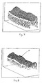
- Fig. 2 a test section which is circular with respect to the tire axis 15 of the side wall 14 of the truck tire 10 shown, the upper Edge in the area of the transition between carcass 13 and Belt package 12 is located.
- the Test area 15 initially by means of from DE-OS-42 31 578 A1 known method checked, in which several laser diodes for Illumination can be used and the shearing in radial Direction of the truck tire, i.e. 2 from top to bottom he follows.
- the deformation occurs because the tire pressure is reduced, whereby the sidewall 14 of the tire by Line Q in the transition area between carcass 13 and belt package 12 is moved inwards.
- the deformation corresponds therefore approximately the deformation of a one-sided clamped Carrier.
- a modulo-2 ⁇ image is obtained, which thus becomes an output gray-scale image is implemented that the gray values of the individual Pixels the difference in the deformation of two points on the Specify the test object on a radial or on the radial parallel straight lines are adjacent.
- Suitable development methods for this are described for example in “Digital Processing and evaluation of interference images”, Wolfgang Osten, Akademieverlag Berlin, 1991, pp. 138 to 144 and in “Proceedings of the First International Workshop on Automatic Processing of Fringe Patterns ", Akademieverlag Berlin, 1989, Pp. 23 to 31.
- a narrow circular arc-shaped strip of the output gray-scale image which is a narrow circular arc Strips 16 on the outer edge of the test area 15 of the Side wall 14 with a width S of 5 mm, for example corresponds, in the computer a mean gray value by known Methods of averaging determined. Doing so each pixel in the strip of the output gray scale image a certain gray value from a gray value range of 0 (black) and 255 (white). Then the Grayscale values of all pixels in the narrow strip added and divided the sum by the number of pixels.
- the average determined in this way is then in the computer Gray value from a predetermined reference gray value, e.g. subtracted from the gray value 128. Now the in the computer Result of the subtraction corresponding gray value, which too can be negative to the gray values of the individual pixels of the output gray-scale image is added, whereby an evaluation gray-scale image is obtained.
- FIG. 3 shows the evaluation grayscale image of a truck tire, that has no defect in the test area.
- 4 are the gray value distributions of the evaluation gray value image of Fig. 3 along two parallel to the radial Lines I and II shown. It can be clearly seen that the two gray value distributions are approximately the same Level, both gray value distributions below of a threshold gray value SW, based on which a Tire defect is determined.
- FIG. 5 shows the evaluation grayscale image of a truck tire with a tire defect F on the straight line I, for example caused by a detachment in the area of the belt edge has been.
- Fig. 6 it can be clearly seen that the gray level the gray value distribution along the straight line I clearly above the gray value level along the gray value distribution the straight line II, along which there is no tire defect is available.
- the gray value distribution I exceeds in the right area Fig. 6, i.e. the area of the tire defect the threshold gray value SW, which indicates an error.
- FIG. 7 and 8 show a three-dimensional representation of the Gray value distributions of the evaluation gray value images from FIG. 3. It can clearly be seen that the gray value distribution of Fig. 8 in the area of the tire defect F a hill-like Has increase, which indicates the tire defect F.
- a suitable threshold gray value, which is exceeded by a Tire defect indicates, for example, 180.
- the threshold depends on the test parameters, e.g. the Shearing distance, air lowering or the type of tire.
- the evaluation grayscale image when a tire defect is detected exceeds the threshold gray value, for example a signal is emitted by the computer, which is a horn signal a horn device or an optical signal optical display triggers, causing an operator to carries out the method according to the invention in a simple manner a tire defect can be indicated. After triggering the whole process can be stopped because the tested truck tires unsuitable for further processing is.
- the threshold gray value for example a signal is emitted by the computer, which is a horn signal a horn device or an optical signal optical display triggers, causing an operator to carries out the method according to the invention in a simple manner a tire defect can be indicated. After triggering the whole process can be stopped because the tested truck tires unsuitable for further processing is.
Landscapes
- Physics & Mathematics (AREA)
- General Physics & Mathematics (AREA)
- Tires In General (AREA)
- Length Measuring Devices By Optical Means (AREA)
- Image Processing (AREA)
Description
Die Erfindung betrifft ein Verfahren zur Ermittlung von Reifendefekten, vorzugsweise bei LKW-Reifen, nach dem Oberbegriff des Patentanspruchs 1.The invention relates to a method for determining Tire defects, preferably in truck tires, after Preamble of claim 1.
Aus der DE-OS-42 31 578 A1 ist ein Verfahren bekannt, bei dem die Seitenwand eines Reifens mittels mehrerer Leuchtdioden mit kohärentem Licht bestrahlt und die von dem Reifen zurückgestreute Strahlung in zwei Teilstrahlungen aufgeteilt wird. Die zwei Teilstrahlungen werden derart wieder zusammengeführt, daß die beide Teilstrahlungen zueinander leicht versetzt sind (Shearing). Die die Bildinformation tragenden Teilstrahlungen werden einem elektronischen Bildsensorsystem zugeführt. Dabei wird die Außenseite der Reifenseitenwand durch die abbildende Komponente auf dem Bildsensor abgebildet. Die auf den Bildsensor auftreffende Strahlung wird nach einer A/D-Wandlung in digitale Signale umgewandelt. Vor der Prüfung ist der Reifen zunächst mit einem vorherbestimmten Druck aufgepumpt. In diesem Zustand wird in einer ersten Bildfolge eine Teilstrahlung bezüglich der zweiten Teilstrahlung schrittweise phasenverschoben und diese Bildfolge in dem temporären Speicher eines Rechners abgelegt. Anschließend wird der Reifendruck verringert und in diesem Zustand eine zweite Bildfolge erzeugt. Die einzelnen Schritte der ersten und zweiten Bildfolge werden in einem Rechner zu einem Modulo-2π-Bild verarbeitet. Das aus diesem Verfahren resultierende Bild ist einerseits das Ergebnis der konstruktiven und geometrischen Ausgestaltung des Reifens und andererseits eine Folge von Strukturinhomogenitäten. Das bekannte Verfahren hat allerdings den Nachteil, daß der Effekt von Strukturinhomogenitäten nur dann zu erkennen ist, wenn der Effekt signifikant größer ist als die konstruktiv oder geometrisch bedingten Effekte. A method is known from DE-OS-42 31 578 A1, at the side wall of a tire using several light-emitting diodes irradiated with coherent light and by that Tire backscattered radiation in two partial radiations is divided. The two partial radiations become like this reunited that the two partial radiations are slightly offset from each other (shearing). The the Partial radiations carrying image information become one supplied electronic image sensor system. The Outside of the tire sidewall through the imaging Component shown on the image sensor. The on the Radiation impinging image sensor is after a A / D conversion converted into digital signals. Before the The tire is initially tested with a predetermined one Inflated pressure. In this state, in a partial radiation with respect to the second Partial radiation gradually shifted in phase and this Image sequence in the temporary memory of a computer stored. The tire pressure is then reduced and generates a second image sequence in this state. The individual steps of the first and second image sequence are processed in a computer to a modulo 2π image. The picture resulting from this procedure is on the one hand the result of the constructive and geometric Design of the tire and on the other hand Sequence of structural inhomogeneities. The well-known process has the disadvantage, however, that the effect of structural inhomogeneities can only be recognized if the Effect is significantly greater than that constructive or geometric effects.
Zur Verbesserung des aus der DE-OS-42 31 578 A1 bekannten Verfahrens wird in der DE 195 01 073 A1 vorgeschlagen, das gemäß dem Verfahren der DE-OS-42 31 578 A1 vorzugsweise durch Tangential-Shearing in Umfangsrichtung des Reifens (genauer gesagt durch ein Shearing in einer zu einer Radialen des Reifens senkrechten Richtung) erhaltene und verstetigte Ausgangs-Grauwertbild in der Weise partiell zu differenzieren, daß ein zweites dem Ausgangs-Grauwertbild gleiches Grauwertbild erzeugt wird, und dieses gegen das Ausgangs-Grauwertbild in Shearing-Richtung geometrisch verschoben wird und das so manipulierte Zweit-Grauwertbild von dem Ausgangs-Grauwertbild subtrahiert wird, damit ein resultierendes Grauwertbild entsteht.To improve the known from DE-OS-42 31 578 A1 The process is proposed in DE 195 01 073 A1, preferably according to the method of DE-OS-42 31 578 A1 by tangential shearing in the circumferential direction of the Tire (more precisely through a shearing in one too a radial direction of the tire) and steady output grayscale image in the way to differentiate partially that a second the output gray scale image same gray value image is generated, and this against the output gray scale image in the shearing direction is geometrically shifted and manipulated in this way Second gray value image subtracted from the output gray value image so that a resulting grayscale image arises.
Mit dieser Lösung wurde es bei der Prüfung von PKW-Reifen möglich, daß sich im resultierenden Bild Strukturinhomogenitäten von konstruktiv oder geometrisch bedingten Effekten deutlich abheben und deshalb auf einfache Weise zu identifizieren sind. Außerdem ist es möglich, die jeweilige Strukturinhomogenität einem konkaven oder konvexen Typ zuzuordnen. Das aus der DE 195 01 073.6 A1 bekannte Verfahren ist zur Erkennung von Reifendefekten bei PKW-Reifen oder ähnlichen Reifen sehr gut geeignet. Allerdings können mit diesem Verfahren Reifendefekte bei LKW-Reifen nicht mit ausreichender Sicherheit festgestellt werden. Der Grund hierfür liegt darin, daß bei einem PKW-Reifen und ähnlich aufgebauten Reifen Gürtel und Karkasse als ein einziger Festigkeitsträger angesehen werden können. Dies hat zur Folge, daß sich Festigkeitsabnormitäten unabhängig von deren Lage auf der gesamten Reifenaußenseite und somit auch in der Reifenseitenwand auswirken. LKW-Reifen weisen jedoch in der Regel einen vollkommen anderen Aufbau als PKW-Reifen auf. LKW-Reifen haben ein mehrlagiges Stahlgürtelpaket, das einen eigenständigen Festigkeitsträger darstellt. Die Karkasse stellt mit ihrer Stahlgewebeeinlage einen vom Gürtelpaket weitgehend unabhängigen Festigkeitsträger dar. Es bestehen daher zwischen Gürtelpaket und Karkasse kaum Wechselwirkungen in Bezug auf die Festigkeit. Die höchsten Spannungen entstehen im Schulterbereich in der Übergangszone von Gürtelpaket und Karkasse. Dort kommt es im Falle von extremen Belastungen oder Beschädigungen zum Ablösen des Gürtelpakets. Diese Ablösungen können von außen kaum detektiert werden.With this solution it was when testing car tires possible that there are structural inhomogeneities in the resulting image of constructive or geometrical reasons Stand out effects clearly and therefore in a simple manner are to be identified. It is also possible to respective structural inhomogeneity a concave or assign convex type. That from DE 195 01 073.6 A1 known method is for the detection of tire defects very suitable for car tires or similar tires. However, tire defects can be caused by this procedure Truck tires not found with sufficient certainty become. The reason for this is that a car tire and similarly constructed tire belt and carcass considered as a single strength member can be. As a result, there are strength abnormalities regardless of their location on the whole Tire outside and therefore also in the tire sidewall impact. However, truck tires usually have one completely different structure than car tires. Truck tires have a multi-layer steel belt package that has its own Represents reinforcement. The carcass provides one of the belt packs with its steel mesh insert largely independent reinforcement. There are therefore hardly any interactions between the belt package and the carcass in terms of strength. The highest Tensions arise in the shoulder area in the transition zone belt package and carcass. It happens there from extreme loads or damage to detach of the belt package. These replacements can hardly be done from the outside can be detected.
Was eine Gürtelkantenablösung betrifft, ist in der DE 195 01 073.6 A1 erläutert, dass diese typischerweise einen tangentialen Verlauf zeigt und daher eine beste Indikation durch radiales Shearing gegeben ist.Regarding belt edge detachment, DE 195 01 073.6 A1 explains that this is typically a shows tangential course and therefore a best indication is given by radial shearing.
Der Erfindung liegt die Aufgabe zugrunde, ein Verfahren zur Prüfung von Reifen zu schaffen, mit dem sich auch Gürtelkantenablösungen bei LKW-Reifen und anderen Reifen, bei denen Gürtel und Karkasse weitgehend unabhängige Festigkeitsträger sind, zuverlässig erfassen lassen.The invention has for its object a method to create tires with which you can also test Belt edge detachments for truck tires and other tires, where the belt and carcass are largely independent Strengths are, reliably recorded.
Diese Aufgabe wird durch ein Verfahren mit den Merkmalen des Patentanspruchs 1 gelöst.This task is accomplished by a method with the characteristics of claim 1 solved.
Vorteilhafte Ausführungsarten des erfindungsgemäßen Verfahrens sind Gegenstand der Patentansprüche 2 bis 8.Advantageous embodiments of the method according to the invention are the subject of claims 2 to 8.
Bei der Entwicklung des erfindungsgemäßen Verfahrens hat sich gezeigt, dass ein Tangential-Shearing in Umfangsrichtung des Reifens (genauer gesagt ein Shearing in einer zur einer Radialen des Reifens senkrechten Richtung) ungeeignet ist, da zwischen Gürtelpaket und Karkasse keine Wechselwirkungen bestehen. Fehler verlaufen daher im Schulterbereich in aller Regel in Umfangsrichtung. Die Fehlerausdehnung in Umfangsrichtung beträgt normalerweise ein Mehrfaches des typischen Shearingabstandes. Die Schnittkurve der Grauwertverteilung der Verformung weist in Umfangsrichtung eine kleine, in Radialrichtung jedoch eine große Steigung auf. Bei einem Tangentialshearing wird deswegen am Anfang und am Ende eines Fehlers nur ein schwaches Signal erhalten. Aus diesem Grund wird bei dem erfindungsgemäßen Verfahren ein Radial-Shearing durchgeführt, d.h. es werden Punkte überlagert, die auf einer Radialen und auf zur Radialen parallelen Geraden der Seitenwand nebeneinanderliegen.During the development of the method according to the invention it has been shown that a tangential shearing in the circumferential direction of the tire (more precisely a shearing in a direction perpendicular to a radial of the tire) is unsuitable because between the belt package and the carcass there are no interactions. Mistakes went therefore in the shoulder area usually in the circumferential direction. The extent of the error in the circumferential direction is usually a multiple of the typical shearing distance. The intersection curve of the gray value distribution of the Deformation has a small circumferential direction, in Radial direction, however, a large slope. At a Tangentialshearing is therefore at the beginning and at the end received only a weak signal of an error. Out for this reason, in the method according to the invention Radial shearing carried out, i.e. dots are overlaid, the one on the radial and on the radial parallel straight lines of the side wall lie next to each other.
Bei einem Radial-Shearing im Schulterbereich eines LKW-Reifens weist die Kurve der Grauwertverteilung bei einer Verformungsänderung aufgrund der Geometrie und der Konstruktion des LKW-Reifens entlang der Radialen bzw. zur Radialen paralleler Geraden auf der Reifenseitenwandfläche stark unterschiedliche Steigungen auf. Fehlerstellen unterscheiden sich von "gesunden" Stellen nicht durch Steigerungsänderungen, sondern durch ein anderes Grauwertniveau. Eine Differenzierung, wie sie in der DE 195 01 073 A1 beschrieben ist, ist daher bei einem Radial-Shearing im Schulterbereich von LKW-Reifen ungeeignet.With radial shearing in the shoulder area of a Truck tires shows the curve of the gray value distribution a change in deformation due to the geometry and the Construction of the truck tire along the radial or to the radial parallel straight line on the tire side wall surface very different slopes. imperfections do not differ from "healthy" places through change changes, but through another Gray scale level. A differentiation, as in the DE 195 01 073 A1 is described is therefore in a radial shearing Unsuitable in the shoulder area of truck tires.
Allerdings wird durch ein Radial-Shearing im Schulterbereich allein noch kein Grauwertbild erreicht, das die genaue Identifizierung von Reifendefekten ermöglicht. Einem Ausgangs-Grauwertbild, das gemäß dem aus der DE-OS-42 31 578 A1 bekannten Verfahren durch Radial-Shearing erhalten wird, fehlt die Bezugsgröße. Es können willkürlich hellere oder dunklere Ausgangs-Grauwertbilder als Ergebnis der Verstetigung erhalten werden. Für die Fehlererkennung ist jedoch das Grauwertniveau entscheidend. Aus diesem Grund wird bei dem erfindungsgemäßen Verfahren eine Grauwertnormierung durchgeführt, indem der mittlere Grauwert in dem schmalen, bezüglich der Reifenachse kreisbogenförmig verlaufenden Bereich, der vorzugsweise in einem Bereich mit geringster Verforung (z.B. Gürtelkante) liegt, ermittelt wird, der dann von dem vorherbestimmten Referenzgrauwert subtrahiert wird. Hierdurch findet eine Normierung des Ausgangs-Grauwertbildes statt. Das erhaltene Bewertungs-Grauwertbild ermöglicht die zuverlässige Identifizierung eines Reifendefektes durch den Vergleich mit dem vorherbestimmten Schwellgrauwert.However, radial shearing in the shoulder area alone does not reach a gray scale image that the enables precise identification of tire defects. An output gray-scale image, which according to the from the DE-OS-42 31 578 A1 known methods by radial shearing the reference quantity is missing. It can arbitrarily lighter or darker output grayscale images be obtained as a result of continuity. For the However, the gray level is decisive for error detection. For this reason, the invention Procedure carried out a gray scale normalization by the average gray value in the narrow, with respect to the tire axis arcuate area, which is preferably in an area with the least deformation (e.g. Belt edge) is determined, which is then from the predetermined reference gray value is subtracted. In this way, the output gray value image is normalized instead of. The evaluation grayscale image obtained enables the reliable identification of a tire defect by comparison with the predetermined one Schwellgrauwert.
Bei dem erfindungsgemäßen Verfahren wird das Ausgangs-Grauwertbild mit Hilfe einer Verformung bestimmt, die durch Druckänderung, vorzugsweise durch Druckabsenkung des Reifendrucks erreicht wird. Bei einer solchen Druckabsenkung kann die Gürtelkante eines LKW-Reifens als Einspannstelle angesehen werden. Bei der Druckabsenkung bewegt sich der Seitenwandbereich nach innen, ohne eine merkliche Bewegung der Gürtelkante mit sich zu führen. Die Verformungen entsprechen daher annähernd den Verformungen eines einseitig eingespannten Trägers, auf den eine Kraft an einer von der Einspannstelle entfernten Stelle aufgebracht wird. Das erfindungsgemäße Verfahren ist dann nicht nur zur Erkennung von Reifendefekten im Schulterbereich von LKW-Reifen sondern auch zur Erkennung von Fehlern in allen Bereichen eines Reifens geeignet, in denen Verfonnungsverhältnisse vorliegen, die denen eines einseitig eingespannten Trägers ähnlich sind. Die Verformung kann auch durch Druckerhöhung erreicht werden. In the method according to the invention, the output gray-scale image becomes determined with the help of a deformation that by changing the pressure, preferably by lowering the pressure tire pressure is reached. With such a drop in pressure can the belt edge of a truck tire as Clamping point can be viewed. When the pressure drops the sidewall area moves inward without one noticeable movement of the belt edge. The deformations therefore correspond approximately to the deformations of a beam clamped on one side a force at a distance from the clamping point Body is applied. The method according to the invention is then not only for the detection of tire defects in the Shoulder area of truck tires but also for detection of defects in all areas of a tire who have a relationship of patronage, which one unilaterally clamped carrier are similar. The deformation can also be achieved by increasing the pressure.
Die Erfindung wird nachstehend anhand von Zeichnungen näher erläutert. Es zeigt:
- Fig. 1
- im Querschnitt schematisch den Schulterbereich eines LKW-Reifens;
- Fig. 2
- eine teilweise Seitenansicht des Reifens von Fig. 1, die einen Prüfabschnitt mit einem Normierungsstreifen zeigt
- Fig. 3
- ein Bewertungs-Grauwertbild eines Segments eines geprüften Schulterbereichs ohne Defekt;
- Fig. 4
- die Grauwertverteilung des Bewertungs-Grauwertbildes von Fig. 3 entlang zweier zur Radialen des Reifens paralleler Geraden;
- Fig. 5
- ein Bewertungs-Grauwertbild eines Segments eines geprüften Schulterbereichs mit einem Defekt;
- Fig. 6
- die Grauwertverteilung des Bewertungs-Grauwertbildes von Fig. 5 entlang zweier zur Radialen des Reifens paralleler Geraden;
- Fig. 7
- eine dreidimensionale Darstellung der Grauwertverteilung des Bewertungs-Grauwertbildes von Fig. 3 und
- Fig. 8
- eine dreidimensionale Darstellung der Grauwertverteilung des Bewertungs-Grauwertbildes von Fig. 5.
- Fig. 1
- schematically in cross section the shoulder area of a truck tire;
- Fig. 2
- a partial side view of the tire of Fig. 1, showing a test section with a standardization strip
- Fig. 3
- an evaluation grayscale image of a segment of a tested shoulder area without a defect;
- Fig. 4
- the gray value distribution of the evaluation gray value image of FIG. 3 along two straight lines parallel to the radial of the tire;
- Fig. 5
- an evaluation grayscale image of a segment of a tested shoulder area with a defect;
- Fig. 6
- the gray value distribution of the evaluation gray value image of FIG. 5 along two straight lines parallel to the radial of the tire;
- Fig. 7
- a three-dimensional representation of the gray value distribution of the evaluation gray value image of Fig. 3 and
- Fig. 8
- 3 shows a three-dimensional representation of the gray value distribution of the evaluation gray value image from FIG. 5.
Fig. 1 zeigt schematisch den Querschnitt eines zu prüfenden
LKW-Reifens 10 mit einer Stahlgewebe enthaltenden Karkasse 13,
einer Lauffläche 11 sowie einem zwischen der Karkasse 13 und
der Lauffläche 11 angeordneten Gürtelpaket 12. In Fig. 2 ist
ein bezüglich der Reifenachse kreisbogenförmiger Prüfabschnitt
15 der Seitenwand 14 des LKW-Reifens 10 gezeigt, dessen oberer
Rand sich im Bereich des Übergangs zwischen Karkasse 13 und
Gürtelpaket 12 befindet.Fig. 1 shows schematically the cross section of a
Zur Überprüfung des Prüfbereichs 15 auf einen Fehler wird der
Prüfbereich 15 zunächst mittels des aus der DE-OS-42 31 578 A1
bekannten Verfahrens geprüft, bei dem mehrere Laserdioden zur
Beleuchtung verwendet werden und das Shearing in radialer
Richtung des LKW-Reifens, d.h. in Fig. 2 von oben nach unten
erfolgt. Die Verformung erfolgt dadurch, daß der Reifendruck
vermindert wird, wodurch die Seitenwand 14 des Reifens um eine
Linie Q im Übergangsberich zwischen Karkasse 13 und Gürtelpaket
12 nach innen bewegt wird. Die Verformung entspricht
deswegen annähernd der Verformung eines einseitig eingespannten
Trägers.To check the
Es wird ein Modulo-2π-Bild gewonnen, das so in ein Ausgangs-Grauwertbild umgesetzt wird, daß die Grauwerte der einzelnen Bildpunkte die Differenz der Verformung zweier Punkte auf dem Prüfobjekt angeben, die auf einer Radialen bzw. auf zur Radialen parallel Geraden benachbart sind. Hierfür geeignete Entfaltungsmethoden sind zum Beispiel beschrieben in "Digitale Verarbeitung und Auswertung von Interferenzbildern", Wolfgang Osten, Akademieverlag Berlin, 1991, S. 138 bis 144 und in "Proceedings of the First International Workshop on Automatic Processing of Fringe Patterns", Akademieverlag Berlin, 1989, S. 23 bis 31.A modulo-2π image is obtained, which thus becomes an output gray-scale image is implemented that the gray values of the individual Pixels the difference in the deformation of two points on the Specify the test object on a radial or on the radial parallel straight lines are adjacent. Suitable development methods for this are described for example in "Digital Processing and evaluation of interference images ", Wolfgang Osten, Akademieverlag Berlin, 1991, pp. 138 to 144 and in "Proceedings of the First International Workshop on Automatic Processing of Fringe Patterns ", Akademieverlag Berlin, 1989, Pp. 23 to 31.
Anschließend wird von einem schmalen kreisbogenförmiger Streifen
des Ausgangs-Grauwertbildes, der einem schmalen kreisbogenförmigen
Streifen 16 am Außenrand des Prüfbereichs 15 der
Seitenwand 14 mit einer Breite S von beispielsweise 5 mm
entspricht, in dem Rechner ein mittlerer Grauwert durch bekannte
Methoden der Mittelwertbildung ermittelt. Dabei wird
jedem Bildpunkt in dem Streifen des Ausgangs-Grauwertbildes
ein bestimmter Grauwert aus einem Grauwertbereich von 0
(schwarz) und 255 (weiß) zugeordnet. Anschließend werden die
Grauwerte aller Bildpunkte in dem schmalen Streifen addiert
und die Summe durch die Anzahl der Bildpunkte geteilt.Then a narrow circular arc-shaped strip
of the output gray-scale image, which is a narrow circular arc
Strips 16 on the outer edge of the
Daraufhin wird in dem Rechner der so ermittelte mittlere Grauwert von einem vorher bestimmten Referenz-Grauwert, z.B. dem Grauwert 128 subtrahiert. Nun wird in dem Rechner der dem Ergebnis der Subtraktion entsprechende Grauwert, der auch negativ sein kann, zu den Grauwerten der einzelnen Bildpunkte des Ausgangs-Grauwertbildes addiert, wodurch ein Bewertungs-Grauwertbild erhalten wird.The average determined in this way is then in the computer Gray value from a predetermined reference gray value, e.g. subtracted from the gray value 128. Now the in the computer Result of the subtraction corresponding gray value, which too can be negative to the gray values of the individual pixels of the output gray-scale image is added, whereby an evaluation gray-scale image is obtained.
Entsprechende Bewertungs-Grauwertbilder sind schematisch in Fig. 3 und 5 gezeigt. Zur Vereinfachung sind in diesen Figuren jeweils nur drei unterschiedliche Grauwertbereiche gezeigt, wobei der am dunkelsten gezeigte Bereich der hellste und der grau gezeigte Bereich der dunkelste Bereich des jeweiligen Bewertungs-Grauwertbildes ist. In den tatsächlichen Bewertungs-Grauwertbildern gehen die Grauwerte ineinander über.Corresponding evaluation grayscale images are shown schematically in 3 and 5 shown. For simplicity, these figures are only three different gray value areas are shown, where the darkest area is the brightest and the The area shown in gray is the darkest area of the respective evaluation grayscale image is. In the actual evaluation grayscale images the gray values merge.
Fig. 3 zeigt das Bewertungs-Grauwertbild eines LKW-Reifens, der in dem Prüfbereich keinen Defekt aufweist. In Fig. 4 sind die Grauwertverteilungen des Bewertungs-Grauwertbildes von Fig. 3 entlang zweier parallel zur Radialen verlaufender Geraden I und II gezeigt. Es ist deutlich zu erkennen, daß sich die beiden Grauwertverteilungen auf annähernd dem gleichen Niveau befinden, wobei beide Grauwertverteilungen unterhalb eines Schwellgrauwertes SW liegen, anhand dessen ein Reifendefekt bestimmt wird.3 shows the evaluation grayscale image of a truck tire, that has no defect in the test area. 4 are the gray value distributions of the evaluation gray value image of Fig. 3 along two parallel to the radial Lines I and II shown. It can be clearly seen that the two gray value distributions are approximately the same Level, both gray value distributions below of a threshold gray value SW, based on which a Tire defect is determined.
Fig. 5 zeigt das Bewertungs-Grauwertbild eines LKW-Reifens mit einem Reifendefekt F auf der Geraden I, der beispielsweise durch eine Ablösung im Bereich der Gürtelkante hervorgerufen wurde. In Fig. 6 ist deutlich zu erkennen, daß das Grauwertniveau der Grauwertverteilung entlang der Geraden I deutlich oberhalb des Grauwertniveaus der Grauwertverteilung entlang der Geraden II befindet, entlang derer kein Reifendefekt vorhanden ist.5 shows the evaluation grayscale image of a truck tire with a tire defect F on the straight line I, for example caused by a detachment in the area of the belt edge has been. In Fig. 6 it can be clearly seen that the gray level the gray value distribution along the straight line I clearly above the gray value level along the gray value distribution the straight line II, along which there is no tire defect is available.
Die Grauwertverteilung I überschreitet im rechten Bereich von Fig. 6, d.h dem Bereich des Reifendefekts den Schwellgrauwert SW, wodurch ein Fehler angezeigt wird.The gray value distribution I exceeds in the right area Fig. 6, i.e. the area of the tire defect the threshold gray value SW, which indicates an error.
Fig. 7 und 8 zeigen eine dreidimensionale Darstellung der Grauwertverteilungen der Bewertungs-Grauwertbilder von Fig. 3. Es ist deutlich zu erkennen, daß die Grauwertverteilung von Fig. 8 im Bereich des Reifendefekts F eine hügelähnliche Erhöhung aufweist, die den Reifendefekt F andeutet.7 and 8 show a three-dimensional representation of the Gray value distributions of the evaluation gray value images from FIG. 3. It can clearly be seen that the gray value distribution of Fig. 8 in the area of the tire defect F a hill-like Has increase, which indicates the tire defect F.
Ein geeigneter Schwellgrauwert, dessen Überschreiten auf einen Reifendefekt hinweist, ist beispielsweise 180. Der Schwellwert ist jedoch abhängig von den Prüfparametern, wie z.B. dem Shearing-Abstand, der Luftabsenkung oder dem Reifentyp.A suitable threshold gray value, which is exceeded by a Tire defect indicates, for example, 180. The threshold depends on the test parameters, e.g. the Shearing distance, air lowering or the type of tire.
Wenn das Bewertungs-Grauwertbild bei Erkennung eines Reifendefekts den Schwellgrauwert überschreitet, kann beispielsweise durch den Rechner ein Signal abgegeben werden, das ein Hupsignal einer Hupvorrichtung oder ein optisches Signal einer optischen Anzeige auslöst, wodurch eine Bedienungsperson, die das erfindungsgemäße Verfahren durchführt, auf einfache Weise auf einen Reifendefekt hingewiesen werden kann. Nach Auslösung des Signals kann der ganze Vorgang abgebrochen werden, da der geprüfte LKW-Reifen für eine weitere Verarbeitung ungeeignet ist.If the evaluation grayscale image when a tire defect is detected exceeds the threshold gray value, for example a signal is emitted by the computer, which is a horn signal a horn device or an optical signal optical display triggers, causing an operator to carries out the method according to the invention in a simple manner a tire defect can be indicated. After triggering the whole process can be stopped because the tested truck tires unsuitable for further processing is.
Falls in dem geprüften Prüfbereich kein Reifendefekt ermittelt wird, wird der Reifen so gedreht, daß ein weiterer, an den geprüften Prüfabschnitt angrenzender Prüfabschnitt mittels des erfindungsgemäßen Verfahrens geprüft werden kann.If no tire defect is found in the tested test area the tire is rotated so that another, to the Tested test section adjacent test section using the method according to the invention can be checked.
Claims (8)
- Method for detecting tyre defects, preferably in truck tyres and other tyres in which the belt and carcass are substantially independent strengthening structures, wherebya testing area of the tyre is illuminated with a plurality of coherent light sources,the radiation scattered back from the tyre is divided into two partial beams in a two-beam interferometer,in the two-beam interferometer, one of the two partial beams is tilted relative to the other partial beam in a direction that corresponds to a radial displacement relative to the tyre,in the two-beam interferometer one of the two partial beams is phase-shifted in stepwise manner,the radiation scattered back from the tyre and split into the two partial beams and subsequently recombined in the two-beam interferometer is supplied to an electronic image sensor system by components imaging the surface of the tyrethe signals output by the image sensor system are digitised and further processed in an image processing system into modulo 2π images and the modulo 2π images are fixed as an output grey-value image determined with the aid of a deformation achieved through a change in tyre pressure whereby the grey values of the individual image points show the difference in deformation of two points on the tyre, characterised in thatfrom a segment of the output grey-value image corresponding to a narrow and, relative to the tyre axis, substantially circular arc-shaped region of the surface of the tyre, the mean grey value is determined,the mean grey value is subtracted from a previously determined reference grey value,the grey value corresponding to the result of the subtraction is added to the output grey-value image in order to obtain an evaluation grey-value image, andthe grey values of the evaluation grey-value image are compared with a previously determined threshold grey value,whereby a tyre defect is ascertained if a grey value of the evaluation grey value image exceeds the previously determined threshold grey value.
- Method according to Claim 1, characterised in that with a grey value range of 0 to 255, the reference value lies in the middle grey value range, preferably 128.
- Method according to Claim 1 or 2, characterised in that the tyre is investigated section by section for tyre defects.
- Method according to Claim 3, characterised in that the individual investigated sections are represented as a sequence in a single image for the whole tyre.
- Method according to Claim 3, characterised in that when a threshold value is exceeded the testing procedure is terminated.
- Method according to one of the previous claims, characterised in that when a threshold value is exceeded a fault signal is issued.
- Method according to Claim 6, characterised in that the fault signal is an optical or acoustic signal.
- Method according to one of the previous claims, characterised in that the truck tyre is investigated in the region of the belt edge.
Priority Applications (3)
| Application Number | Priority Date | Filing Date | Title |
|---|---|---|---|
| EP96112685A EP0823623B1 (en) | 1996-08-06 | 1996-08-06 | Procedure for detecting tyre defects |
| DE59609853T DE59609853D1 (en) | 1996-08-06 | 1996-08-06 | Procedure for determining tire defects |
| ES96112685T ES2188696T3 (en) | 1996-08-06 | 1996-08-06 | PROCEDURE TO DETECT THE DEFECTS OF TIRES. |
Applications Claiming Priority (1)
| Application Number | Priority Date | Filing Date | Title |
|---|---|---|---|
| EP96112685A EP0823623B1 (en) | 1996-08-06 | 1996-08-06 | Procedure for detecting tyre defects |
Publications (2)
| Publication Number | Publication Date |
|---|---|
| EP0823623A1 EP0823623A1 (en) | 1998-02-11 |
| EP0823623B1 true EP0823623B1 (en) | 2002-11-06 |
Family
ID=8223082
Family Applications (1)
| Application Number | Title | Priority Date | Filing Date |
|---|---|---|---|
| EP96112685A Expired - Lifetime EP0823623B1 (en) | 1996-08-06 | 1996-08-06 | Procedure for detecting tyre defects |
Country Status (3)
| Country | Link |
|---|---|
| EP (1) | EP0823623B1 (en) |
| DE (1) | DE59609853D1 (en) |
| ES (1) | ES2188696T3 (en) |
Families Citing this family (10)
| Publication number | Priority date | Publication date | Assignee | Title |
|---|---|---|---|---|
| EP0955533A3 (en) * | 1998-05-07 | 2000-02-02 | Nova C.O.R.D. Ag | Procedure for testing the structural strenght of tyres, preferably of lorry tyres |
| EP0955532A3 (en) * | 1998-05-07 | 2000-02-02 | Nova C.O.R.D. Ag | Optoelectronic procedure, with defect recognition, for testing the strenght of a structure |
| DE19944314C2 (en) * | 1999-09-03 | 2003-03-13 | Steinbichler Optotechnik Gmbh | Tire testing device |
| EP1043578B1 (en) | 1999-04-09 | 2004-10-13 | Steinbichler Optotechnik Gmbh | Optical testing apparatus for tires |
| DE19922775A1 (en) * | 1999-05-18 | 2000-11-23 | Beissbarth Gmbh | Tire inspection procedure |
| DE10019387C2 (en) * | 2000-04-19 | 2003-05-15 | Bernward Maehner | Tire inspection method and apparatus |
| DE10019386C2 (en) * | 2000-04-19 | 2003-04-03 | Bernward Maehner | Method and device for testing tires |
| DE10102232C2 (en) * | 2001-01-19 | 2002-11-07 | Stefan Dengler | Tire test facility and tire test method |
| CN113516608B (en) * | 2020-03-26 | 2024-03-26 | 合肥美亚光电技术股份有限公司 | Method and device for detecting defects of tire and tire detecting equipment |
| CN113673542B (en) * | 2021-10-23 | 2022-02-08 | 深圳希研工业科技有限公司 | Express package damage identification method and system based on Internet of things |
Citations (1)
| Publication number | Priority date | Publication date | Assignee | Title |
|---|---|---|---|---|
| DE19501073A1 (en) * | 1995-01-16 | 1996-08-01 | Nova C O R D Ag | Image processing method for determining the structural strength of a test object with a diffusely scattering surface |
Family Cites Families (1)
| Publication number | Priority date | Publication date | Assignee | Title |
|---|---|---|---|---|
| DE4231578C2 (en) * | 1992-09-21 | 1995-06-29 | Nova C O R D Ag | Method for determining deformations on a test object with a diffusely scattering surface, in particular on tires, and device for carrying out the method |
-
1996
- 1996-08-06 EP EP96112685A patent/EP0823623B1/en not_active Expired - Lifetime
- 1996-08-06 DE DE59609853T patent/DE59609853D1/en not_active Expired - Fee Related
- 1996-08-06 ES ES96112685T patent/ES2188696T3/en not_active Expired - Lifetime
Patent Citations (1)
| Publication number | Priority date | Publication date | Assignee | Title |
|---|---|---|---|---|
| DE19501073A1 (en) * | 1995-01-16 | 1996-08-01 | Nova C O R D Ag | Image processing method for determining the structural strength of a test object with a diffusely scattering surface |
Also Published As
| Publication number | Publication date |
|---|---|
| ES2188696T3 (en) | 2003-07-01 |
| EP0823623A1 (en) | 1998-02-11 |
| DE59609853D1 (en) | 2002-12-12 |
Similar Documents
| Publication | Publication Date | Title |
|---|---|---|
| DE69021207T2 (en) | DEVICE FOR TRACK-DETECTING THE WHEEL PROFILE OF WHEELS OF A TRAIN. | |
| EP2732236B1 (en) | Optical device and method for inspecting tires | |
| EP1332334B2 (en) | Measuring device for contactless measurement of tyres | |
| DE102008037356B4 (en) | Test system and method for testing tires | |
| EP0995108A1 (en) | Method for the automatic recognition of surface defects in body shells and device for carrying out said method | |
| DE68903400T2 (en) | DEVICE AND METHOD FOR INSPECTING THE SIDE OF A TIRE. | |
| EP1342073A2 (en) | Device and method for quality controlling a body | |
| DE69014505T2 (en) | System for optical inspection of conditions of parts that are mounted on a substrate. | |
| EP0823623B1 (en) | Procedure for detecting tyre defects | |
| EP2850386A1 (en) | Method and device for inspecting surfaces of an examined object | |
| EP1245923A2 (en) | Procedure and device to determine and to verify the contour of a rim | |
| DE2602001A1 (en) | INSPECTION PROCEDURE FOR SEPARATELY DETECTING DIFFERENT WORKPIECE SURFACE DEFECTS AND ARRANGEMENT FOR PERFORMING THE PROCEDURE | |
| EP1647817A2 (en) | Method and device for optical test of tire surface | |
| DE3809221A1 (en) | METHOD FOR DETECTING DEFECTS IN PRESSING PARTS OR OTHER WORKPIECES, AND DEVICE FOR IMPLEMENTING THE METHOD | |
| EP1855084A2 (en) | Method for determining the remaining height of a catenary wire and devices to perform the method | |
| DE10110994B4 (en) | Device for image scanning of an object | |
| DE19501073A1 (en) | Image processing method for determining the structural strength of a test object with a diffusely scattering surface | |
| EP2199735A2 (en) | Method for contactless dynamic recording of the diameter of a rail vehicle wheel | |
| DE2613594B2 (en) | METHOD AND DEVICE FOR DETERMINING THE LIMITATION OF THE BEAM EMITTED BY A MOTOR VEHICLE HEADLAMP | |
| DE2358313A1 (en) | Electronic axle measuring device - measures wheel plane deviation from vertical and car longitudinal axis | |
| DE602004001909T2 (en) | Method and instrument for controlling the connection of walls of a honeycomb structure to a substrate | |
| EP3819623B1 (en) | Method for configuring an image acquisition system of a tyre testing device | |
| EP0647480B1 (en) | Method for extracting reusable bottles from their usage circuit | |
| DE102021117805A1 (en) | Method for checking the presence of plugs and test system for a motor vehicle component | |
| DE102016112712A1 (en) | Method for determining parameters of the chassis geometry of wheels of a non-steered axle, use of the method, test bench for a vehicle and a measuring unit |
Legal Events
| Date | Code | Title | Description |
|---|---|---|---|
| PUAI | Public reference made under article 153(3) epc to a published international application that has entered the european phase |
Free format text: ORIGINAL CODE: 0009012 |
|
| AK | Designated contracting states |
Kind code of ref document: A1 Designated state(s): DE ES FR GB IT |
|
| 17P | Request for examination filed |
Effective date: 19980720 |
|
| AKX | Designation fees paid |
Free format text: DE ES FR GB IT |
|
| RBV | Designated contracting states (corrected) |
Designated state(s): DE ES FR GB IT |
|
| 17Q | First examination report despatched |
Effective date: 20010523 |
|
| GRAG | Despatch of communication of intention to grant |
Free format text: ORIGINAL CODE: EPIDOS AGRA |
|
| GRAG | Despatch of communication of intention to grant |
Free format text: ORIGINAL CODE: EPIDOS AGRA |
|
| GRAH | Despatch of communication of intention to grant a patent |
Free format text: ORIGINAL CODE: EPIDOS IGRA |
|
| GRAH | Despatch of communication of intention to grant a patent |
Free format text: ORIGINAL CODE: EPIDOS IGRA |
|
| GRAA | (expected) grant |
Free format text: ORIGINAL CODE: 0009210 |
|
| AK | Designated contracting states |
Kind code of ref document: B1 Designated state(s): DE ES FR GB IT |
|
| REG | Reference to a national code |
Ref country code: GB Ref legal event code: FG4D Free format text: NOT ENGLISH |
|
| REF | Corresponds to: |
Ref document number: 59609853 Country of ref document: DE Date of ref document: 20021212 |
|
| GBT | Gb: translation of ep patent filed (gb section 77(6)(a)/1977) |
Effective date: 20030315 |
|
| ET | Fr: translation filed | ||
| REG | Reference to a national code |
Ref country code: ES Ref legal event code: FG2A Ref document number: 2188696 Country of ref document: ES Kind code of ref document: T3 |
|
| PG25 | Lapsed in a contracting state [announced via postgrant information from national office to epo] |
Ref country code: GB Free format text: LAPSE BECAUSE OF NON-PAYMENT OF DUE FEES Effective date: 20030806 |
|
| PG25 | Lapsed in a contracting state [announced via postgrant information from national office to epo] |
Ref country code: ES Free format text: LAPSE BECAUSE OF NON-PAYMENT OF DUE FEES Effective date: 20030807 |
|
| PLBE | No opposition filed within time limit |
Free format text: ORIGINAL CODE: 0009261 |
|
| STAA | Information on the status of an ep patent application or granted ep patent |
Free format text: STATUS: NO OPPOSITION FILED WITHIN TIME LIMIT |
|
| 26N | No opposition filed |
Effective date: 20030807 |
|
| GBPC | Gb: european patent ceased through non-payment of renewal fee |
Effective date: 20030806 |
|
| PG25 | Lapsed in a contracting state [announced via postgrant information from national office to epo] |
Ref country code: FR Free format text: LAPSE BECAUSE OF NON-PAYMENT OF DUE FEES Effective date: 20040430 |
|
| REG | Reference to a national code |
Ref country code: FR Ref legal event code: ST |
|
| PGFP | Annual fee paid to national office [announced via postgrant information from national office to epo] |
Ref country code: DE Payment date: 20040929 Year of fee payment: 9 |
|
| REG | Reference to a national code |
Ref country code: ES Ref legal event code: FD2A Effective date: 20030807 |
|
| PG25 | Lapsed in a contracting state [announced via postgrant information from national office to epo] |
Ref country code: IT Free format text: LAPSE BECAUSE OF NON-PAYMENT OF DUE FEES Effective date: 20050806 |
|
| PG25 | Lapsed in a contracting state [announced via postgrant information from national office to epo] |
Ref country code: DE Free format text: LAPSE BECAUSE OF NON-PAYMENT OF DUE FEES Effective date: 20060301 |