EP0823598B1 - In-ceiling type air conditioner having controller for upward and downward motion of elevating panel - Google Patents
In-ceiling type air conditioner having controller for upward and downward motion of elevating panel Download PDFInfo
- Publication number
- EP0823598B1 EP0823598B1 EP97113236A EP97113236A EP0823598B1 EP 0823598 B1 EP0823598 B1 EP 0823598B1 EP 97113236 A EP97113236 A EP 97113236A EP 97113236 A EP97113236 A EP 97113236A EP 0823598 B1 EP0823598 B1 EP 0823598B1
- Authority
- EP
- European Patent Office
- Prior art keywords
- elevating
- panel
- consumption current
- motor
- suction grill
- Prior art date
- Legal status (The legal status is an assumption and is not a legal conclusion. Google has not performed a legal analysis and makes no representation as to the accuracy of the status listed.)
- Expired - Lifetime
Links
- 230000003028 elevating effect Effects 0.000 title claims description 155
- 238000001514 detection method Methods 0.000 claims description 11
- 230000004044 response Effects 0.000 claims description 7
- 238000000034 method Methods 0.000 description 15
- 230000008569 process Effects 0.000 description 15
- 230000007246 mechanism Effects 0.000 description 11
- 239000002184 metal Substances 0.000 description 6
- 238000004140 cleaning Methods 0.000 description 5
- 238000010276 construction Methods 0.000 description 4
- 239000000428 dust Substances 0.000 description 3
- 230000003014 reinforcing effect Effects 0.000 description 3
- 230000000694 effects Effects 0.000 description 2
- 230000002093 peripheral effect Effects 0.000 description 2
- 238000012545 processing Methods 0.000 description 2
- 239000003990 capacitor Substances 0.000 description 1
- 239000011248 coating agent Substances 0.000 description 1
- 238000000576 coating method Methods 0.000 description 1
- 238000012937 correction Methods 0.000 description 1
- 238000010586 diagram Methods 0.000 description 1
- 238000006073 displacement reaction Methods 0.000 description 1
- 230000006872 improvement Effects 0.000 description 1
- 239000012212 insulator Substances 0.000 description 1
- 238000012423 maintenance Methods 0.000 description 1
- 238000012986 modification Methods 0.000 description 1
- 230000004048 modification Effects 0.000 description 1
- 230000009467 reduction Effects 0.000 description 1
- 230000003252 repetitive effect Effects 0.000 description 1
- 239000011347 resin Substances 0.000 description 1
- 229920005989 resin Polymers 0.000 description 1
- 125000000391 vinyl group Chemical group [H]C([*])=C([H])[H] 0.000 description 1
- 229920002554 vinyl polymer Polymers 0.000 description 1
Images





Classifications
-
- F—MECHANICAL ENGINEERING; LIGHTING; HEATING; WEAPONS; BLASTING
- F24—HEATING; RANGES; VENTILATING
- F24F—AIR-CONDITIONING; AIR-HUMIDIFICATION; VENTILATION; USE OF AIR CURRENTS FOR SCREENING
- F24F13/00—Details common to, or for air-conditioning, air-humidification, ventilation or use of air currents for screening
- F24F13/08—Air-flow control members, e.g. louvres, grilles, flaps or guide plates
- F24F13/082—Grilles, registers or guards
- F24F13/084—Grilles, registers or guards with mounting arrangements, e.g. snap fasteners for mounting to the wall or duct
-
- F—MECHANICAL ENGINEERING; LIGHTING; HEATING; WEAPONS; BLASTING
- F24—HEATING; RANGES; VENTILATING
- F24F—AIR-CONDITIONING; AIR-HUMIDIFICATION; VENTILATION; USE OF AIR CURRENTS FOR SCREENING
- F24F11/00—Control or safety arrangements
- F24F11/30—Control or safety arrangements for purposes related to the operation of the system, e.g. for safety or monitoring
-
- F—MECHANICAL ENGINEERING; LIGHTING; HEATING; WEAPONS; BLASTING
- F24—HEATING; RANGES; VENTILATING
- F24F—AIR-CONDITIONING; AIR-HUMIDIFICATION; VENTILATION; USE OF AIR CURRENTS FOR SCREENING
- F24F1/00—Room units for air-conditioning, e.g. separate or self-contained units or units receiving primary air from a central station
-
- F—MECHANICAL ENGINEERING; LIGHTING; HEATING; WEAPONS; BLASTING
- F24—HEATING; RANGES; VENTILATING
- F24F—AIR-CONDITIONING; AIR-HUMIDIFICATION; VENTILATION; USE OF AIR CURRENTS FOR SCREENING
- F24F13/00—Details common to, or for air-conditioning, air-humidification, ventilation or use of air currents for screening
- F24F13/20—Casings or covers
-
- F—MECHANICAL ENGINEERING; LIGHTING; HEATING; WEAPONS; BLASTING
- F24—HEATING; RANGES; VENTILATING
- F24F—AIR-CONDITIONING; AIR-HUMIDIFICATION; VENTILATION; USE OF AIR CURRENTS FOR SCREENING
- F24F2140/00—Control inputs relating to system states
- F24F2140/60—Energy consumption
-
- F—MECHANICAL ENGINEERING; LIGHTING; HEATING; WEAPONS; BLASTING
- F24—HEATING; RANGES; VENTILATING
- F24F—AIR-CONDITIONING; AIR-HUMIDIFICATION; VENTILATION; USE OF AIR CURRENTS FOR SCREENING
- F24F2221/00—Details or features not otherwise provided for
- F24F2221/14—Details or features not otherwise provided for mounted on the ceiling
Definitions
- the present invention relates to an improvement of an in-ceiling type air conditioner having a control system for controlling the upward and downward motion of a panel which is upwardly and downwardly movable (hereinafter referred to as "elevating panel") and provided with an air filter for cleaning suck-in air into the in-ceiling type air conditioner.
- the conventional in-ceiling type air conditioner as described above is provided with upper and lower limits switches for detecting the upper limit position and the lower limit position of the elevating panel, respectively.
- the elevating motor is stopped on the basis of a signal from the lower limit switch which is adapted to detect the lower limit position.
- the elevating motor is stopped on the basis of a signal from the upper limit switch which is adapted to detect the upper limit position.
- the air suction grill is upwardly moved until the four comers of the air suction grill uniformly come into contact with the lower face of the decorative panel so that the air suction grill is not inclined, and then stopped at that position while keeping a horizontal position.
- a limit switch must be provided to stop the air suction grill at the upper limit position or the lower limit position as described above, resulting in increase of the number of parts and the number of electrical wires and also disturbing the reduction in cost. In addition, the rate of failure is also increased.
- an object of the present invention is to provide an in-ceiling type air conditioner in which the number of parts and the number of electrical wires are reduced, a air suction grill can be stopped at the upper limit position or the lower limit position at a low failure rate and at a low cost, and also the inclination of the air suction grill can be corrected when the air suction grill is stopped at the upper limit position.
- an in-ceiling type air conditioner includes a unit body which contains a heat exchanger and an air blower and is mounted in the ceiling, a decorative panel provided on the ceiling face, and an elevating panel with an air filter, to which one ends of suspending ropes are fixed, the other ends of the suspending ropes being fixed to pulleys which are rotationally driven by an elevating motor, the suspending ropes being unreeled/rewound by actuating the elevating motor to move the elevating panel upwardly and downwardly, is characterized by further including consumption current detecting means for detecting the consumption current of the elevating motor, stop instructing means for outputting an operation stop instruction when the detection result of the consumption current detecting means is over a predetermined set value during the upward or downward motion of the elevating panel, and motor stop control means for stopping the elevating motor in response to the operation stop instruction from the stop instruction means.
- the consumption current of the elevating motor is kept constant.
- the operation stop instruction is output to the motor stop control means, and the motor stop control means stops the elevating motor, whereby the elevating panel is stopped at the upper lower limit position.
- the rotation of the elevating motor is continued. Therefore, the rotation of the pulleys works to rewind the ropes after all the ropes are unreeled.
- the load on the elevating motor when the ropes are rewound after the ropes are unreeled becomes relatively larger than the dead weight of the elevating panel, and thus the consumption current is increased. Therefore, the consumption current detecting means detects a relatively large consumption current. If the consumption current detected by the consumption current detecting means exceeds a predetermined set value, the operation stop signal is output from the stop instruction means, and the motor stop control means stops the elevating motor.
- the stop instruction means outputs the operation stop instruction when the detection result of the consumption current detecting means is over a first set value during the upward motion of the elevating panel, or when the detection result of the consumption current detecting means is over a second set value during the downward motion of the elevating panel.
- the timer is started, and the elevating motor is stopped after the predetermined time elapses.
- the first set value is set to a value larger than the consumption current which is took by the elevating motor when the elevating grill is upwardly moved, and it is predetermined in accordance with the load of the elevating motor which is increased when the elevating panel arrives at the upper limit position.
- the elevating motor is immediately stopped.
- the second set value is set to be smaller than the first set value, and it is set on the basis of the consumption current which is took by the elevating motor when the elevating panel is upwardly moved.
- the motor stop control means stops the elevating motor when a predetermined time elapses after receiving the operation stop instruction from the stop instruction means.
- the elevating motor is stopped after the predetermined time elapses from the time when the operation stop instruction is output from the stop instruction means. Therefore, after the elevating panel arrives at the upper limit position, the elevating motor is rotated for the predetermined time to correct the inclination of the elevating panel.
- the in-ceiling type air conditioner as described above further includes a timer for counting the predetermined time after the operation stop instruction is output, wherein the motor stop control means stops the elevating motor in response to the output result of the timer.
- a control device for controlling the upward and downward motion of an elevating panel of an in-ceiling type air conditioner, comprising, an elevating motor for moving the elevating panel upwardly and downwardly, a driver circuit for supplying an operating current to the elevating motor to rotate the elevating motor forwardly and backwardly, a controller for outputting a control signal to the driver circuit and controlling the driver circuit on the basis of the control signal, a consumption current detector for detecting the consumption current of the elevating motor at all times to output a detection result to the controller, a timer for counting a predetermined time and outputting the count result to the controller, wherein when the consumption current detected by the consumption current detector exceeds a predetermined value during the upward or downward motion of the elevating panel, the controller outputs an operation stop instruction to the driver circuit to stop the rotation of the elevating motor and thus stop the elevating panel.
- the predetermined time is set to such an enough time that the overall periphery of said elevating panel can perfectly arrive at the upper limit position of the upward motion or at the lower limit position of the downward motion thereof. Therefore, the elevating panel can be stopped at the upper or lower limit position while it is surely kept in a horizontal position when arriving at the upper limit position or lower limit position.
- Fig. 4 is a longitudinal sectional view showing an in-ceiling type air conditioner.
- reference numeral 50 represents an air conditioner.
- the air conditioner 50 includes a unit main body 2 which is mounted in the ceiling 1 and formed of a metal plate, a decorative panel 7 which has an air suck-in port 3 at the center thereof and air blow-out ports 4 on the four sides of the peripheral portion thereof and provided in the ceiling plane so as to close a ceiling hole 5, and a air suction grill 9 (elevating panel) having an air suck-in port 8 at the center thereof.
- Reference numeral 10 represents an air blower which comprises a turbo fan 11 and a fan motor 13 secured on the ceiling plate 12
- reference numeral 14 represents a nozzle port for guiding indoor air from the air suck-in port 8 to the turbo fan 11
- reference numeral 15 represents a drain pan which has an inwardly projecting portion 15a and an outwardly projecting portion 15b and is formed of styrolfoam in a squared annular form
- reference numeral 16 represents a plate fin type heat exchanger which is disposed at the discharge side of the turbo fan 11 so as to surround the fan annularly.
- Reference numeral 17 represents a heat insulator which is wound around the peripheral surface of the unit body 2
- reference numeral 21 represents an air guide unit for guiding to an air blow-out port 4 air which is heat-exchanged by the heat exchanger 16
- reference numeral 22 represents a suspending bolt through which the unit body 2 is suspended from a ceiling girder by a hook member
- reference numeral 24 represents an air filter which is secured at the downstream side of the air suction grill 9 and adapted to purity the suck-in air.
- the air suction grill 9 is supported to the unit body 2 through four suspending ropes 31 so as to be freely upwardly and downwardly moved.
- Each of the four suspending ropes 31 is formed of a resin wire or metal wire which is coated with vinyl coating on the outer periphery thereof, however, it may comprise a dial cord.
- one ends 31a of the four suspending ropes 31 are connected to hooks 90a of air suction grill reinforcing members 90 as shown in Fig.
- the air suction grill reinforcing members 90 are fixed to the two sides of the air suction grill 9 by screws or the like and function as hooks for the four suspending ropes 31. In addition, the air suction grill reinforcing members 90 also function to reinforce the air suction grill 9 and prevent the lateral displacement of the air filter 24 (Fig. 4) which is mounted on the suck-in face of the air suction grill 9.
- the totally four main pulleys 100A and 100B are linked to both the end portions of a shaft 110 while each pulley 100A and each pulley 100B are paired.
- Each of the main pulleys 100A and 100B are formed with a hole therein, and the shaft 110 is inserted into the holes of these main pulleys 100A and 100B so that the pulleys are freely rotatable around the shaft 110 through the holes.
- a fixing member 120 is fixed to the shaft portion of the shaft 110 through plural screws or the like, and a rotational force transmitting means such as a leaf spring, an electromagnet or the like (hereinafter referred to as "coil spring") 130 is interposed between the fixing member 120 and the main pulley 100A, 100B.
- coil spring a rotational force transmitting means such as a leaf spring, an electromagnet or the like
- Reference numeral 125 represents a freely rotating ring.
- the fixing members 120, the main pulleys 100A, 100B and the rings are kept to be frictionally linked to one another by the spring force of the coil spring 130, and the four suspending ropes 31 are unreeled/rewound interlockingly with the rotation of the shaft 110.
- the main pulleys 100A and 100B turn free against the spring force of the coil spring 130.
- a mechanism 150 for upwardly and downwardly moving the air suction grill 9 (hereinafter referred to as "elevating mechanism"), that is, the elevating mechanism 150 comprising the main pulleys 100A and 100B, the shaft 110, a clutch containing the rotational force transmitting means 130 and a air suction grill elevating motor (DC motor) 140 as described later, etc. are collectively disposed on a support plate 151 which is provided so as to extend in the open portion of the unit body 2.
- the support plate 151 is fixed to the decorative panel 7, and the elevating mechanism 150 described above is fixed to the decorative panel side.
- a controller 160 for controlling the air conditioner is provided in the open portion of the unit body 2 so as to confront the support plate 151.
- the controller 160 and the support plate 151 are disposed so as to extend in the so-called air sucking open portion of the unit body 2. That is, the support plate 151 is disposed so as to extend in an area 190A while the controller 160 is disposed so as to extend in an area 190B, however, the existence of the support plate 151 and the controller 160 do not disturb the air sucking function because the air can be sufficiently sucked in through the residual space 170.
- the elevating mechanism 150 described above is fixed to the decorative panel 7, however, the controller 160 is fixed to the unit body 2.
- the elevating mechanism 150 will be hereunder described in detail.
- the shaft 110 is freely rotatably mounted on the support plate 151 through two bearings 152.
- a gear 153 is fixed to the substantially center portion of the shaft 110.
- the gear 153 is engaged with a gear 154, and the gear 154 is fixed to the output shaft of the motor 140 for elevating (upwardly and downwardly moving) the air suction grill as described above.
- Reference numeral 141 represents a capacitor for the motor, and reference numeral 143 represents a timer for correction.
- a pull switch (operating switch) is provided as an instructing unit to move the air suction grill 9 upwardly and downwardly as shown in Fig. 1.
- a rotary type pull switch is used as the pull switch 51, upon repetitive pull operation of the switch, the air suction grill elevating motor 140 repetitively performs "forward rotation", “stop” and “backward rotation” in this order, and thus the air suction grill 9 also repetitively performs "downward motion", “stop”, “upward motion” and “stop” in this order.
- the air suction grill repeats "downward motion", “stop”, “upward motion” and “stop” in this order by operating the rotary switch, so that the air suction grill can be stopped at any position by a simple operation.
- the controller 160 In response to an instruction from the pull switch 51, the controller 160 outputs to a driver circuit 305 a control signal for controlling the forward rotation and the backward rotation of the elevating motor 140. In response to the control signal from the controller 160, the driver circuit 305 drives the elevating motor 140 at a predetermined speed.
- the consumption current IC output from the driver circuit 305 to the motor is equal to about 170mA while the air suction grill does not reach the upper limit position.
- the elevating motor 140 is rotated against the frictional force which occurs between the main pulleys 100A and 100B whose rotational speed is reduced or stopped and the shaft 11 which continues to rotate, and thus the load imposed on the elevating motor 140 is increased by the amount corresponding to the frictional force. Therefore, the consumption current IC output from the driver 305 for the elevating motor 140 is also increased.
- the consumption current IC of the motor 140 ranges from about 300 mA to about 350 mA.
- the consumption current IC for the elevating motor 140 is equal to about 60 mA while the air suction grill 9 does not reach the lower limit position.
- the elevating motor 140 is still rotated by the driver circuit 305 even when the air suction grill 9 reaches the lower limit position, and thus the consumption current IC is increased to the range from about 100 mA to about 170 mA. That is, when the elevating motor 140 is still rotated even after the air suction grill 9 reaches the lower limit position as described above, the pulleys 100A and 100B are rotated to rewind the suspending ropes 31 after the whole suspending ropes are unreeled therefrom.
- the substantially same load as when the air suction grill 9 is upwardly moved is imposed on the elevating motor 140, and thus the consumption current IC of the elevating motor 140 is increased to the range from about 100 mA to about 170 mA.
- the driver circuit 305 is connected to consumption current detecting means 307 through an amplifier 303.
- the consumption current detecting means 307 detects the consumption current IC of the elevating motor 140 at all times, and inputs the consumption current IC thus detected to the controller 160.
- the controller 160 When the air suction grill 9 is in the progress of the upward motion and the consumption current IC is increased from 170mA to 300mA (first set value X) or more, the controller 160 outputs an operation stop command of the elevating motor 140, and also when the air suction grill 9 is in the progress of the downward motion and the consumption current IC is increased from 60mA to 100mA (second set value Y) or more, the controller 160 outputs the operation stop command of the elevating motor 140.
- the output of the control signal to the driver circuit 305 is intercepted to stop the driving of the elevating motor 140.
- the output of the control signal to the driver circuit 305 is not intercepted unless a predetermined time (for example, 4 seconds) is counted by a timer 309, and at the time when the predetermined time (for example, 4 seconds) is counted, the output of the control signal to the driver circuit 305 is intercepted to stop the driving of the elevating motor 140.
- a time difference may occur in rewinding time among the four suspending ropes 31 fixed to the air suction grill 9, and thus even when the air suction grill 9 arrives at the upper limit position at one suspending rope side, it does not completely arrive at the upper limit position at the other suspending rope sides, so that the air suction grill 9 is not perfectly upwardly moved to the upper limit position.
- the predetermined time as described above is set to an enough time which is needed until the other suspending ropes are also perfectly rewound up after one suspending rope is perfectly rewound up.
- step S1 it is first judged whether the pull switch 51 is manipulated.
- the pull switch 51 may be manipulated by using a pull-down rod or the like to pull the pull switch 51.
- step S2 the control signal to rotate the elevating motor 140 forwardly is output from the controller 301, and input to the driver circuit 305 to forwardly rotate the elevating motor 140 and downwardly move the air suction grill 9.
- step S3 the consumption current IC for the elevating motor 140 which is output from the driver circuit 305 is detected by the consumption current detecting means 307.
- the air suction grill 9 is in the progress of the downward motion to the lower limit position, and thus it detects the consumption current IC of about 60mA as a detection value.
- step S4 it is judged whether the pull switch 51 is manipulated again. If the pull switch 51 is judged to be manipulated, the process goes to step S8 to intercept the current flow into the elevating motor 140 and stop the air suction grill 9. However, if the pull switch 51 is not manipulated, the process goes to step S5 and the controller 160 judges whether the consumption current IC increases to 100mA or more as the second set value Y. If the consumption current IC does not increase to the second set value Y, the process returns to the step S3. On the other hand, if the consumption current IC increases to the second set value Y, the process goes to step S6 to output the operation stop signal from the controller 160.
- step S7 the controller 301 intercepts the control signal to be output to the driver circuit 305, whereby the current to be supplied to the elevating motor 140 is intercepted and the air suction grill 9 is stopped. Thereafter, the process goes to step S9.
- step S9 it is judged whether the pull switch 51 is manipulated. If the pull switch 51 is not manipulated, the process returns to the step S8. However, if the pull switch 51 is manipulated, the process goes to step S10 to output from the controller 301 the control signal for backwardly rotating the elevating motor 140, and the control signal is input to the driver circuit 305 to backwardly rotate the elevating motor 140 and upwardly the air suction grill 9.
- step S11 the consumption current IC of the elevating motor 140 is detected by the consumption current detecting means 307. In this case, the air suction grill 9 is in the progress of the upward motion to the upper limit position, and thus the detection value of the consumption current IC is equal to about 170mA, for example.
- step S12 it is judged whether the pull switch 51 is manipulated again. If the pull switch 51 is manipulated, the process goes to step S13 in which the controller 301 intercepts the current to be supplied to the elevating motor 140 and the air suction grill 9 is stopped. However, if the pull switch 51 is not manipulated, the process goes to step S14 in which the controller 160 judges whether the consumption current IC increases to the first set value X, for example, 300mA or more. If the consumption current IC does not reach the first set value X, the process returns to the step S10. However, if the consumption current IC reaches the first set value X, a start command is output from the controller 160 to the timer 309 in step S15, and then the process goes to step S 16.
- step S16 in response to the start command, the timer 309 is started.
- the set time of the timer 309 is set to 4 seconds, for example.
- step S17 it is judged when the time counted by the timer 309 reaches the set time (for example, 4 seconds). If the count time of the timer 309 is beyond 4 seconds, the process goes to step S18 to output the operation stop signal from the controller 301, and then the process goes to step S19.
- step S19 the controller 301 which outputs the operation stop signal intercepts the control signal to be output to the driver circuit 305, whereby the elevating motor 140 is stopped and thus the air suction grill 9 is stopped. Thereafter, the process returns to the step S1.
- the timer 309 counts the set time (4 seconds) and then the elevating motor 140 is stopped. Therefore, the elevating motor 140 continues to be rotated for 4 seconds. During this time (4 seconds), the main pulleys 100A and 100B are rotated while following the rotation of the shaft, and the suspending ropes 31 are strongly rewound, whereby the four comers of the air suction grill 9 is substantially surely brought into close contact with the decorative panel 7.
- the downward motion of the air suction grill 9 is stopped (S8) by pulling the pull switch 51 as described above, so that the air suction grill 9 can be temporarily stopped at any position.
- the air cleaning filter 24 (Fig. 4) is mounted on the upper portion of the air suction grill 9. Therefore, when the air suction grill 9 is pulled down from the ceiling 6 and temporarily stopped, the works of replacing the filter 24, cleaning the filter 24, etc. can be performed at a lower place. Accordingly as compared with works at a higher place, not only the works can be more readily performed, but also the safety for the works can be enhanced.
- the shaft 110 is driven to rotate the main pulleys 100A and 100B which are linked through the clutch to the shaft 110, and the suspending ropes 31 which are wound around the main pulleys 100A and 100B are unreeled/rewound to thereby automatically move the air suction grill 9 upwardly and downwardly. Therefore, when a maintenance work is performed on the air cleaning filter 24, the work may be performed after the air cleaning filter 24 is pulled down to the lower position (or any position).
- the air suction grill 9 when the air suction grill 9 is downwardly moved, the consumption current IC supplied to the elevating motor 140 is detected, and the air suction grill 9 is regarded as arriving at the lower limit position when the consumption current IC increases from 60mA to 100mA. At this time, the current to be supplied to the elevating motor 140 is intercepted to stop the elevating motor 140, whereby the air suction grill 9 is stopped. Therefore, as compared with the case where the air suction grill 9 is stopped at the lower limit position by using a mechanical mechanism such as a limit switch or the like, the number of parts can be reduced to a smaller value, the construction can be more simplified, the cost can be more greatly reduced and the trouble rate can be also more lowered.
- the air suction grill 9 is upwardly moved, the consumption current IC supplied to the elevating motor 140 is detected, and the air suction grill 9 is regarded as arriving at the upper limit position when the consumption current IC increases from 170mA to 300mA. At this time, the current to be supplied to the elevating motor 140 is intercepted to stop the elevating motor 140, whereby the air suction grill 9 is stopped. Therefore, as compared with the case where the air suction grill 9 is stopped at the lower limit position by using a mechanical mechanism such as a limit switch or the like, the number of parts can be reduced to a smaller value, the construction can be more simplified, the cost can be more greatly reduced and the trouble rate can be also more lowered.
- the four suspending ropes are not necessarily kept equal in length so that the air suction grill 9 is kept in a horizontal position. That is, the air suction grill 9 may be lifted with being inclined.
- the timer 309 operates to count the predetermined time (for example, 4 seconds) after the air suction grill 9 arrives at the upper limit position, and then the rotation of the elevating motor 140 is stopped after 4 seconds elapses.
- the rotation of the main pulleys 100A and 100B is continued until all the suspending ropes 31 are perfectly rewound, so that the air suction grill 9 is perfectly lifted up until it is kept in a horizontal position and brought into close contact with the decorative panel 7.
- the main pulley 100A, 100B around which one of the four suspending ropes 31 has been perfectly rewound is stopped against the rotation on the shaft portion of the shaft 110 as described above.
- the controller 160, the consumption current detecting means 307 and the timer 309, that is, a small number of parts are used as a mechanism for stopping the air suction grill 9 at the upper limit position after the air suction grill 9 is upwardly moved, so that the cost can be reduced by the amount corresponding to the reduced number of parts, and also the failure rate can be reduced.
- the upwardly moved air suction grill 9 may be fixed to the decorative panel through air suction grill lock means (not shown).
- the lock means is not indispensable, and it is omitted in this embodiment.
- a magnet 43 may be provided to the decorative panel 7 as shown in Fig. 1 to lock the air suction grill 9 by the magnet 43.
- the means for absorbing the different in length between the suspending ropes fixed to the right and left sides of the air suction grill 9 after the air suction grill 9 arrives at the upper limit position is not limited to the combination of the main pulleys 100A and 100B and the shaft 11 which are frictionally engaged with each other, and the timer 309.
- a lever for pulling up the suspending ropes 31 by a spring force may be provided between the main pulley 100B and the rope guide 200.
- the rope guides 200 may be designed to be upwardly urged by the spring force.
- the tension of the suspending rope 31 at one of the right and left sides of the air suction grill 9, which first arrives at the upper limit position is increased, and it pushes down the rope guide 200 against the spring force. Therefore, the suspending rope 31 is rewound by the amount corresponding to the push-down of the rope guide 200. Accordingly, the other side of the air suction grill 9 which does not reach the upper limit position can be upwardly moved to the upper limit position.
- the present invention is applied to an air conditioner having no air suck-in port in the elevating panel as shown in Figs. 8 to 10.
- reference numeral 2000 represents a box type unit body which is embedded in the ceiling.
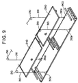
- a heat exchanger 1600, an air blower 1000, etc. are accommodated in the unit body 2000 as shown in Fig. 9.
- a decorative panel 700 having air blow-out ports 400 at the both ends thereof is fixed to the lower end of the unit body 2000, and a filter receiving member 501 of metal plate is engagedly held at an inward portion of the center opening of the decorative panel 700.
- air filters 240 are brought into contact with receiving portions 501a of the filter receiving member 501, and a center panel (elevating panel) 900 of metal plate is provided at the front portion of the center opening of the decorative panel 700 so that a space serving as an air suck-in port 300 remains at each of both the sides thereof.
- the air filters 240 are mounted on the center panel 900 through leg portions 100, and these air filters 240 are suspended to the decorative panel 700 through four ropes 310 so as to be freely movable upwardly and downwardly relatively to the decorative panel 700.
- respective one ends 310a of the four suspending ropes 310 are fixed to the center panel 900 at suitable four places thereof.
- the other ends of the four suspending ropes 310 are extended upwardly, wound around the rollers 210, extended in a substantially horizontal direction and then linked to an elevating mechanism 1500 having the same construction as the first embodiment.
- the elevating mechanism 1500 is fixed onto a metal plate 1510 which is bridged substantially at the center of the open portion of the decorative panel 700 as shown in Fig. 8.
- the air filters 240 are provided on the center panel 900 of metal plate through the leg portions 100. Therefore, even when vibration occurs during the upward or downward motion of the center panel 900, dust which is attached to the air filters 240 falls onto the upper surface of the center panel, and collected there. Accordingly, during a work of replacing the air filters 240 or the like, the dust attached to the filters 240 is prevented from falling onto the floor, and thus this makes the room very sanitary. Therefore, even when the present invention is applied to air conditioners in factories, stores, etc. for food, the trouble due to falling of dust can be perfectly avoided.
- the operation stop command is output to stop the elevating motor. Therefore, when the elevating panel arrives at the upper limit position, the elevating panel can be stopped. In this case, the number of parts can be reduced, so that the cost can be lowered and the failure rate can be also reduced.
- the elevating panel when in the progress of the downward motion of the elevating panel, the elevating panel arrives at the lower limit position and the consumption current is equal to the set value or more, the elevating motor can be immediately stopped. In this case, the number of parts can be also reduced, so that the cost can be lowered and the failure rate can be reduced.
- the motion of the elevating panel can be freely switched between the upward motion and the downward motion, and the above effect can be obtained in both the upward motion and the downward motion of the elevating panel.
- the elevating motor is set to be stopped after a predetermined time elapses. Therefore, after the elevating panel arrives at the upper limit position, the elevating panel can be stopped after the four comers of the elevating panel can be brought into close contact with the bottom face of the in-ceiling type air conditioner to correct the inclination of the elevating panel. In this case, the number of parts can be reduced, so that the cost can be lowered and the failure rate can be also reduced.
- the elevating motor when the consumption current is over the set value in the progress of the upward motion of the elevating panel, the elevating motor is set to be stopped after a predetermined time elapses. Therefore, after the elevating panel arrives at the upper limit position, the elevating panel can be stopped after the four corners of the elevating panel can be brought into close contact with the bottom face of the in-ceiling type air conditioner to correct the inclination of the elevating panel. In this case, the number of parts can be reduced, so that the cost can be lowered and the failure rate can be also reduced.
Landscapes
- Engineering & Computer Science (AREA)
- Chemical & Material Sciences (AREA)
- Combustion & Propulsion (AREA)
- Mechanical Engineering (AREA)
- General Engineering & Computer Science (AREA)
- Air Filters, Heat-Exchange Apparatuses, And Housings Of Air-Conditioning Units (AREA)
- Air Conditioning Control Device (AREA)
Description
- The present invention relates to an improvement of an in-ceiling type air conditioner having a control system for controlling the upward and downward motion of a panel which is upwardly and downwardly movable (hereinafter referred to as "elevating panel") and provided with an air filter for cleaning suck-in air into the in-ceiling type air conditioner.
- There has been generally known an in-ceiling type air conditioner in which an air suction grill having an elevating panel is supported so as to be freely upwardly and downwardly moved relatively to the lower face of a decorative panel by using an elevating motor. In this type of air conditioner, a work for replacing an air filter with a new one can be performed at a lower place because an air suction grill provided with the air filter is controllable to be downwardly moved to the lower place (see for example JP-06 026 667).
- The conventional in-ceiling type air conditioner as described above is provided with upper and lower limits switches for detecting the upper limit position and the lower limit position of the elevating panel, respectively. When the air suction grill is downwardly moved and stopped at the lower limit position, the elevating motor is stopped on the basis of a signal from the lower limit switch which is adapted to detect the lower limit position. On the other hand, when the air suction grill is upwardly moved and stopped at the upper limit position, the elevating motor is stopped on the basis of a signal from the upper limit switch which is adapted to detect the upper limit position.
- Particularly when the air suction grill is stopped at the upper limit position, the air suction grill is upwardly moved until the four comers of the air suction grill uniformly come into contact with the lower face of the decorative panel so that the air suction grill is not inclined, and then stopped at that position while keeping a horizontal position.
- In the prior art, a limit switch must be provided to stop the air suction grill at the upper limit position or the lower limit position as described above, resulting in increase of the number of parts and the number of electrical wires and also disturbing the reduction in cost. In addition, the rate of failure is also increased.
- Therefore, an object of the present invention is to provide an in-ceiling type air conditioner in which the number of parts and the number of electrical wires are reduced, a air suction grill can be stopped at the upper limit position or the lower limit position at a low failure rate and at a low cost, and also the inclination of the air suction grill can be corrected when the air suction grill is stopped at the upper limit position.
- In order to attain the above object, according to the present invention, an in-ceiling type air conditioner includes a unit body which contains a heat exchanger and an air blower and is mounted in the ceiling, a decorative panel provided on the ceiling face, and an elevating panel with an air filter, to which one ends of suspending ropes are fixed, the other ends of the suspending ropes being fixed to pulleys which are rotationally driven by an elevating motor, the suspending ropes being unreeled/rewound by actuating the elevating motor to move the elevating panel upwardly and downwardly, is characterized by further including consumption current detecting means for detecting the consumption current of the elevating motor, stop instructing means for outputting an operation stop instruction when the detection result of the consumption current detecting means is over a predetermined set value during the upward or downward motion of the elevating panel, and motor stop control means for stopping the elevating motor in response to the operation stop instruction from the stop instruction means.
- According to the present invention, when the elevating panel is being upwardly moved, the consumption current of the elevating motor is kept constant. However, when the elevating panel arrives at the upper limit position, the load imposed on the elevating motor increases, and finally it is over a predetermined value. In this case, the consumption current detecting means detects this situation, the operation stop instruction is output to the motor stop control means, and the motor stop control means stops the elevating motor, whereby the elevating panel is stopped at the upper lower limit position. Further, when the elevating panel is downwardly moved to the lower limit position, the rotation of the elevating motor is continued. Therefore, the rotation of the pulleys works to rewind the ropes after all the ropes are unreeled. The load of the elevating motor when the ropes are unreeled relatively small, and thus a relatively small consumption current is detected by the consumption current detecting means. However, the load on the elevating motor when the ropes are rewound after the ropes are unreeled, becomes relatively larger than the dead weight of the elevating panel, and thus the consumption current is increased. Therefore, the consumption current detecting means detects a relatively large consumption current. If the consumption current detected by the consumption current detecting means exceeds a predetermined set value, the operation stop signal is output from the stop instruction means, and the motor stop control means stops the elevating motor.
- In the in-ceiling type air conditioner as described above, the stop instruction means outputs the operation stop instruction when the detection result of the consumption current detecting means is over a first set value during the upward motion of the elevating panel, or when the detection result of the consumption current detecting means is over a second set value during the downward motion of the elevating panel.
- According to the above in-ceiling type air conditioner as described above, for example when the load on the elevating motor increases in the progress of the upward motion of the elevating panel to the upper limit position and the consumption current finally exceeds the first set value, the timer is started, and the elevating motor is stopped after the predetermined time elapses. The first set value is set to a value larger than the consumption current which is took by the elevating motor when the elevating grill is upwardly moved, and it is predetermined in accordance with the load of the elevating motor which is increased when the elevating panel arrives at the upper limit position. Further, when the load on the elevating motor is increased in the progress of the lower limit position of the elevating panel and the consumption current finally exceeds the second set value, the elevating motor is immediately stopped. The second set value is set to be smaller than the first set value, and it is set on the basis of the consumption current which is took by the elevating motor when the elevating panel is upwardly moved.
- In the in-ceiling type air conditioner as described above, the motor stop control means stops the elevating motor when a predetermined time elapses after receiving the operation stop instruction from the stop instruction means.
- According the above in-ceiling type air conditioner as described above, the elevating motor is stopped after the predetermined time elapses from the time when the operation stop instruction is output from the stop instruction means. Therefore, after the elevating panel arrives at the upper limit position, the elevating motor is rotated for the predetermined time to correct the inclination of the elevating panel.
- The in-ceiling type air conditioner as described above further includes a timer for counting the predetermined time after the operation stop instruction is output, wherein the motor stop control means stops the elevating motor in response to the output result of the timer.
- Further, according to the present invention, a control device for controlling the upward and downward motion of an elevating panel of an in-ceiling type air conditioner, comprising, an elevating motor for moving the elevating panel upwardly and downwardly, a driver circuit for supplying an operating current to the elevating motor to rotate the elevating motor forwardly and backwardly, a controller for outputting a control signal to the driver circuit and controlling the driver circuit on the basis of the control signal, a consumption current detector for detecting the consumption current of the elevating motor at all times to output a detection result to the controller, a timer for counting a predetermined time and outputting the count result to the controller, wherein when the consumption current detected by the consumption current detector exceeds a predetermined value during the upward or downward motion of the elevating panel, the controller outputs an operation stop instruction to the driver circuit to stop the rotation of the elevating motor and thus stop the elevating panel.
- When the control device as described above is installed into an in-ceiling type air conditioner, the same effects as described above can be obtained.
- According to the control device as described above, the predetermined time is set to such an enough time that the overall periphery of said elevating panel can perfectly arrive at the upper limit position of the upward motion or at the lower limit position of the downward motion thereof. Therefore, the elevating panel can be stopped at the upper or lower limit position while it is surely kept in a horizontal position when arriving at the upper limit position or lower limit position.
-
- Fig. 1 is a perspective view showing an embodiment of an in-ceiling type air conditioner;
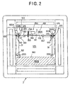
- Fig. 2 is a plane view showing a air suction grill;
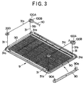
- Fig. 3 is a perspective view showing the state where the air suction grill is suspended;
- Fig. 4 is a longitudinal sectional view showing the in-ceiling type air conditioner;
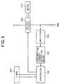
- Fig. 5 is a block diagram showing a control system for the air conditioner of the present invention;
- Fig. 6 is a flowchart showing a processing flow at the front stage of the present invention;
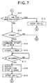
- Fig. 7 is a flowchart showing a processing flow at the rear stage of the present invention;
- Fig. 8 is a perspective view showing another embodiment of the in-ceiling type air conditioner of the present invention;
- Fig. 9 is a cross-sectional view showing the in-ceiling type air conditioner shown in Fig. 8; and
- Fig. 10 is a perspective view showing a center panel.
-
- Preferred embodiments according to the present invention will be described with reference to the accompanying drawings.
- Fig. 4 is a longitudinal sectional view showing an in-ceiling type air conditioner. In Fig. 4,
reference numeral 50 represents an air conditioner. - The
air conditioner 50 includes a unitmain body 2 which is mounted in theceiling 1 and formed of a metal plate, adecorative panel 7 which has an air suck-inport 3 at the center thereof and air blow-outports 4 on the four sides of the peripheral portion thereof and provided in the ceiling plane so as to close aceiling hole 5, and a air suction grill 9 (elevating panel) having an air suck-inport 8 at the center thereof. -
Reference numeral 10 represents an air blower which comprises a turbo fan 11 and afan motor 13 secured on theceiling plate 12,reference numeral 14 represents a nozzle port for guiding indoor air from the air suck-inport 8 to the turbo fan 11,reference numeral 15 represents a drain pan which has an inwardly projectingportion 15a and an outwardly projecting portion 15b and is formed of styrolfoam in a squared annular form, andreference numeral 16 represents a plate fin type heat exchanger which is disposed at the discharge side of the turbo fan 11 so as to surround the fan annularly.Reference numeral 17 represents a heat insulator which is wound around the peripheral surface of theunit body 2,reference numeral 21 represents an air guide unit for guiding to an air blow-outport 4 air which is heat-exchanged by theheat exchanger 16,reference numeral 22 represents a suspending bolt through which theunit body 2 is suspended from a ceiling girder by a hook member, andreference numeral 24 represents an air filter which is secured at the downstream side of theair suction grill 9 and adapted to purity the suck-in air. - Referring to Figs. 1 to 3, the
air suction grill 9 is supported to theunit body 2 through foursuspending ropes 31 so as to be freely upwardly and downwardly moved. Each of the four suspendingropes 31 is formed of a resin wire or metal wire which is coated with vinyl coating on the outer periphery thereof, however, it may comprise a dial cord. As shown in Fig. 3, oneends 31a of the four suspendingropes 31 are connected tohooks 90a of air suctiongrill reinforcing members 90 as shown in Fig. 3, and theother ends 31c of two suspending ropes of the four suspendingropes 31 are wound aroundmain pulleys 100A while theother ends 31c of the other two suspendingropes 31 are wound aroundmain pulleys 100B throughrope guides 200 or auxiliary pulleys (not shown), respectively. - The air suction
grill reinforcing members 90 are fixed to the two sides of theair suction grill 9 by screws or the like and function as hooks for the foursuspending ropes 31. In addition, the air suctiongrill reinforcing members 90 also function to reinforce theair suction grill 9 and prevent the lateral displacement of the air filter 24 (Fig. 4) which is mounted on the suck-in face of theair suction grill 9. - As shown in Fig. 2, the totally four
main pulleys shaft 110 while eachpulley 100A and eachpulley 100B are paired. Each of themain pulleys shaft 110 is inserted into the holes of thesemain pulleys shaft 110 through the holes. Afixing member 120 is fixed to the shaft portion of theshaft 110 through plural screws or the like, and a rotational force transmitting means such as a leaf spring, an electromagnet or the like (hereinafter referred to as "coil spring") 130 is interposed between thefixing member 120 and themain pulley -
Reference numeral 125 represents a freely rotating ring. In such a situation that only the dead weight of theair suction grill 9 is applied to the four suspendingropes 31, the fixingmembers 120, themain pulleys coil spring 130, and the four suspendingropes 31 are unreeled/rewound interlockingly with the rotation of theshaft 110. However, when an excessive load is imposed on the four suspendingropes 31, themain pulleys coil spring 130. - Further, according to this embodiment, a
mechanism 150 for upwardly and downwardly moving the air suction grill 9 (hereinafter referred to as "elevating mechanism"), that is, the elevatingmechanism 150 comprising themain pulleys shaft 110, a clutch containing the rotational force transmitting means 130 and a air suction grill elevating motor (DC motor) 140 as described later, etc. are collectively disposed on asupport plate 151 which is provided so as to extend in the open portion of theunit body 2. - As shown in Fig. 2, the
support plate 151 is fixed to thedecorative panel 7, and the elevatingmechanism 150 described above is fixed to the decorative panel side. Further, acontroller 160 for controlling the air conditioner is provided in the open portion of theunit body 2 so as to confront thesupport plate 151. Thecontroller 160 and thesupport plate 151 are disposed so as to extend in the so-called air sucking open portion of theunit body 2. That is, thesupport plate 151 is disposed so as to extend in anarea 190A while thecontroller 160 is disposed so as to extend in anarea 190B, however, the existence of thesupport plate 151 and thecontroller 160 do not disturb the air sucking function because the air can be sufficiently sucked in through theresidual space 170. The elevatingmechanism 150 described above is fixed to thedecorative panel 7, however, thecontroller 160 is fixed to theunit body 2. - The elevating
mechanism 150 will be hereunder described in detail. - The
shaft 110 is freely rotatably mounted on thesupport plate 151 through twobearings 152. Agear 153 is fixed to the substantially center portion of theshaft 110. Thegear 153 is engaged with a gear 154, and the gear 154 is fixed to the output shaft of themotor 140 for elevating (upwardly and downwardly moving) the air suction grill as described above.Reference numeral 141 represents a capacitor for the motor, andreference numeral 143 represents a timer for correction. - A pull switch (operating switch) is provided as an instructing unit to move the
air suction grill 9 upwardly and downwardly as shown in Fig. 1. A rotary type pull switch is used as thepull switch 51, upon repetitive pull operation of the switch, the air suctiongrill elevating motor 140 repetitively performs "forward rotation", "stop" and "backward rotation" in this order, and thus theair suction grill 9 also repetitively performs "downward motion", "stop", "upward motion" and "stop" in this order. As described above, the air suction grill repeats "downward motion", "stop", "upward motion" and "stop" in this order by operating the rotary switch, so that the air suction grill can be stopped at any position by a simple operation. - Next, means for stopping the elevating
motor 140 when theair suction grill 9 reaches the upper limit position or the lower limit position will be described with reference to Fig. 5. - In response to an instruction from the
pull switch 51, thecontroller 160 outputs to a driver circuit 305 a control signal for controlling the forward rotation and the backward rotation of the elevatingmotor 140. In response to the control signal from thecontroller 160, thedriver circuit 305 drives the elevatingmotor 140 at a predetermined speed. - When the elevating
motor 140 is rotated in one direction to upwardly move theair suction grill 9, the consumption current IC output from thedriver circuit 305 to the motor is equal to about 170mA while the air suction grill does not reach the upper limit position. However, when theair suction grill 9 reaches the upper limit position (at least one comer (or side) of theair suction grill 9 abuts against the decorative panel 7), the elevatingmotor 140 is rotated against the frictional force which occurs between themain pulleys motor 140 is increased by the amount corresponding to the frictional force. Therefore, the consumption current IC output from thedriver 305 for the elevatingmotor 140 is also increased. At this time, for example, the consumption current IC of themotor 140 ranges from about 300 mA to about 350 mA. - When the elevating
motor 140 is rotated in the other direction to downwardly move theair suction grill 9, the consumption current IC for the elevatingmotor 140 is equal to about 60 mA while theair suction grill 9 does not reach the lower limit position. However, the elevatingmotor 140 is still rotated by thedriver circuit 305 even when theair suction grill 9 reaches the lower limit position, and thus the consumption current IC is increased to the range from about 100 mA to about 170 mA. That is, when the elevatingmotor 140 is still rotated even after theair suction grill 9 reaches the lower limit position as described above, thepulleys ropes 31 after the whole suspending ropes are unreeled therefrom. When thepulleys ropes 31, the substantially same load as when theair suction grill 9 is upwardly moved is imposed on the elevatingmotor 140, and thus the consumption current IC of the elevatingmotor 140 is increased to the range from about 100 mA to about 170 mA. - The
driver circuit 305 is connected to consumption current detecting means 307 through anamplifier 303. The consumption current detecting means 307 detects the consumption current IC of the elevatingmotor 140 at all times, and inputs the consumption current IC thus detected to thecontroller 160. - When the
air suction grill 9 is in the progress of the upward motion and the consumption current IC is increased from 170mA to 300mA (first set value X) or more, thecontroller 160 outputs an operation stop command of the elevatingmotor 140, and also when theair suction grill 9 is in the progress of the downward motion and the consumption current IC is increased from 60mA to 100mA (second set value Y) or more, thecontroller 160 outputs the operation stop command of the elevatingmotor 140. - When the operation stop command for the elevating
motor 140 is output, the output of the control signal to thedriver circuit 305 is intercepted to stop the driving of the elevatingmotor 140. However, even if the operation stop command for the elevatingmotor 140 is output when the air suction grill is being upwardly moved and the consumption current IC is increased from 170mA to 300mA (first set value X) or more, the output of the control signal to thedriver circuit 305 is not intercepted unless a predetermined time (for example, 4 seconds) is counted by atimer 309, and at the time when the predetermined time (for example, 4 seconds) is counted, the output of the control signal to thedriver circuit 305 is intercepted to stop the driving of the elevatingmotor 140. - In the case of the upward motion of the
air suction grill 9, in some cases a time difference may occur in rewinding time among the four suspendingropes 31 fixed to theair suction grill 9, and thus even when theair suction grill 9 arrives at the upper limit position at one suspending rope side, it does not completely arrive at the upper limit position at the other suspending rope sides, so that theair suction grill 9 is not perfectly upwardly moved to the upper limit position. The predetermined time as described above is set to an enough time which is needed until the other suspending ropes are also perfectly rewound up after one suspending rope is perfectly rewound up. - Next, the operation of this embodiment will be described with reference to Figs. 6 and 7.
- In step S1, it is first judged whether the
pull switch 51 is manipulated. Thepull switch 51 may be manipulated by using a pull-down rod or the like to pull thepull switch 51. When it is judged that thepull switch 51 is manipulated, in step S2 the control signal to rotate the elevatingmotor 140 forwardly is output from the controller 301, and input to thedriver circuit 305 to forwardly rotate the elevatingmotor 140 and downwardly move theair suction grill 9. In step S3, the consumption current IC for the elevatingmotor 140 which is output from thedriver circuit 305 is detected by the consumptioncurrent detecting means 307. In this case, theair suction grill 9 is in the progress of the downward motion to the lower limit position, and thus it detects the consumption current IC of about 60mA as a detection value. - In step S4, it is judged whether the
pull switch 51 is manipulated again. If thepull switch 51 is judged to be manipulated, the process goes to step S8 to intercept the current flow into the elevatingmotor 140 and stop theair suction grill 9. However, if thepull switch 51 is not manipulated, the process goes to step S5 and thecontroller 160 judges whether the consumption current IC increases to 100mA or more as the second set value Y. If the consumption current IC does not increase to the second set value Y, the process returns to the step S3. On the other hand, if the consumption current IC increases to the second set value Y, the process goes to step S6 to output the operation stop signal from thecontroller 160. - In step S7, the controller 301 intercepts the control signal to be output to the
driver circuit 305, whereby the current to be supplied to the elevatingmotor 140 is intercepted and theair suction grill 9 is stopped. Thereafter, the process goes to step S9. - In step S9, it is judged whether the
pull switch 51 is manipulated. If thepull switch 51 is not manipulated, the process returns to the step S8. However, if thepull switch 51 is manipulated, the process goes to step S10 to output from the controller 301 the control signal for backwardly rotating the elevatingmotor 140, and the control signal is input to thedriver circuit 305 to backwardly rotate the elevatingmotor 140 and upwardly theair suction grill 9. In step S11, the consumption current IC of the elevatingmotor 140 is detected by the consumptioncurrent detecting means 307. In this case, theair suction grill 9 is in the progress of the upward motion to the upper limit position, and thus the detection value of the consumption current IC is equal to about 170mA, for example. - In step S12, it is judged whether the
pull switch 51 is manipulated again. If thepull switch 51 is manipulated, the process goes to step S13 in which the controller 301 intercepts the current to be supplied to the elevatingmotor 140 and theair suction grill 9 is stopped. However, if thepull switch 51 is not manipulated, the process goes to step S14 in which thecontroller 160 judges whether the consumption current IC increases to the first set value X, for example, 300mA or more. If the consumption current IC does not reach the first set value X, the process returns to the step S10. However, if the consumption current IC reaches the first set value X, a start command is output from thecontroller 160 to thetimer 309 in step S15, and then the process goes to stepS 16. - In step S16, in response to the start command, the
timer 309 is started. The set time of thetimer 309 is set to 4 seconds, for example. In step S17, it is judged when the time counted by thetimer 309 reaches the set time (for example, 4 seconds). If the count time of thetimer 309 is beyond 4 seconds, the process goes to step S18 to output the operation stop signal from the controller 301, and then the process goes to step S19. In step S19, the controller 301 which outputs the operation stop signal intercepts the control signal to be output to thedriver circuit 305, whereby the elevatingmotor 140 is stopped and thus theair suction grill 9 is stopped. Thereafter, the process returns to the step S1. - That is, when the
air suction grill 9 arrives at the upper limit position, thetimer 309 counts the set time (4 seconds) and then the elevatingmotor 140 is stopped. Therefore, the elevatingmotor 140 continues to be rotated for 4 seconds. During this time (4 seconds), themain pulleys ropes 31 are strongly rewound, whereby the four comers of theair suction grill 9 is substantially surely brought into close contact with thedecorative panel 7. - According to this embodiment of the present invention, in the process of the downward motion of the
air suction grill 9, the downward motion of theair suction grill 9 is stopped (S8) by pulling thepull switch 51 as described above, so that theair suction grill 9 can be temporarily stopped at any position. Although the illustration is omitted from Fig. 1, the air cleaning filter 24 (Fig. 4) is mounted on the upper portion of theair suction grill 9. Therefore, when theair suction grill 9 is pulled down from theceiling 6 and temporarily stopped, the works of replacing thefilter 24, cleaning thefilter 24, etc. can be performed at a lower place. Accordingly as compared with works at a higher place, not only the works can be more readily performed, but also the safety for the works can be enhanced. - That is, according to this embodiment, by operating the
pull switch 51 to drive themotor 140 for elevating the air suction grill, theshaft 110 is driven to rotate themain pulleys shaft 110, and the suspendingropes 31 which are wound around themain pulleys air suction grill 9 upwardly and downwardly. Therefore, when a maintenance work is performed on theair cleaning filter 24, the work may be performed after theair cleaning filter 24 is pulled down to the lower position (or any position). - Further, it is sufficient to provide only one
motor 140 for elevating the air suction grill, and thus the cost-up can be suppressed, and the construction becomes simpler and the trouble rate can be reduced to a smaller level as compared with the case whereplural motors 140 for elevating the air suction grill are provided. Further, when an excessive load is imposed, the clutch operates to make theshaft 110 turn free, so that the burning of themotor 140 can be prevented. - According to this embodiment, when the
air suction grill 9 is downwardly moved, the consumption current IC supplied to the elevatingmotor 140 is detected, and theair suction grill 9 is regarded as arriving at the lower limit position when the consumption current IC increases from 60mA to 100mA. At this time, the current to be supplied to the elevatingmotor 140 is intercepted to stop the elevatingmotor 140, whereby theair suction grill 9 is stopped. Therefore, as compared with the case where theair suction grill 9 is stopped at the lower limit position by using a mechanical mechanism such as a limit switch or the like, the number of parts can be reduced to a smaller value, the construction can be more simplified, the cost can be more greatly reduced and the trouble rate can be also more lowered. - Likewise, when the
air suction grill 9 is upwardly moved, the consumption current IC supplied to the elevatingmotor 140 is detected, and theair suction grill 9 is regarded as arriving at the upper limit position when the consumption current IC increases from 170mA to 300mA. At this time, the current to be supplied to the elevatingmotor 140 is intercepted to stop the elevatingmotor 140, whereby theair suction grill 9 is stopped. Therefore, as compared with the case where theair suction grill 9 is stopped at the lower limit position by using a mechanical mechanism such as a limit switch or the like, the number of parts can be reduced to a smaller value, the construction can be more simplified, the cost can be more greatly reduced and the trouble rate can be also more lowered. - Further, when the
air suction grill 9 is suspended by the suspendingropes 31, the four suspending ropes are not necessarily kept equal in length so that theair suction grill 9 is kept in a horizontal position. That is, theair suction grill 9 may be lifted with being inclined. However, according to this embodiment, even when theair suction grill 9 is lifted in an inclined position, thetimer 309 operates to count the predetermined time (for example, 4 seconds) after theair suction grill 9 arrives at the upper limit position, and then the rotation of the elevatingmotor 140 is stopped after 4 seconds elapses. During this predetermined time, the rotation of themain pulleys ropes 31 are perfectly rewound, so that theair suction grill 9 is perfectly lifted up until it is kept in a horizontal position and brought into close contact with thedecorative panel 7. In this case, themain pulley ropes 31 has been perfectly rewound is stopped against the rotation on the shaft portion of theshaft 110 as described above. - Further, even if any unbalance in length occurs between the four suspending
ropes 31 in the progress of the rewinding operation of the suspendingropes 31, when theair suction grill 9 has been finally rewound, the unbalance in length between the suspendingropes 31 is absorbed by the stop of themain pulleys air suction grill 9 is brought into perfectly close contact with thedecorative panel 7 and no gap occurs therebetween. - Still further, according to this embodiment, the
controller 160, the consumption current detecting means 307 and thetimer 309, that is, a small number of parts are used as a mechanism for stopping theair suction grill 9 at the upper limit position after theair suction grill 9 is upwardly moved, so that the cost can be reduced by the amount corresponding to the reduced number of parts, and also the failure rate can be reduced. - The upwardly moved
air suction grill 9 may be fixed to the decorative panel through air suction grill lock means (not shown). However, the lock means is not indispensable, and it is omitted in this embodiment. As a simple air suction grill lock means, amagnet 43 may be provided to thedecorative panel 7 as shown in Fig. 1 to lock theair suction grill 9 by themagnet 43. - The present invention is not limited to the above embodiment, and various modifications may be made.
- For example, the means for absorbing the different in length between the suspending ropes fixed to the right and left sides of the
air suction grill 9 after theair suction grill 9 arrives at the upper limit position is not limited to the combination of themain pulleys timer 309. For example, a lever for pulling up the suspendingropes 31 by a spring force may be provided between themain pulley 100B and therope guide 200. - In this case, when the
air suction grill 9 arrives at the upper limit position while being inclined, the tension of the suspendingrope 31 at one of the right and left sides of theair suction grill 9, which first arrives at the upper limit position, is increased, and it pulls down the lever against the spring force. Therefore, the suspendingrope 31 is rewound by the amount corresponding to the pull-down of the lever. Accordingly, the other side of theair suction grill 9 which does not reach the upper limit position can be upwardly moved to the upper limit position. - Besides, the rope guides 200 may be designed to be upwardly urged by the spring force. In this case, when the
air suction grill 9 arrives at the upper limit position while being inclined, the tension of the suspendingrope 31 at one of the right and left sides of theair suction grill 9, which first arrives at the upper limit position, is increased, and it pushes down therope guide 200 against the spring force. Therefore, the suspendingrope 31 is rewound by the amount corresponding to the push-down of therope guide 200. Accordingly, the other side of theair suction grill 9 which does not reach the upper limit position can be upwardly moved to the upper limit position. - Further, the present invention is applied to an air conditioner having no air suck-in port in the elevating panel as shown in Figs. 8 to 10.
- In Fig. 8,
reference numeral 2000 represents a box type unit body which is embedded in the ceiling. Aheat exchanger 1600, anair blower 1000, etc. are accommodated in theunit body 2000 as shown in Fig. 9. Further, adecorative panel 700 having air blow-outports 400 at the both ends thereof is fixed to the lower end of theunit body 2000, and afilter receiving member 501 of metal plate is engagedly held at an inward portion of the center opening of thedecorative panel 700. Further,air filters 240 are brought into contact with receiving portions 501a of thefilter receiving member 501, and a center panel (elevating panel) 900 of metal plate is provided at the front portion of the center opening of thedecorative panel 700 so that a space serving as an air suck-inport 300 remains at each of both the sides thereof. - As shown in Fig. 8, the
air filters 240 are mounted on thecenter panel 900 throughleg portions 100, and theseair filters 240 are suspended to thedecorative panel 700 through fourropes 310 so as to be freely movable upwardly and downwardly relatively to thedecorative panel 700. - As shown in Fig. 10, respective one ends 310a of the four suspending
ropes 310 are fixed to thecenter panel 900 at suitable four places thereof. The other ends of the four suspendingropes 310 are extended upwardly, wound around therollers 210, extended in a substantially horizontal direction and then linked to an elevatingmechanism 1500 having the same construction as the first embodiment. The elevatingmechanism 1500 is fixed onto ametal plate 1510 which is bridged substantially at the center of the open portion of thedecorative panel 700 as shown in Fig. 8. - According to the present invention, the
air filters 240 are provided on thecenter panel 900 of metal plate through theleg portions 100. Therefore, even when vibration occurs during the upward or downward motion of thecenter panel 900, dust which is attached to theair filters 240 falls onto the upper surface of the center panel, and collected there. Accordingly, during a work of replacing theair filters 240 or the like, the dust attached to thefilters 240 is prevented from falling onto the floor, and thus this makes the room very sanitary. Therefore, even when the present invention is applied to air conditioners in factories, stores, etc. for food, the trouble due to falling of dust can be perfectly avoided. - According to the present invention, when the detection result of the consumption current detecting means is beyond the predetermined set value in the progress of the upward motion of the elevating panel, the operation stop command is output to stop the elevating motor. Therefore, when the elevating panel arrives at the upper limit position, the elevating panel can be stopped. In this case, the number of parts can be reduced, so that the cost can be lowered and the failure rate can be also reduced.
- According to the present invention, when in the progress of the downward motion of the elevating panel, the elevating panel arrives at the lower limit position and the consumption current is equal to the set value or more, the elevating motor can be immediately stopped. In this case, the number of parts can be also reduced, so that the cost can be lowered and the failure rate can be reduced.
- According to the present invention, the motion of the elevating panel can be freely switched between the upward motion and the downward motion, and the above effect can be obtained in both the upward motion and the downward motion of the elevating panel. When the consumption panel is over the set value in the progress of the upward motion of the elevating panel, the elevating motor is set to be stopped after a predetermined time elapses. Therefore, after the elevating panel arrives at the upper limit position, the elevating panel can be stopped after the four comers of the elevating panel can be brought into close contact with the bottom face of the in-ceiling type air conditioner to correct the inclination of the elevating panel. In this case, the number of parts can be reduced, so that the cost can be lowered and the failure rate can be also reduced.
- According to the present invention, when the consumption current is over the set value in the progress of the upward motion of the elevating panel, the elevating motor is set to be stopped after a predetermined time elapses. Therefore, after the elevating panel arrives at the upper limit position, the elevating panel can be stopped after the four corners of the elevating panel can be brought into close contact with the bottom face of the in-ceiling type air conditioner to correct the inclination of the elevating panel. In this case, the number of parts can be reduced, so that the cost can be lowered and the failure rate can be also reduced.
Claims (6)
- An in-ceiling type air conditioner including an unit body which contains a heat exchanger and an air blower and is mounted in the ceiling, a decorative panel provided on the ceiling face, and an elevating panel with an air filter, to which one ends of suspending ropes are fixed, the other ends of the suspending ropes being fixed to pulleys which are rotationally driven by an elevating motor, said suspending ropes being unreeled/rewound by actuating said elevating motor to move said elevating panel upwardly and downwardly, characterized in that said in-ceiling type air conditioner further including:consumption current detecting means for detecting the consumption current of said elevating motor;stop instructing means for outputting an operation stop instruction when the detection result of said consumption current detecting means is over a predetermined set value during the upward or downward motion of said elevating panel; andmotor stop control means for stopping said elevating motor in response to the operation stop instruction from said stop instruction means.
- The in-ceiling type air conditioner as claimed in claim 1, wherein said stop instruction means outputs the operation stop instruction when the detection result of said consumption current detecting means is over a first set value during the upward motion of said elevating panel, or when the detection result of said consumption current detecting means is over a second set value during the downward motion of said elevating panel.
- The in-ceiling type air conditioner as claimed in claim 1 or 2, wherein said motor stop control means stops said elevating motor when a predetermined time elapses after receiving the operation stop instruction from said stop instruction means.
- The in-ceiling type air conditioner as claimed in claim 3, further including a timer for counting the predetermined time after the operation stop instruction is output, wherein said motor stop control means stops said elevating motor in response to the output result of said timer.
- A control device for controlling the upward and downward motion of an elevating panel of an in-ceiling type air conditioner, comprising:an elevating motor for moving said elevating panel upwardly and downwardly;a driver circuit for supplying an operating current to said elevating motor to rotate said elevating motor forwardly and backwardly;a controller for outputting a control signal to said driver circuit and controlling said driver circuit on the basis of the control signal;a consumption current detector for detecting the consumption current of said elevating motor at all times to output a detection result to said controller;a timer for counting a predetermined time and outputting the count result to said controller, wherein when the consumption current detected by said consumption current detector exceeds a predetermined value during the upward or downward motion of said elevating panel, said controller outputs an operation stop instruction to said driver circuit to stop the rotation of said elevating motor and thus stop said elevating panel.
- The control device as claimed in claim 5, wherein the predetermined time is set to such an enough time that the overall periphery of said elevating panel can perfectly arrive at the upper limit position of the upward motion or at the lower limit position of the downward motion thereof, whereby said elevating panel is kept in a horizontal position when arriving at the upper limit position or lower limit position.
Applications Claiming Priority (3)
| Application Number | Priority Date | Filing Date | Title |
|---|---|---|---|
| JP22596296 | 1996-08-08 | ||
| JP225962/96 | 1996-08-08 | ||
| JP22596296A JP3552851B2 (en) | 1996-08-08 | 1996-08-08 | Ceiling-mounted air conditioner |
Publications (3)
| Publication Number | Publication Date |
|---|---|
| EP0823598A2 EP0823598A2 (en) | 1998-02-11 |
| EP0823598A3 EP0823598A3 (en) | 2001-04-11 |
| EP0823598B1 true EP0823598B1 (en) | 2003-11-19 |
Family
ID=16837620
Family Applications (1)
| Application Number | Title | Priority Date | Filing Date |
|---|---|---|---|
| EP97113236A Expired - Lifetime EP0823598B1 (en) | 1996-08-08 | 1997-07-31 | In-ceiling type air conditioner having controller for upward and downward motion of elevating panel |
Country Status (7)
| Country | Link |
|---|---|
| EP (1) | EP0823598B1 (en) |
| JP (1) | JP3552851B2 (en) |
| KR (1) | KR100458541B1 (en) |
| CN (1) | CN1100237C (en) |
| DE (1) | DE69726228T2 (en) |
| ES (1) | ES2212017T3 (en) |
| PT (1) | PT823598E (en) |
Families Citing this family (18)
| Publication number | Priority date | Publication date | Assignee | Title |
|---|---|---|---|---|
| JP4224276B2 (en) * | 2002-10-15 | 2009-02-12 | 東芝キヤリア株式会社 | Embedded ceiling air conditioner |
| CN100432548C (en) * | 2004-09-24 | 2008-11-12 | 乐金电子(天津)电器有限公司 | Indoor unit for ceiling air conditioner |
| CN1888691B (en) * | 2005-06-30 | 2010-08-25 | 乐金电子(天津)电器有限公司 | Control device and control method for lift grille of air conditioner |
| JP3998032B1 (en) * | 2006-04-18 | 2007-10-24 | ダイキン工業株式会社 | Air conditioner indoor unit |
| KR100725816B1 (en) * | 2006-07-10 | 2007-06-08 | 삼성전자주식회사 | Ceiling air conditioner and control method |
| KR101111728B1 (en) * | 2006-11-20 | 2012-02-15 | 삼성전자주식회사 | Ceiling air conditioners |
| KR100787502B1 (en) * | 2006-12-05 | 2007-12-21 | 삼성전자주식회사 | Ceiling air conditioners |
| KR101090093B1 (en) | 2009-02-25 | 2011-12-09 | 주식회사 엠.에스.라이팅 | Compound device for lighting and air-cleaning |
| KR101035010B1 (en) | 2009-02-25 | 2011-05-17 | 주식회사 엠.에스.라이팅 | Air Purification & Lighting Complex |
| JP5493495B2 (en) * | 2009-06-23 | 2014-05-14 | ダイキン工業株式会社 | Air conditioner indoor unit |
| CN103851697A (en) * | 2012-12-04 | 2014-06-11 | 海尔集团公司 | Hidden air conditioner |
| KR101662828B1 (en) * | 2015-04-14 | 2016-10-06 | (주)신한전기 | Up and down grill apparatus for ceiling type air conditioner |
| CN106091262B (en) * | 2016-06-17 | 2019-11-05 | 珠海格力电器股份有限公司 | Air conditioner panel control device and method |
| CN106931616A (en) * | 2017-04-14 | 2017-07-07 | 珠海格力电器股份有限公司 | Panel assembly and air conditioner with same |
| CN107687657B (en) * | 2017-08-04 | 2019-02-19 | 深圳市万佳安智能科技有限公司 | A kind of air purification equipment with cleaning function for kitchen |
| KR102235273B1 (en) * | 2017-12-21 | 2021-04-02 | 엘지전자 주식회사 | Ceiling type indoor unit of air conditioner |
| CN108332287A (en) * | 2018-01-04 | 2018-07-27 | 珠海格力电器股份有限公司 | Air conditioner indoor unit, control method thereof and air conditioner |
| KR102351602B1 (en) | 2021-09-09 | 2022-01-14 | 장현실 | Ceiling type air conditioner |
Family Cites Families (5)
| Publication number | Priority date | Publication date | Assignee | Title |
|---|---|---|---|---|
| JPH01315575A (en) * | 1988-06-15 | 1989-12-20 | Aichi Emerson Electric Co Ltd | Motor-driven blind |
| JP2532897Y2 (en) * | 1991-10-29 | 1997-04-16 | 三菱重工業株式会社 | Air conditioner |
| JPH0626667A (en) * | 1992-07-08 | 1994-02-04 | Mitsubishi Heavy Ind Ltd | Air-conditioner |
| JP2923150B2 (en) * | 1992-11-20 | 1999-07-26 | 三菱重工業株式会社 | Air conditioner |
| JP2528252B2 (en) * | 1993-05-10 | 1996-08-28 | 弘治 高林 | Ceiling mounted air conditioner |
-
1996
- 1996-08-08 JP JP22596296A patent/JP3552851B2/en not_active Expired - Fee Related
-
1997
- 1997-07-31 ES ES97113236T patent/ES2212017T3/en not_active Expired - Lifetime
- 1997-07-31 DE DE69726228T patent/DE69726228T2/en not_active Expired - Lifetime
- 1997-07-31 EP EP97113236A patent/EP0823598B1/en not_active Expired - Lifetime
- 1997-07-31 PT PT97113236T patent/PT823598E/en unknown
- 1997-08-07 KR KR1019970037739A patent/KR100458541B1/en not_active Expired - Fee Related
- 1997-08-08 CN CN97118568A patent/CN1100237C/en not_active Expired - Fee Related
Also Published As
| Publication number | Publication date |
|---|---|
| CN1177707A (en) | 1998-04-01 |
| ES2212017T3 (en) | 2004-07-16 |
| EP0823598A3 (en) | 2001-04-11 |
| PT823598E (en) | 2004-04-30 |
| JPH1054578A (en) | 1998-02-24 |
| EP0823598A2 (en) | 1998-02-11 |
| JP3552851B2 (en) | 2004-08-11 |
| DE69726228D1 (en) | 2003-12-24 |
| KR19980018467A (en) | 1998-06-05 |
| KR100458541B1 (en) | 2005-06-13 |
| DE69726228T2 (en) | 2004-09-02 |
| CN1100237C (en) | 2003-01-29 |
Similar Documents
| Publication | Publication Date | Title |
|---|---|---|
| EP0823598A2 (en) | In-ceiling type air conditioner having controller for upward and downward motion of elevating panel | |
| EP0768500B1 (en) | Elevation controller for air suction grille | |
| EP0783155B1 (en) | Method of labelling a device connected to a data bus | |
| EP0834704B1 (en) | Indoor unit of air-conditioner | |
| JP3087736B2 (en) | Air conditioner | |
| JP2923150B2 (en) | Air conditioner | |
| JP3507601B2 (en) | Ceiling-mounted air conditioner | |
| JP3615325B2 (en) | Embedded ceiling air conditioner | |
| JP3760449B2 (en) | Air conditioner | |
| JPH102578A (en) | Ceiling embedded air conditioner | |
| JP2001153395A (en) | Air conditioner | |
| JPH035503B2 (en) | ||
| CN216244604U (en) | Purification module and air duct machine | |
| JPH0921545A (en) | Air conditioner embedded in ceiling | |
| JP3895882B2 (en) | Air conditioner | |
| JPH0921546A (en) | Air conditioner embedded in ceiling | |
| KR0149911B1 (en) | Apparatus for controlling automatic shutter of airconditioner and method therefor | |
| JPH09178252A (en) | Ceiling-mounted air conditioner | |
| JPH06129705A (en) | Lift air conditioning grill | |
| JPH11132499A (en) | Ceiling-embedded type air conditioner | |
| JP3795950B2 (en) | Embedded ceiling air conditioner | |
| JP2005016767A (en) | Air conditioner | |
| JP2001235213A (en) | Air conditioning system | |
| JP3625593B2 (en) | Embedded ceiling air conditioner | |
| JPH10300120A (en) | Device for elevating/lowering grille of air conditioner |
Legal Events
| Date | Code | Title | Description |
|---|---|---|---|
| PUAI | Public reference made under article 153(3) epc to a published international application that has entered the european phase |
Free format text: ORIGINAL CODE: 0009012 |
|
| AK | Designated contracting states |
Kind code of ref document: A2 Designated state(s): DE ES FR GB GR IT PT |
|
| PUAL | Search report despatched |
Free format text: ORIGINAL CODE: 0009013 |
|
| AK | Designated contracting states |
Kind code of ref document: A3 Designated state(s): AT BE CH DE DK ES FI FR GB GR IE IT LI LU MC NL PT SE |
|
| RIC1 | Information provided on ipc code assigned before grant |
Free format text: 7F 24F 11/00 A, 7F 24F 1/00 B |
|
| 17P | Request for examination filed |
Effective date: 20010619 |
|
| AKX | Designation fees paid |
Free format text: DE ES FR GB GR IT PT |
|
| GRAH | Despatch of communication of intention to grant a patent |
Free format text: ORIGINAL CODE: EPIDOS IGRA |
|
| GRAS | Grant fee paid |
Free format text: ORIGINAL CODE: EPIDOSNIGR3 |
|
| GRAA | (expected) grant |
Free format text: ORIGINAL CODE: 0009210 |
|
| AK | Designated contracting states |
Kind code of ref document: B1 Designated state(s): DE ES FR GB GR IT PT |
|
| REG | Reference to a national code |
Ref country code: GB Ref legal event code: FG4D |
|
| REF | Corresponds to: |
Ref document number: 69726228 Country of ref document: DE Date of ref document: 20031224 Kind code of ref document: P |
|
| REG | Reference to a national code |
Ref country code: GR Ref legal event code: EP Ref document number: 20040400195 Country of ref document: GR |
|
| REG | Reference to a national code |
Ref country code: PT Ref legal event code: SC4A Free format text: AVAILABILITY OF NATIONAL TRANSLATION Effective date: 20040218 |
|
| REG | Reference to a national code |
Ref country code: ES Ref legal event code: FG2A Ref document number: 2212017 Country of ref document: ES Kind code of ref document: T3 |
|
| ET | Fr: translation filed | ||
| PLBE | No opposition filed within time limit |
Free format text: ORIGINAL CODE: 0009261 |
|
| STAA | Information on the status of an ep patent application or granted ep patent |
Free format text: STATUS: NO OPPOSITION FILED WITHIN TIME LIMIT |
|
| 26N | No opposition filed |
Effective date: 20040820 |
|
| PGFP | Annual fee paid to national office [announced via postgrant information from national office to epo] |
Ref country code: ES Payment date: 20140611 Year of fee payment: 18 Ref country code: GR Payment date: 20140620 Year of fee payment: 18 |
|
| PGFP | Annual fee paid to national office [announced via postgrant information from national office to epo] |
Ref country code: DE Payment date: 20140724 Year of fee payment: 18 |
|
| PGFP | Annual fee paid to national office [announced via postgrant information from national office to epo] |
Ref country code: FR Payment date: 20140708 Year of fee payment: 18 Ref country code: GB Payment date: 20140730 Year of fee payment: 18 |
|
| PGFP | Annual fee paid to national office [announced via postgrant information from national office to epo] |
Ref country code: PT Payment date: 20140203 Year of fee payment: 18 Ref country code: IT Payment date: 20140714 Year of fee payment: 18 |
|
| REG | Reference to a national code |
Ref country code: DE Ref legal event code: R082 Ref document number: 69726228 Country of ref document: DE |
|
| REG | Reference to a national code |
Ref country code: DE Ref legal event code: R119 Ref document number: 69726228 Country of ref document: DE |
|
| REG | Reference to a national code |
Ref country code: PT Ref legal event code: MM4A Free format text: LAPSE DUE TO NON-PAYMENT OF FEES Effective date: 20160201 |
|
| GBPC | Gb: european patent ceased through non-payment of renewal fee |
Effective date: 20150731 |
|
| PG25 | Lapsed in a contracting state [announced via postgrant information from national office to epo] |
Ref country code: DE Free format text: LAPSE BECAUSE OF NON-PAYMENT OF DUE FEES Effective date: 20160202 Ref country code: IT Free format text: LAPSE BECAUSE OF NON-PAYMENT OF DUE FEES Effective date: 20150731 Ref country code: GB Free format text: LAPSE BECAUSE OF NON-PAYMENT OF DUE FEES Effective date: 20150731 |
|
| REG | Reference to a national code |
Ref country code: FR Ref legal event code: ST Effective date: 20160331 |
|
| PG25 | Lapsed in a contracting state [announced via postgrant information from national office to epo] |
Ref country code: GR Free format text: LAPSE BECAUSE OF NON-PAYMENT OF DUE FEES Effective date: 20160202 Ref country code: FR Free format text: LAPSE BECAUSE OF NON-PAYMENT OF DUE FEES Effective date: 20150731 Ref country code: PT Free format text: LAPSE BECAUSE OF NON-PAYMENT OF DUE FEES Effective date: 20160201 |
|
| REG | Reference to a national code |
Ref country code: GR Ref legal event code: ML Ref document number: 20040400195 Country of ref document: GR Effective date: 20160202 |
|
| REG | Reference to a national code |
Ref country code: ES Ref legal event code: FD2A Effective date: 20160826 |
|
| PG25 | Lapsed in a contracting state [announced via postgrant information from national office to epo] |
Ref country code: ES Free format text: LAPSE BECAUSE OF NON-PAYMENT OF DUE FEES Effective date: 20150801 |