EP0823337B1 - Writing utensil - Google Patents
Writing utensil Download PDFInfo
- Publication number
- EP0823337B1 EP0823337B1 EP96908341A EP96908341A EP0823337B1 EP 0823337 B1 EP0823337 B1 EP 0823337B1 EP 96908341 A EP96908341 A EP 96908341A EP 96908341 A EP96908341 A EP 96908341A EP 0823337 B1 EP0823337 B1 EP 0823337B1
- Authority
- EP
- European Patent Office
- Prior art keywords
- cap
- extremity
- tip
- extremity end
- writing tool
- Prior art date
- Legal status (The legal status is an assumption and is not a legal conclusion. Google has not performed a legal analysis and makes no representation as to the accuracy of the status listed.)
- Expired - Lifetime
Links
Images




Classifications
-
- B—PERFORMING OPERATIONS; TRANSPORTING
- B43—WRITING OR DRAWING IMPLEMENTS; BUREAU ACCESSORIES
- B43K—IMPLEMENTS FOR WRITING OR DRAWING
- B43K23/00—Holders or connectors for writing implements; Means for protecting the writing-points
- B43K23/08—Protecting means, e.g. caps
- B43K23/12—Protecting means, e.g. caps for pens
-
- B—PERFORMING OPERATIONS; TRANSPORTING
- B43—WRITING OR DRAWING IMPLEMENTS; BUREAU ACCESSORIES
- B43K—IMPLEMENTS FOR WRITING OR DRAWING
- B43K1/00—Nibs; Writing-points
- B43K1/08—Nibs; Writing-points with ball points; Balls or ball beds
- B43K1/086—Nibs; Writing-points with ball points; Balls or ball beds with resilient supporting means for the ball, e.g. springs
-
- B—PERFORMING OPERATIONS; TRANSPORTING
- B43—WRITING OR DRAWING IMPLEMENTS; BUREAU ACCESSORIES
- B43K—IMPLEMENTS FOR WRITING OR DRAWING
- B43K5/00—Pens with ink reservoirs in holders, e.g. fountain-pens
- B43K5/18—Arrangements for feeding the ink to the nibs
- B43K5/1818—Mechanical feeding means, e.g. valves; Pumps
- B43K5/1827—Valves
- B43K5/1836—Valves automatically closing
- B43K5/1845—Valves automatically closing opened by actuation of the writing point
-
- B—PERFORMING OPERATIONS; TRANSPORTING
- B43—WRITING OR DRAWING IMPLEMENTS; BUREAU ACCESSORIES
- B43M—BUREAU ACCESSORIES NOT OTHERWISE PROVIDED FOR
- B43M11/00—Hand or desk devices of the office or personal type for applying liquid, other than ink, by contact to surfaces, e.g. for applying adhesive
- B43M11/06—Hand-held devices
- B43M11/08—Hand-held devices of the fountain-pen type
- B43M11/085—Hand-held devices of the fountain-pen type with ball points
Definitions
- This invention relates to a coating tool for correcting letters wrongly written by a writing tool such as ball-point pen or the like and more particularly a writing tool constructed such that air in the cap is pressurized and compressed during a step in which the cap is pushed and loaded in respect to the extremity end for holding the tip.
- a rotary member projects out of an end under an action of a spring and can be retracted inwardly against the spring toward the tip, so that the compressed air in the cap can be fed into the liquid tank to increase the inner pressure in the liquid tank.
- this kind of writing tool for example, a coating tool for correcting wrong letters by coating correction liquid
- a coating tool for correcting wrong letters by coating correction liquid for example, is constructed such that a rotary member held within the end of the tip is spring loaded and is closely contacted with the inward end seat of the tip to cause the end of the tip to be closed to prevent correction liquid from being discharged.
- the rotary member projected out of the extremity end of the tip is retracted inwardly of the tip in such a manner that the rotary member is spaced apart from the inward end seat of the tip against the spring to open the end of the tip, so that the correction liquid in the liquid tank can be discharged from the tip end during its use.
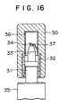
- an inner cylinder 32 for pressurizing and compressing air is arranged within a cap 30 to be closely contacted with an outer periphery of an extremity end 3.
- the cap 30 is pushed and loaded against the extremity end 31, air is pressurized and compressed in the inner cylinder 32, the rotary member 34 held in the extremity end of the tip 33 is retracted inwardly toward the tip in such a manner that the rotary member is moved away from the inward end seat of the tip 33, and the compressed air in the inner cylinder 32 is fed into the liquid tank 35 so as to increase the inner pressure in the liquid tank 35 (Japanese U.M. Laid-Open No. Hei 6-39169).
- the prior art writing tool is made such that during a step in which the cap 30 is loaded in respect to the extremity end 31, the inner cylinder 32 of the cap 30 is closely contacted with the outer periphery of the extremity end 31 to make a sealed space preventing air leakage within the inner cylinder 32 and the air in the inner cylinder 32 is pressurized and compressed under reduced volume of the sealingly closed space.
- the tongue of the valve opening member present in the cap is arranged to be freely raised by cutting and bending inwardly the cylindrical part of the valve opening member, so that when the cap is loaded in respect to the extremity end, the rotary member projected out of the tip extremity end is retracted with the repelling force of the tongue against the spring of the tip.
- the repelling force of the tongue is however attenuated within a short period of time under repeated cap removal and application, resulting in that the rotary member, in time, can not be retracted inwardly toward the tip disadvantages of poor positive operation and poor stability occur.
- valve opening member in order to cut and raise the tongue of the valve opening member, a troublesome machining is required and when air in the inner cylinder is pressurized and compressed, the valve opening must be assembled and arranged within the cap due to a positional relation where the rotary member is abutted against the tongue, resulting in that it shows a problem requiring a troublesome assembling operation and a high cost is required.
- the object of the present invention is to provide the writing tool which has means for gripping during writing action and has an ornamental effect cap.
- a writing tool comprising a liquid tank having an extremity end, a tip held in the extremity end, a rotary member held in an end of the tip in such a manner that it is resiliently urged by spring to contact an inward end seat of the tip whilst a part of the rotary member projects from the tip, and a cap which can be pushed into the extremity end to from a sealed space around the tip,
- the length of the cap from an open end surface to an inner bottom surface is so related to the length of the extremity end from the end of the tip to a cap loading base end of the extremity end, whereby pushing of the cap further on to the extremity end from a normal loaded position causes the bottom surface to engage the rotary member and to unseat it from the inward end seat of the tip and simultaneously cause air from the sealed space to be pumped past the rotary member into the liquid tank through the extremity end, and the cap to be pushed onto an outer periphery of the cap loading base end of the extremity end, and including a resilient member which pushes back the cap to the normal loaded position on the extremity end when the pushing force is released, so that the rotary member re-seats on the inward end seat.
- the resilient member is an 0-ring which is resiliently deformed when the cap is pushed onto the cap loading base end of the extremity end.
- the resilient member may be a leaf spring which is resiliently deformed when the cap is pushed onto the cap loading base end of the extremity end.
- the resilient member is a spring.
- the resilient member is cylindrical and extends from the cap loading base end of said extremity end toward the tip and is provided with an annular cap returning resilient part projecting in a circumferential direction along one end of the cylindrical member and is abutted against the cap loading base end
- the cap preferably comprises a transparent cap main body having an inner diameter about twice the outer diameter of the extremity end, and a colored cylindrical inner cap body with a bottom which is coaxial with a tail end of the cap main body, said inner cap body closely contacting the outer periphery of the extremity end and its inner bottom part engaging the rotating member when the cap is pushed from the normal loaded position.
- annular end surface of at least the cap returning resilient part is provided with an indent recess at the cap loading base end for augmenting resilient action of the cap returning resilient part.
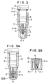
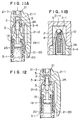
- Figs. 1A to 3B illustrate an embodiment of the writing tool of the present invention, wherein a liquid tank 1 is formed in either of a pen type or a bottle type.
- the tool comprises an extremity end 3 holding a tip 2 and loaded at an extremity part of the liquid tank .
- a cap 4 is pushed and loaded up to a part near a cap loading base end 3-1 of the extremity end 3 while being closely contacted with an outer circumference of the extremity end 3 to form a sealed space around the tip.
- an inner bottom part 4-1 of the cap 4 is abutted against a rotary member 5 projecting from the end of the tip 2 so as to cause the rotary member 5 to be retracted inwardly of the tip 2 in such a manner that the rotary member is spaced apart from an inward end seat 2-1 of the tip 2 against a spring 6.
- the end of the tip 2 is opened, and air in the cap 4 is pressurized and compressed during the pushing and loading step of the cap 4 and is fed into the liquid tank 1 whereby inner pressure of the liquid tank 1 is increased.
- an 0-ring 7 for automatically pushing back the cap 4 to a normal loaded position on of the extremity end 3 when the pushing operation on the cap 4 is released.
- the normal loaded position of the cap 4 against the extremity end 3 is when an annular projection 9 at the inner surface of the cap 4 is engaged with an annular projection 8 at the outer periphery of the extremity end 3.
- the tip 2 and the extremity end 3 are of a well-known structure. That is, the tip 2 is a pipe of metallic material, having an open edge at an end narrowed by press fitting and the like to form an inward end seat 2-1, and concurrently a radial longitudinal groove 10 arranged inside the edge is formed by.
- the rotary member 5 is held between the longitudinal groove 10 and the inward end seat 2-1 the rotary member being resiliently urged and contacted with the inward end seat 2-1 so that part is projected from the inward end seat 2-1.
- the extremity end 3 has a straight large-diameter cylindrical part 3-2 ranging from the cap loading base end 3-1 to the midway part directed toward the extremity end for holding the tip 2, the extremity end is formed into a stepped cylindrical shape of narrow end formed substantially into a narrow straight toward its end and then the tip 2 is press fitted into and held at a small-diameter cylinder part 3-3 at the extremity end.
- the cap 4 is of a stepped shape with a narrow end thereof corresponding with the outer shape of the extremity end 3, and the length LI from an opening end surface 4-2 to an inner bottom part 4-1 is so related to the length L2 from the end of the tip 2 from which the rotary member 5 is projected to a part near the cap loading base end 3-1 of the extremity end 3 such that when the cap 4 is loaded up to a part near the cap loading base end 3-1 of the extremity end 3, as shown in Fig.3, the opening end surface 4-2 of the cap 4 is abutted against the 0-ring 7 at the cap loading base end 3-1 so as to cause the 0-ring 7 to be resiliently deformed and concurrently the inner bottom part 4-1 is abutted against the rotary member 5 projected from the extremity end of the tip 2, whereby the rotary member 5 is retracted inwardly of the tip 2 against the spring 6 in such a manner that it is spaced apart from the inward end seat 2-1.
- Reference numeral 11 in the figure denotes an annular projection arranged at the inner surface of the reduced diameter part 4-3 of the cap 4 and this projection acts to be closely contacted with the outer periphery of the reduced diameter part 3-3 of the extremity end 3 during the process in which the cap 4 is pushed and loaded against the extremity end 3 so as to compress the air in the cap 4 in the sealed space around the tip 2.
- the reduced diameter part 4-1 of the cap 4 is provided with a step 12 directed from the inner bottom part 4-1 toward the opening end surface 4-1 so that when the cap 4 is loaded against the extremity end 3 to cause its inner bottom part 4-1 to abut against the rotary member 5 and further to cause the rotary member 5 to be retracted, the step is abutted against the extremity end surface 3-4 of the extremity end 2 so as to restrict the loading and the amount of movement o f the cap 4 in respect to the extremity end 3.
- the 0-ring 7 is resiliently deformed when the cap 4 is pushed into and loaded to a part near the cap loading base end 3-1 of the extremity end 3 and it pushes back the cap 4 automatically to the normal loaded position in respect to the extremity end 3 when the pushing operation is released [(a user's hand is removed from the cap 4)] and the rotary member 5 under the action of spring 6, again contacts the inward end seat 2-1 to cause the extremity end of the tip 2 to be closed.
- the 0-ring 7 is made of resilient materials, such as silicone rubber or soft resin or foamed styrol or the like capable of realizing a recovering force for pushing back the cap to the normal loaded position on the extremity end 3 .
- the 0-ring 7 is installed at the engaging groove 13 arranged at the cap loading base end 3-1.
- the 0-ring 7 may be hollow.
- the hollow space may contain air or a gel like substance in such a degree as to enable pushing back the cap 4 to the normal loaded position on the extremity end 3.
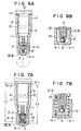
- Figs. 5A to 6B illustrate another embodiment of the writing tool of the present invention, and the only difference in this embodiment and that of Figs. 1 to 4, is that the resilient member for use in pushing back the cap 4 from the part near the cap loading base end 3-1 of the extremity end 3 to its normal loading position, is a ring-shaped leaf spring 14.
- the same reference numerals are applied to the same parts already described in relation to the embodiment of Figs. 1 to 4.
- the leaf spring 14 is of a ring-shape freely fitted to the engaging groove 15 arranged at the cap loading base end 3-1 of the extremity end 3, and it performs exactly the same function as the O ring 7.
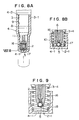
- Figs. 7A to 8B illustrate another embodiment of the writing tool of the present invention, wherein the resilient means for returning the cap is a spring 16 located and loaded in the reduced diameter part 4-3 of the cap 4 so that after the cap is pushed onto the extremity end 3 and released as described above, the cap 4 is pushed from the cap loading base end 3-1 of the extremity end 3 to the normal loaded position on of the extremity end 3 by the spring 16.
- This embodiment is basically the same as that of the detailed embodiment described above except in the length of the cap 4 itself and the arrangement of the spring 16, so that the same reference numerals are applied to the same parts to eliminate their description.
- the cap 4 is such that a length L3 thereof ranging from the opening end surface 4-2 to the inner bottom part 4-1 is related t o a length L4 ranging from the extremity end of the tip 2 to the cap insertion and loading base end 3-1 of the extremity end 3, so that when the cap 4 is pushed onto the extremity end 3 and loaded there until the opening end surface 4-2 is abutted against the cap insertion and loading base end 3-1, the inner bottom part 4-1 is abutted against the rotary member 5 projected from the extremity end of the tip 2, with the effect as already described in relation to Figs. 1 to 4
- the spring 16 is formed to have a proper length with such an outer diameter so as to be capable of being freely inserted into the reduced diameter part 4-3 of the cap 4 by a press fitting at a supporting stepped part 17 of diameter slightly smaller than the outer diameter of the spring 16 at the inner bottom part 4-1 of the reduced diameter part 4-3.
- the spring is coaxially installed within the reduced diameter part 4-3 while being projected from the reduced diameter part 4-3 toward the opening end of the cap 4.
- the supporting of one end of the spring 16 at the supporting step 17 of the reduced diameter part 4-3 is not limited to press fitting, but various means can be optionally be used such as supporting by screw thread by arranging a helical groove 18 at the inner surface of the reduced diameter part 4-3 as shown in Fig.9 to enable several turns at one end of the spring 16 to be supported.
- the writing tool of the embodiment described above operates in the same manner as that described with reference to Figs. 1 to 4.
- the writing tool of the invention as exemplified by the embodiments described above is substantially simplified as compared with that of the prior art writing tool and further enable its manufacturing cost to be reduced.
- the valve opening operation for retracting the rotary member projected out of the extremity end of the tip inwardly toward the tip so as to feed the compressed air into the liquid tank is performed in such a manner that the rotary member is abutted against the inner bottom part of the cap, so that the valve opening operation can be maintained positively and stably for a long period of time without being damaged in a short period of time as found in the prior art writing tool.
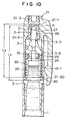
- Figs.10 to 13B illustrate another embodiment of the writing tool of the present invention, wherein the resilient means is a cylindrical resilient member 19 which performs the same function as the resilient members in the previous embodiments and is loaded at an outer periphery of the extremity end 3.
- the cap 21 is pushed and loaded up to a cap loading base end 3-1 in respect to the extremity end 3 as in the previous embodiments with a cap returning resilient part 20 arranged at an outer periphery of the cylindrical part 19-1 of the resilient member 19 and when the pushing operation is released the cap 21 is automatically pushed back to the normal loaded position of the extremity end 3.
- the cap 21 is comprised of a cap main body 21-2 and an inner cap body 21-3, and during the process in which the cap 21 is loaded in respect to the extremity end 3, the inner cap body 21-3 is closely contacted with the outer periphery of the extremity end 3 to compress the air within the inner cap body 21-3, the inner bottom surface 21-1 is contacted with the rotary member 5 projected out of the extremity end of the tip 2, the rotary member 5 is spaced apart from the inward end seat 2-1 of the tip 2 against a spring 6 so as to open the valve structure at the end of the tip 2.
- This embodiment is basically the same as the detailed embodiment described above other in the form of the resilient member 19 for use in returning the cap 21 and the cap 21 are changed. The same reference numerals are applied to the same and their description will be eliminated.
- the extremity end 3 is composed of a large diameter cylindrical part 3-2 having a straight segment ranging from the cap loading base end 3-1 toward the midway part of extremity end holding the tip 2, as described in detail in reference to the aforesaid embodiment .
- the tip 2 is held by being press fitted to the reduced diameter cylindrical part 3-3 of the extremity end.
- An outer periphery of the large diameter cylindrical part 3-2 of the extremity end 3 is provided with an indent part 22 so as to enable the resilient member 19 to be loaded flush with the outer periphery of the large diameter cylindrical part 3-2.
- the indent part 22 is formed in compliance with the thickness of a cylindrical wall of the cylindrical part 19-1 of the resilient member 19 over a length from the cap loading base end 3-1 to the substantial full length of the large diameter cylindrical part 3-2.
- An annular groove 23 having a proper width and depth is arranged along an opening edge at the bottom part of the indent part 22 located at the reduced diameter cylindrical part 3-3, and an annular projection 24 of the resilient member 19 to be described later is formed to be engaged in the groove 23 through a fastening action.
- the cap 21 is comprised of a cap main body 21-2; and an inner cap body 21-3 which is coaxially assembled at a tail end of the cap main body 21-2.
- the inner cap body 21-3 is installed internally of the main body, and_ sealingly contacts the outer periphery of the reduced diameter cylindrical part 3-3 of the extremity end 3 when the cap main body 21-2 is loaded at the extremity end 3, thereby sealingly closing the tip 2 which projects from the reduced diameter cylindrical part 3-3.
- the cap main body 21-2 is made of transparent synthetic resin material and has a cylindrical shape having an inner diameter which is larger about twice that of the large diameter cylindrical part 3-2 of the extremity end 3.
- the cap main body 21-2 covers the extremity end 3 in one state in which there is a clearance 25 between it and the outer periphery of the large diameter cylindrical part 3-2 of the extremity end 3 to cause inner air to be naturally retracted during loading of the cap in respect to the extremity end 3.
- a length L5 ranging from the opening end surface 2 1-20 to the inner bottom part 21-1 of the inner cap 21-3 is formed to be about a length L6 ranging from the extremity end of the tip 2 from which the rotary member 5 projects to a part near the cap loading base end 3-1 of the extremity end 3.
- the inner cap body 21-3 is formed of colored synthetic resin material and made into a cylindrical shape having a bottom part with an inner diameter closely contacted with an outer periphery of the reduced diameter cylindrical part 3-3 of the extremity end 3.
- the inner surface directed inwardly from the opening edge is formed with a stepped part 26 which abuts against the extremity end surface 3-4 of the reduced diameter cylindrical part 3-3 during the loading step in respect to the extremity end 3 so as to restrict the loading and amount of movement of the cap 21 in respect to the extremity end 3.
- the inner cap body 21-3 is coaxially assembled and internally arranged at the tail end under a fixed state in which it is fitted and engaged with an installing port 27 opened coaxially at the tail end of the cap main body 21-1.
- the cap 21 sealingly closes the tip 2, pressurizes the inner air, and retracts the rotary member 5 inwardly into the tip 2 so as to move the rotary member apart from the inward extremity edge 2-1 for feeding the compressed air into the liquid tank 1, the colored inner cap body 21-3 acting to open the valve structure located at the end of the tip 2.
- the stepped part 26 abut s against the extremity end surface 3-4 of the reduced diameter cylindrical part 3-3 of the extremity end 3 when the valve structure located at the extremity end of the tip 2 is opened so as to restrict a loading and amount of movement_ of the cap 21 in respect to the extremity end 3.
- the compressed air within the inner cap body 21-3 is positively fed from the clearance between the rotary member 5 and the inward end seat 2-1 into the liquid tank 1 [( refer to Fig. 13B)].
- the cylindrical part 19-1 may provide a means for gripping during use of the writing tool to correct wrongly written letters.
- the cap returning resilient part 20 is resiliently deformed while being pushed by the opening end surface 21-20 of the cap 21 during a loading step in respect to the extremity end 3 It recovers when the pushing operation is released [(the hand is moved away from the cap 21)] so as to act to push back the cap 21 automatically to the normal loaded position in respect to the extremity end 3 as described hereinbefore.
- the inner cap body 21-3 under its close contacted state with an outer periphery of the reduced diameter cylindrical part 3-3 of the extremity end 3 [(a state shown in Fig. 11A)], is pushed until the opening end surface 21-20 of the cap 21 is abutted against the cap returning resilient part 20 of the resilient member 19 which is abutted against the cap loading base end 3-1 [(a state shown in Fig. 12)].
- the air in the inner cap 21-3 is pressurized and compressed, and passes through a clearance 2 and the air is automatically discharged into the surrounding air [(refer to Fig. 11A)]. Accordingly, during the loading step against the extremity end 3, it is possible to load the cap 21 without there being load resistance caused by air remaining in the cap main body 21-2. That is, it is possible to load the cap 21 only with a low force.
- the opening end surface 21-20 of the cap 21 is abutted against the cap returning resilient part 20 and further pushed.
- the cap returning resilient part 20 is resiliently deformed and concurrently, the inner bottom part 21-1 of the inner cap body 21-3 is abutted against the rotary member 5 with the same effect as described hereinbefore.
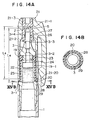
- Figs. 14A to 15B illustrate other embodiments of the writing tool of the present invention.
- Figs. 14A and 14B The only difference between the embodiment of Figs. 14A and 14B and that of Figs. 10 to 13, is that it is provided with an indent recess 29 for providing a deformed space 28 in the cap returning resilient part 20 adjacent the cap loading base end 3-1 .
- the cap returning resilient part 20 When deformation of the part 20 takes place as described herein in relation to the previous embodiment, the cap returning resilient part 20 is resiliently deformed in such a manner that the cap returning resilient part 20 is released into the deformation space 28, then as the pushing operation is released, the recovering force of the cap returning resilient part 20 is augmented by the compressed air within the compressed and deformed space.
- Figs. 15A and 15B are virtually identical to that of Figs. 14A and 14B, and will not be described in any detail other than to say that the only difference is that the indent recess 29 is formed into a substantial L-shaped section opened from the annular end surface of the cap returning resilient part 20 abutted against the cap loading base end 3-1 toward the inner surface of the cylindrical part 19-1, and the deformed space 28 is kept between the cap loading base end 3-1 of the extremity end 3 and its outer circumference, so-called bottom part of the indent 22.
- the operation is the same as the Figs. 14A and 14B embodiment.
- an ornamental effect of the cap 21 can be improved.
- the valve opening operation is performed by the inner bottom part of the cap, the operation for opening the valve can be carried out positively and stably for a long period of time. Accordingly, the writing tool of the present invention is preferable to the writing tool of the prior art.
- the tool according to the invention is useful as a tool for coating correcting fluid and so on in that correcting fluid filled in the liquid tank is fed into writing portion of the extremity end of the tip by increased internal pressure of the tank during the writing step.
Landscapes
- Engineering & Computer Science (AREA)
- Mechanical Engineering (AREA)
- Pens And Brushes (AREA)
- Coating Apparatus (AREA)
- Mechanical Pencils And Projecting And Retracting Systems Therefor, And Multi-System Writing Instruments (AREA)
Description
Claims (7)
- A writing tool comprising a liquid tank (1) having an extremity end (3), a tip (2) held in the extremity end (3), a rotary member (5) held in an end of the tip (2) in such a manner that it is resiliently urged by spring (6) to contact an inward end seat (2-1) of the tip (2) whilst a part of the rotary member (5) projects from the tip (2), and a cap (4) which can be pushed into the extremity end (3) to from a sealed space around the tip (2),
Characterized in that the length of the cap (4) from an open end surface (4-2) to an inner bottom surface (4-1) is so related to the length of the extremity end (3) from the end of the tip (2) to a cap loading base end (3-1) of the extremity end (3), whereby pushing of the cap further on to the extremity end (3) from a normal loaded position causes the bottom surface (4-1) to engage the rotary member (5) and to unseat it from the inward end seat (2-1) of the tip (2) and simultaneously cause air from the sealed space to be pumped past the rotary member (5) into the liquid tank (1) through the extremity end (3), and the cap to be pushed onto an outer periphery of the cap loading base end (3-1) of the extremity end (3), and including a resilient member (7, 16, 19) which pushes back the cap (4) to the normal loaded position on the extremity end (3) when the pushing force is released, so that the rotary member re-seats on the inward end seat. - A writing tool as set forth in Claim 1, wherein the resilient member is an 0-ring (7) which is resiliently deformed when the cap 4 is pushed onto the cap loading base end (3-1) of the extremity end (3)
- A writing tool as set forth in Claim 1, wherein the resilient member is a leaf spring (14) which is resiliently deformed when the cap (4) is pushed onto the cap loading base end (3-1) of the extremity end (3).
- A writing tool as set forth in Claim 1, wherein the resilient member is a spring (16).
- A writing tool as set forth in claim 1, wherein the resilient member (19) is cylindrical and extends from the cap loading base end (3-1) of said extremity end (3) toward the tip (2) and is provided with an annular cap returning resilient part (20) projecting in a circumferential direction along one end (19-1) of the cylindrical member (19) and is abutted against the cap loading base end (3-1).
- A writing tool as set forth in Claim 1, wherein the cap (21) comprises a transparent cap main body (21-2) having an inner diameter about twice the outer diameter of the extremity end (3), and a colored cylindrical inner cap body (21-3) with a bottom which is coaxial with a tail end of the cap main body (21-2), said inner cap body (21-3) closely contacting the outer periphery of the extremity end (3) and its inner bottom part (21-1) engaging the rotating member (5) when the cap (4) is pushed from the normal loaded position.
- A writing tool as set forth in Claim 5, wherein an annular end surface of at least the cap returning resilient part (20) is provided with an indent recess (29) at the cap loading base end (3-1) for augmenting resilient action of the cap returning resilient part (20).
Applications Claiming Priority (7)
| Application Number | Priority Date | Filing Date | Title |
|---|---|---|---|
| JP07866295A JP3645612B2 (en) | 1995-04-04 | 1995-04-04 | Writing instrument |
| JP7866295 | 1995-04-04 | ||
| JP78662/95 | 1995-04-04 | ||
| JP22184495 | 1995-08-30 | ||
| JP221844/95 | 1995-08-30 | ||
| JP22184495 | 1995-08-30 | ||
| PCT/JP1996/000923 WO1996031354A1 (en) | 1995-04-04 | 1996-04-04 | Writing utensil |
Publications (3)
| Publication Number | Publication Date |
|---|---|
| EP0823337A1 EP0823337A1 (en) | 1998-02-11 |
| EP0823337A4 EP0823337A4 (en) | 1999-05-19 |
| EP0823337B1 true EP0823337B1 (en) | 2003-03-12 |
Family
ID=26419714
Family Applications (1)
| Application Number | Title | Priority Date | Filing Date |
|---|---|---|---|
| EP96908341A Expired - Lifetime EP0823337B1 (en) | 1995-04-04 | 1996-04-04 | Writing utensil |
Country Status (6)
| Country | Link |
|---|---|
| US (1) | US5888009A (en) |
| EP (1) | EP0823337B1 (en) |
| DE (1) | DE69626640D1 (en) |
| MY (1) | MY123752A (en) |
| TW (1) | TW317818U (en) |
| WO (1) | WO1996031354A1 (en) |
Families Citing this family (8)
| Publication number | Priority date | Publication date | Assignee | Title |
|---|---|---|---|---|
| USD418870S (en) * | 1999-02-24 | 2000-01-11 | The Gillette Company | Writing instrument with a cap |
| US6446549B1 (en) * | 2000-11-16 | 2002-09-10 | Carla B. Soucie | Hand-held paper embossing tool |
| US6637966B2 (en) * | 2001-04-06 | 2003-10-28 | Keith Roberts | Sealable toiletry article |
| US20090142128A1 (en) * | 2007-11-29 | 2009-06-04 | Kurtis Johnson | Dry erase marker renewal device |
| JP2017154444A (en) * | 2016-03-03 | 2017-09-07 | 三菱鉛筆株式会社 | Thermochromic writing instrument |
| CN105751743A (en) * | 2016-05-12 | 2016-07-13 | 冯文达 | Elastic full-needle-tube ball pen head |
| KR102767749B1 (en) * | 2018-08-29 | 2025-02-17 | 미쓰비시 엔피쯔 가부시키가이샤 | Writing instrument with refill |
| US11259624B2 (en) * | 2019-10-30 | 2022-03-01 | Masoud Tabesh Nekoo | Paint applicator with brush |
Family Cites Families (7)
| Publication number | Priority date | Publication date | Assignee | Title |
|---|---|---|---|---|
| JPS61270196A (en) * | 1985-05-27 | 1986-11-29 | パイロツトインキ株式会社 | Cap for writing utensil |
| JPS6222883U (en) * | 1985-07-25 | 1987-02-12 | ||
| JPS63154284U (en) * | 1987-03-31 | 1988-10-11 | ||
| US5362169A (en) * | 1992-10-30 | 1994-11-08 | Sailor Pen Co., Ltd. | Applicator having cap which pressurizes inner space |
| JP2528774Y2 (en) * | 1992-10-30 | 1997-03-12 | セーラー万年筆株式会社 | Applicator |
| JP2528773Y2 (en) * | 1992-10-30 | 1997-03-12 | セーラー万年筆株式会社 | Applicator |
| JP2566664Y2 (en) * | 1993-08-31 | 1998-03-30 | セーラー万年筆株式会社 | Applicator |
-
1996
- 1996-03-20 TW TW085217239U patent/TW317818U/en unknown
- 1996-03-28 MY MYPI96001154A patent/MY123752A/en unknown
- 1996-04-04 EP EP96908341A patent/EP0823337B1/en not_active Expired - Lifetime
- 1996-04-04 DE DE69626640T patent/DE69626640D1/en not_active Expired - Lifetime
- 1996-04-04 WO PCT/JP1996/000923 patent/WO1996031354A1/en not_active Ceased
- 1996-04-04 US US08/930,251 patent/US5888009A/en not_active Expired - Fee Related
Also Published As
| Publication number | Publication date |
|---|---|
| MY123752A (en) | 2006-06-30 |
| US5888009A (en) | 1999-03-30 |
| TW317818U (en) | 1997-10-11 |
| EP0823337A1 (en) | 1998-02-11 |
| DE69626640D1 (en) | 2003-04-17 |
| WO1996031354A1 (en) | 1996-10-10 |
| EP0823337A4 (en) | 1999-05-19 |
Similar Documents
| Publication | Publication Date | Title |
|---|---|---|
| AU2003230963B2 (en) | Self-sealing retractable writing instrument | |
| US20090136284A1 (en) | Slide Type Writing Tools Having Device for Prevent Dryness | |
| EP1396210B1 (en) | Liquid container | |
| US4575271A (en) | Writing instrument with movable closure and second sealing means | |
| US6729787B2 (en) | Applicator using pressurized air to aid in dispensing liquid | |
| US7341388B2 (en) | Retractable writing instruments with volatile inks | |
| US5888009A (en) | Writing tool and pressurizing cap | |
| EP2567829A1 (en) | Pressurizing type pen | |
| JP3797426B2 (en) | Applicator | |
| EP0621141B1 (en) | Applicator | |
| US5092702A (en) | Fluid discharge device | |
| JP2002264579A (en) | Capless writing instrument | |
| US5462379A (en) | Applicator having cap which pressurizes and seals inner space | |
| US20050084321A1 (en) | Retractable vacuum reservoir applicator and writing tool with self sealing valve | |
| US20050074268A1 (en) | Drawing or writing utensil and casing or protective sleeve | |
| HK1002954A (en) | Writing utensil | |
| CN109419133B (en) | Cosmetic container | |
| US6220774B1 (en) | Ballpoint tip for ballpoint liquid container | |
| US5542771A (en) | Applicator having cap which pressurizes and seals inner space | |
| JP3645612B2 (en) | Writing instrument | |
| JP3601867B2 (en) | Applicator | |
| JP2004025763A (en) | Applicator | |
| JPH08266990A (en) | Applicator | |
| JP3109019B2 (en) | Correcting tool using ball or tip in writing ballpoint pen | |
| JP2001171292A (en) | Liquid formation-applicator |
Legal Events
| Date | Code | Title | Description |
|---|---|---|---|
| PUAI | Public reference made under article 153(3) epc to a published international application that has entered the european phase |
Free format text: ORIGINAL CODE: 0009012 |
|
| 17P | Request for examination filed |
Effective date: 19971004 |
|
| AK | Designated contracting states |
Kind code of ref document: A1 Designated state(s): DE FR GB IT |
|
| A4 | Supplementary search report drawn up and despatched |
Effective date: 19990407 |
|
| AK | Designated contracting states |
Kind code of ref document: A4 Designated state(s): DE FR GB IT |
|
| 17Q | First examination report despatched |
Effective date: 20000928 |
|
| GRAH | Despatch of communication of intention to grant a patent |
Free format text: ORIGINAL CODE: EPIDOS IGRA |
|
| GRAH | Despatch of communication of intention to grant a patent |
Free format text: ORIGINAL CODE: EPIDOS IGRA |
|
| GRAA | (expected) grant |
Free format text: ORIGINAL CODE: 0009210 |
|
| AK | Designated contracting states |
Designated state(s): DE FR GB IT |
|
| PG25 | Lapsed in a contracting state [announced via postgrant information from national office to epo] |
Ref country code: IT Free format text: LAPSE BECAUSE OF FAILURE TO SUBMIT A TRANSLATION OF THE DESCRIPTION OR TO PAY THE FEE WITHIN THE PRE;WARNING: LAPSES OF ITALIAN PATENTS WITH EFFECTIVE DATE BEFORE 2007 MAY HAVE OCCURRED AT ANY TIME BEFORE 2007. THE CORRECT EFFECTIVE DATE MAY BE DIFFERENT FROM THE ONE RECORDED.SCRIBED TIME-LIMIT Effective date: 20030312 Ref country code: FR Free format text: LAPSE BECAUSE OF FAILURE TO SUBMIT A TRANSLATION OF THE DESCRIPTION OR TO PAY THE FEE WITHIN THE PRESCRIBED TIME-LIMIT Effective date: 20030312 |
|
| REG | Reference to a national code |
Ref country code: GB Ref legal event code: FG4D |
|
| PGFP | Annual fee paid to national office [announced via postgrant information from national office to epo] |
Ref country code: GB Payment date: 20030331 Year of fee payment: 8 |
|
| REF | Corresponds to: |
Ref document number: 69626640 Country of ref document: DE Date of ref document: 20030417 Kind code of ref document: P |
|
| PG25 | Lapsed in a contracting state [announced via postgrant information from national office to epo] |
Ref country code: DE Free format text: LAPSE BECAUSE OF FAILURE TO SUBMIT A TRANSLATION OF THE DESCRIPTION OR TO PAY THE FEE WITHIN THE PRESCRIBED TIME-LIMIT Effective date: 20030613 |
|
| PLBE | No opposition filed within time limit |
Free format text: ORIGINAL CODE: 0009261 |
|
| STAA | Information on the status of an ep patent application or granted ep patent |
Free format text: STATUS: NO OPPOSITION FILED WITHIN TIME LIMIT |
|
| EN | Fr: translation not filed | ||
| 26N | No opposition filed |
Effective date: 20031215 |
|
| PG25 | Lapsed in a contracting state [announced via postgrant information from national office to epo] |
Ref country code: GB Free format text: LAPSE BECAUSE OF NON-PAYMENT OF DUE FEES Effective date: 20040404 |
|
| REG | Reference to a national code |
Ref country code: HK Ref legal event code: WD Ref document number: 1002954 Country of ref document: HK |
|
| GBPC | Gb: european patent ceased through non-payment of renewal fee |