EP0823142B1 - Temperature regulating laser diode assembly - Google Patents
Temperature regulating laser diode assembly Download PDFInfo
- Publication number
- EP0823142B1 EP0823142B1 EP96913060A EP96913060A EP0823142B1 EP 0823142 B1 EP0823142 B1 EP 0823142B1 EP 96913060 A EP96913060 A EP 96913060A EP 96913060 A EP96913060 A EP 96913060A EP 0823142 B1 EP0823142 B1 EP 0823142B1
- Authority
- EP
- European Patent Office
- Prior art keywords
- laser diode
- thermoelectric cooler
- assembly
- heat
- window
- Prior art date
- Legal status (The legal status is an assumption and is not a legal conclusion. Google has not performed a legal analysis and makes no representation as to the accuracy of the status listed.)
- Expired - Lifetime
Links
Images


Classifications
-
- H—ELECTRICITY
- H01—ELECTRIC ELEMENTS
- H01L—SEMICONDUCTOR DEVICES NOT COVERED BY CLASS H10
- H01L33/00—Semiconductor devices with at least one potential-jump barrier or surface barrier specially adapted for light emission; Processes or apparatus specially adapted for the manufacture or treatment thereof or of parts thereof; Details thereof
- H01L33/48—Semiconductor devices with at least one potential-jump barrier or surface barrier specially adapted for light emission; Processes or apparatus specially adapted for the manufacture or treatment thereof or of parts thereof; Details thereof characterised by the semiconductor body packages
- H01L33/64—Heat extraction or cooling elements
- H01L33/645—Heat extraction or cooling elements the elements being electrically controlled, e.g. Peltier elements
-
- H—ELECTRICITY
- H01—ELECTRIC ELEMENTS
- H01S—DEVICES USING THE PROCESS OF LIGHT AMPLIFICATION BY STIMULATED EMISSION OF RADIATION [LASER] TO AMPLIFY OR GENERATE LIGHT; DEVICES USING STIMULATED EMISSION OF ELECTROMAGNETIC RADIATION IN WAVE RANGES OTHER THAN OPTICAL
- H01S5/00—Semiconductor lasers
- H01S5/02—Structural details or components not essential to laser action
- H01S5/024—Arrangements for thermal management
- H01S5/02407—Active cooling, e.g. the laser temperature is controlled by a thermo-electric cooler or water cooling
- H01S5/02415—Active cooling, e.g. the laser temperature is controlled by a thermo-electric cooler or water cooling by using a thermo-electric cooler [TEC], e.g. Peltier element
Definitions
- This invention relates generally to laser diode assemblies. More specifically, it pertains to a temperature regulating laser diode assembly having a thermoelectric cooling unit for permitting operation of the laser diode in harsh environmental conditions.
- Laser diodes have become preferred electronic components for applications requiring an inexpensive source of coherent light.
- Laser diodes otherwise known as semiconductor lasers, are ideal for highly accurate optical information collection, transmission and processing.
- the variety of uses for laser diodes has greatly expanded. Once used solely for scientific and research applications, laser diodes are now employed in many commercial and consumer products.
- the bar code scanner identification industry uses laser diodes in many applications that require small, low-power laser scanners. Scanners using laser diodes are smaller, lighter and draw less power than helium-neon based laser scanners, which were previously the most commonly used type of laser scanner. As laser diode scanners have become more popular, they have been used in a variety of wide-ranging scanning applications including point-of-sale checkout terminals, assembly and production line tracking systems, and warehouse storage systems.
- laser diode scanners may be subject to harsh environmental conditions that are less than ideal for electronic components, including high temperature and high humidity environments. Operating a laser diode at elevated temperatures for extended periods of time decreases the expected operating life of the component, thereby increasing maintenance costs and associated down-time of the scanning system.
- thermoelectric coolers to remove heat from a laser diode, thereby reducing the temperature and preventing thermal degradation of the diode.
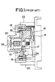
- a typical scanning device which employs a laser diode and a thermoelectric cooler is shown in Figure 1 .
- This system includes a laser diode 10 which is mounted on a retainer plate 12. The plate 12 is supported by a thermally conductive spacer 14 which is coupled to a thermoelectric cooler 16 .
- a thermally conductive flange 18 holds an optical assembly 20 in a supported relationship with the diode 10 via two screws 19 . Since the optical assembly 20 and the laser diode 10 are coupled by thermally conductive materials, they are maintained at the same temperature.
- a thermistor 24 detects the temperature of the spacer 14 and regulates the thermoelectric cooler 16 to keep the optical assembly 20 and laser diode 10 at a desired operating temperature.
- the laser diode 10 and the optical assembly 20 are hermetically sealed in a thermally insulated housing 22 , which has an optically transparent window 26 for permitting the laser beam to exit.
- condensation may form on the laser diode window.
- a small heating element may be used to heat the window and prevent the formation of condensation, this further reduces the efficiency and increases the size of the scanning system.
- a laser diode unit as disclosed in JP,A, 58-187 961 includes a laser diode package coupled with a Peltier element for cooling the laser diode package.
- the laser diode unit is located within a cavity in the Peltier element. Condensation is prevented from forming on the window of laser diode package by the heat emitting side of the Peltier element which heats the air generally surrounding the window. However, heating of the air surrounding the window does not provide adequate control for heating of the window. Additionally, since the laser diode package is not mechanically coupled with the optics, mechanical vibration or shocks may misalign the optics and the laser diode package.
- the temperature regulated laser diode assembly of the invention comprises the features of claim 1.
- a preferred embodiment of the present invention comprises an improved laser diode assembly including a laser diode unit which is mounted directly on a compact thermoelectric cooler.
- the thermoelectric cooler is mounted on a male heat sink, which is coupled to a female heat sink.
- a thermally insulating gasket mounted around the thermoelectric cooler and between the male and female heat sinks, seals the thermoelectric cooler from the ambient environment, thereby preventing condensation from forming on the cold face of the thermoelectric cooler.
- a Delrin® bushing concentrically positions the laser diode unit in the proper optical path with respect to the optical assembly, while thermally and electrically insulating the laser diode from the heat sinks and all other external metallic components.
- the laser diode is less susceptible to electrostatic discharge, which may cause damage to the diode.
- a thermally conductive gasket mounted around the circumference of the laser diode window, returns a portion of the heat from the heat sinks to the window to prevent condensation from forming on the window.
- the laser diode is the only component cooled by the thermoelectric cooler. Accordingly, reduced thermoelectric cooler size and more efficient operation of the laser diode assembly is achieved. Since a portion of the heat transferred by the thermoelectric cooler is utilized to warm the laser diode window, a separate heating element is not required. This increases the overall efficiency of the laser diode assembly.
- the laser diode assembly 50 comprises a laser diode unit 52 mounted on a thermoelectric cooler semiconductor chip (TE cooler) 54 .
- the laser diode unit 52 comprises two sections; a cylindrically-shaped housing or "can" portion and a substantially flat base or "flange” portion.
- the laser diode semiconductor substrate, which generates the laser beam, is thermally coupled to the flange.
- the substrate may be mounted directly on the flange, which provides heat sinking for the substrate. This provides a highly conductive thermal path for removing heat from the substrate.
- the can portion includes an aperture which typically has an optically transparent window 56 through which the laser beam emanates.
- the can is welded to the flange to hermetically seal the laser diode unit 52 . Since the laser diode substrate is thermally coupled to the flange, most of the heat generated by the substrate is removed from the flange rather than the can.
- the size and power of the laser diode unit 52 depends upon the particular application for which the laser diode assembly 50 will be used.
- the laser diode unit 52 is a Toshiba Model No. TOLD9215(S).
- the technical specifications of the laser diode unit 52 are shown in Table 1.
- the heat transferring capacity of the TE cooler 54 depends upon the power of the laser diode unit 52 selected.
- the TE cooler 54 is a Melcor, Corporation Model No. SHO.8-28-05L.
- the technical specifications of the TE cooler 54 are shown in Table 2 , THERMOELECTRIC COOLER CHARACTERISTIC MAXIMUM RATINGS Current 2,6 A Power 4,9 W Voltage 3,4 V Temperature Difference ( ⁇ Tmax) 67°C
- the TE cooler 54 is mounted upon a male heat sink 58 .
- thermally conductive tape 60 is used to couple the laser diode unit 52 to the TE cooler 54 , and the TE cooler 54 to the male heat sink 58 .
- the thermally conductive tape 60 adhesively bonds the three components 52, 54, 58 together and provides thermal conductivity therebetween.
- a female heat sink 62 is frictionally coupled to the male heat sink 58 .
- a thermal gasket 64 surrounds the interface between the cold and hot faces of the TE cooler 54 , and fills the interior chamber created by the male heat sink 58 and the female heat sink 62 . The gasket 64 seals the TE cooler 54 from the ambient environment.
- the gasket 64 also stabilizes the temperature of the interior chamber.
- the gasket 64 is made of closed-cell foam, manufactured by Stockwell Rubber Co.
- a bushing 66 having an inner diameter (or pilot diameter) which is sized to fit around the laser diode unit 52 and an outer diameter (or boss diameter) sized to engage and concentrically position the laser diode unit 52 in the proper optical path with respect to a telescopic optical assembly 80 .
- the bushing 66 made from a polymer, preferably Delrin®, also provides electrical and thermal isolation of the laser diode 52 from the male and female heat sinks 58, 62 and any other external metallic components. This makes the laser diode 52 less vulnerable to damage caused by electrostatic discharge.
- a printed circuit (PC) board 68 mounted directly to the male heat sink 58 by two socket head cap screws 70 supports driver circuitry for the laser diode unit 52 and the TE cooler 54 .
- the screws 70 extend through the driver board 68 , the male heat sink 58 , the thermal gasket 64 , and the female heat sink 62 to a barrel 82 which is part of the telescopic optical assembly 80 . Accordingly, the entire laser diode assembly 50 is securely fastened as a unitary structure by the two screws 70.
- a thermistor 108 (shown in Figure 3 ) is mounted on the side of the PC board 68 facing the laser diode unit 52 .
- the thermistor 108 touches the center of the flange between the leads of the laser diode unit 52 to directly monitor the temperature of the flange.
- the PC board 68 also includes all of the electronic components for controlling the operation of the laser diode unit 52 and the TE cooler 54 . External electrical connections to the PC board 68 are made via a multi-pin connector. As will be appreciated by those skilled in the art, a detailed description of each electronic component is outside the scope of this invention.
- the telescopic optical assembly 80 comprises a barrel 82 which is threadably coupled to one or more lens assemblies 84 , 85 and held by a clamp collar 86 .
- the optical assembly collimates and focuses the laser beam 100 .
- the clamp collar 86 comprises a split ring having two complimentary sections which are fastened together with socket head cap screws 88 .
- the clamp collar 86 frictionally clamps the barrel 82 onto the bar code scanner.
- the collar 86 made of aluminum, is an extension of the male and female heat sinks 58, 62 .
- the female heat sink 62 makes full contact with the face of both sections of the collar 86.
- thermally conductive grease is applied between the interfacing surfaces of the female heat sink 62 and the clamp collar 86.
- a thermally conductive laser diode washer 92 is disposed between the barrel 82 and the laser diode 52 .
- the washer 92 is configured in an "flat ring" shape with an inner diameter complimenting the circumference of the laser diode window 56 and an outer diameter sized to fit within the barrel 82. Accordingly, the washer 92 conducts heat from the barrel 82 to the top of the can directly around the laser diode window 56.
- the washer 92 is electrically non-conductive, thereby preventing an electrostatic discharge introduced to the laser diode assembly 50 from damaging the laser diode unit 52.
- the washer is a thermally conductive silicone sponge, part # R10404, manufactured by Stockwell Rubber Co. The sponge material accommodates different laser diode can heights and assures positive conductive contact when assembling the laser diode assembly 50 , without crushing the can or cracking the laser diode window 56.
- the operation of the preferred embodiment of the present invention will be explained with reference to Figure 3 .
- a beam of light 100 is emitted.
- a portion of the power applied to the laser diode unit 52 is converted to heat since the laser diode 52 is not 100% efficient.
- the TE cooler 54 is provided to transfer the heat away from the laser diode unit 52 and to keep the laser diode unit 52 at the desired operating temperature.
- thermoelectric cooler is essentially an electronic heat pump which uses the Peltier effect to transfer heat from one face of the cooler to the other.
- heat is transferred from the cold face 102 to the hot face 104. Accordingly, one face of the TE cooler 54 is "cool” and the other side is “warm”. Since the laser diode unit 52 is coupled to the cold face 102 of the TE cooler 54 , the heat generated by the laser diode unit 52 is transferred by the TE cooler 54 to the hot face 104 and then to the male heat sink 58. The heat is further conducted by the male heat sink 58 to the female heat sink 62, the barrel 82 and the clamp collar 86 .
- the lens assemblies 84, 85 are not significantly warmed since the interface between lens assembly 84 and the barrel 82 is a poor thermal conductor. This interface primarily comprises air gaps and a barrel thread lubricant.
- the barrel 82 conducts a portion of the heat from the female heat sink 62 to the laser diode 52 via the thermally conductive laser diode washer 92 .
- the washer 92 is located about the periphery of the laser diode window 56 to conduct heat to the window 56 thereby preventing condensation from forming on the window 56 .
- FIG. 4 An alternative embodiment of the invention is shown in Figure 4 .
- the thermally conductive washer 92 and the Delrin® bushing 66 have been eliminated.
- the female heat sink 62 is configured to contact the top of the can around the periphery of the window 56. Accordingly, the female heat sink 62 conducts heat directly to the top of the can.
- a thermally conductive and electrically insulating washer may be placed between the female heat sink 62 and the top of the can. This would provide the thermal conduction required while preventing electrostatic discharges from damaging the laser diode unit 52.
- a thermostatic control circuit located on the PC board 68 monitors the thermistor 108 , which detects the temperature of the flange to ensure that the laser diode unit 52 is operating at the preferred temperature.
- the TE cooler 54 is turned on.
- the TE cooler 54 is turned off.
- the set point for the thermostatic control circuit is 33°C.
- the laser diode unit 52 is the only component being cooled.
- the laser diode 52 can be maintained at a temperature of 33°C while ambient temperature is 50°C. Additionally, since the can will be warmed as the flange is cooled by the TE cooler 54 there is no need for separate cooling and heating components.
- the assembly 50 can operate in environments of up to 90% relative humidity without condensation forming on any optical surfaces.
Abstract
Description
- This invention relates generally to laser diode assemblies. More specifically, it pertains to a temperature regulating laser diode assembly having a thermoelectric cooling unit for permitting operation of the laser diode in harsh environmental conditions.
- Laser diodes have become preferred electronic components for applications requiring an inexpensive source of coherent light. Laser diodes, otherwise known as semiconductor lasers, are ideal for highly accurate optical information collection, transmission and processing. As the power and efficiency of laser diodes have increased, the variety of uses for laser diodes has greatly expanded. Once used solely for scientific and research applications, laser diodes are now employed in many commercial and consumer products.
- The bar code scanner identification industry, in particular, uses laser diodes in many applications that require small, low-power laser scanners. Scanners using laser diodes are smaller, lighter and draw less power than helium-neon based laser scanners, which were previously the most commonly used type of laser scanner. As laser diode scanners have become more popular, they have been used in a variety of wide-ranging scanning applications including point-of-sale checkout terminals, assembly and production line tracking systems, and warehouse storage systems.
- Depending upon the particular application, laser diode scanners may be subject to harsh environmental conditions that are less than ideal for electronic components, including high temperature and high humidity environments. Operating a laser diode at elevated temperatures for extended periods of time decreases the expected operating life of the component, thereby increasing maintenance costs and associated down-time of the scanning system.
- Present scanning systems utilize thermoelectric coolers to remove heat from a laser diode, thereby reducing the temperature and preventing thermal degradation of the diode. A typical scanning device which employs a laser diode and a thermoelectric cooler is shown in Figure 1. This system includes a
laser diode 10 which is mounted on aretainer plate 12. Theplate 12 is supported by a thermallyconductive spacer 14 which is coupled to athermoelectric cooler 16. A thermallyconductive flange 18 holds anoptical assembly 20 in a supported relationship with thediode 10 via twoscrews 19. Since theoptical assembly 20 and thelaser diode 10 are coupled by thermally conductive materials, they are maintained at the same temperature. Athermistor 24 detects the temperature of thespacer 14 and regulates thethermoelectric cooler 16 to keep theoptical assembly 20 andlaser diode 10 at a desired operating temperature. Thelaser diode 10 and theoptical assembly 20 are hermetically sealed in a thermally insulatedhousing 22, which has an opticallytransparent window 26 for permitting the laser beam to exit. - Although present assemblies compensate for high ambient temperatures, they require coolers with sufficient capacity to cool the entire assembly. Additionally, these systems require complete thermal isolation of internal electronic components from the ambient environment, resulting in scanning systems that are bulky and inefficient.
- When a laser diode is cooled below the temperature of the ambient environment, condensation may form on the laser diode window. Although a small heating element may be used to heat the window and prevent the formation of condensation, this further reduces the efficiency and increases the size of the scanning system.
- A laser diode unit as disclosed in JP,A, 58-187 961 includes a laser diode package coupled with a Peltier element for cooling the laser diode package. The laser diode unit is located within a cavity in the Peltier element. Condensation is prevented from forming on the window of laser diode package by the heat emitting side of the Peltier element which heats the air generally surrounding the window. However, heating of the air surrounding the window does not provide adequate control for heating of the window. Additionally, since the laser diode package is not mechanically coupled with the optics, mechanical vibration or shocks may misalign the optics and the laser diode package.
- It is a primary object of the present invention to provide a laser diode assembly that efficiently maintains the laser diode at the recommended operating temperature while preventing condensation from forming on the laser diode window.
- It is a further object of the present invention to provide an efficient laser diode assembly which can operate in adverse temperature and humidity environments without decreasing the operating life of the laser diode.
- It is a further object of the invention to provide a laser diode assembly which maintains each part of the laser diode at the desired operating temperature.
- To achieve this, the temperature regulated laser diode assembly of the invention comprises the features of claim 1.
- A preferred embodiment of the present invention comprises an improved laser diode assembly including a laser diode unit which is mounted directly on a compact thermoelectric cooler. The thermoelectric cooler is mounted on a male heat sink, which is coupled to a female heat sink. A thermally insulating gasket, mounted around the thermoelectric cooler and between the male and female heat sinks, seals the thermoelectric cooler from the ambient environment, thereby preventing condensation from forming on the cold face of the thermoelectric cooler. A Delrin® bushing concentrically positions the laser diode unit in the proper optical path with respect to the optical assembly, while thermally and electrically insulating the laser diode from the heat sinks and all other external metallic components. Thus, the laser diode is less susceptible to electrostatic discharge, which may cause damage to the diode. A thermally conductive gasket, mounted around the circumference of the laser diode window, returns a portion of the heat from the heat sinks to the window to prevent condensation from forming on the window.
- The laser diode is the only component cooled by the thermoelectric cooler. Accordingly, reduced thermoelectric cooler size and more efficient operation of the laser diode assembly is achieved. Since a portion of the heat transferred by the thermoelectric cooler is utilized to warm the laser diode window, a separate heating element is not required. This increases the overall efficiency of the laser diode assembly.
- Other features and advantages of the system will become apparent to those skilled in the art after reading the detailed description of a presently preferred embodiment in conjunction with the drawings, wherein
- Figure 1 is a diagram of a prior art laser diode assembly;
- Figure 2 is an exploded view of the laser diode assembly of the present invention;
- Figure 3 is a cross-sectional view of the laser diode assembly of Figure 2; and
- Figure 4 is a cross-sectional view of an alternative embodiment the laser diode assembly.
-
- Referring to Figure 2, the preferred embodiment of the
laser diode assembly 50 of the present invention is shown. Thelaser diode assembly 50 comprises alaser diode unit 52 mounted on a thermoelectric cooler semiconductor chip (TE cooler) 54. Thelaser diode unit 52 comprises two sections; a cylindrically-shaped housing or "can" portion and a substantially flat base or "flange" portion. The laser diode semiconductor substrate, which generates the laser beam, is thermally coupled to the flange. The substrate may be mounted directly on the flange, which provides heat sinking for the substrate. This provides a highly conductive thermal path for removing heat from the substrate. The can portion includes an aperture which typically has an opticallytransparent window 56 through which the laser beam emanates. The can is welded to the flange to hermetically seal thelaser diode unit 52. Since the laser diode substrate is thermally coupled to the flange, most of the heat generated by the substrate is removed from the flange rather than the can. - The size and power of the
laser diode unit 52 depends upon the particular application for which thelaser diode assembly 50 will be used. In the preferred embodiment, thelaser diode unit 52 is a Toshiba Model No. TOLD9215(S). The technical specifications of thelaser diode unit 52 are shown in Table 1.LASER DIODE CHARACTERISTIC TYPICAL RATING Optical Output Power 10 mW LD Reverse Voltage 2V PD Reverse Voltage 30V Operation Case Temperature -10∼50°C Threshold Current 35 mA Operation Current 45 mA Operation Voltage 2,4V Lasing Wavelength 670 nm Beam Divergence 8// 28┴ Monitor Current 0,04 mA PD Dark Current 100 nA (max) PD Total Capacitance 20 pF (max) - The heat transferring capacity of the
TE cooler 54 depends upon the power of thelaser diode unit 52 selected. In the preferred embodiment, the TEcooler 54 is a Melcor, Corporation Model No. SHO.8-28-05L. The technical specifications of theTE cooler 54 are shown in Table 2,THERMOELECTRIC COOLER CHARACTERISTIC MAXIMUM RATINGS Current 2,6 A Power 4,9 W Voltage 3,4 V Temperature Difference (ΔTmax) 67°C - Referring again to Figure 2, the
TE cooler 54 is mounted upon amale heat sink 58. In the preferred embodiment, thermallyconductive tape 60 is used to couple thelaser diode unit 52 to theTE cooler 54, and theTE cooler 54 to themale heat sink 58. The thermallyconductive tape 60 adhesively bonds the threecomponents female heat sink 62 is frictionally coupled to themale heat sink 58. Athermal gasket 64 surrounds the interface between the cold and hot faces of theTE cooler 54, and fills the interior chamber created by themale heat sink 58 and thefemale heat sink 62. Thegasket 64 seals the TE cooler 54 from the ambient environment. This prevents condensation from forming on the cold face of theTE cooler 54, which may corrode theTE cooler 54 and result in premature failure. Thegasket 64 also stabilizes the temperature of the interior chamber. In the preferred embodiment, thegasket 64 is made of closed-cell foam, manufactured by Stockwell Rubber Co. Abushing 66, having an inner diameter (or pilot diameter) which is sized to fit around thelaser diode unit 52 and an outer diameter (or boss diameter) sized to engage and concentrically position thelaser diode unit 52 in the proper optical path with respect to a telescopicoptical assembly 80. Thebushing 66, made from a polymer, preferably Delrin®, also provides electrical and thermal isolation of thelaser diode 52 from the male andfemale heat sinks laser diode 52 less vulnerable to damage caused by electrostatic discharge. A printed circuit (PC)board 68, mounted directly to themale heat sink 58 by two socket head cap screws 70 supports driver circuitry for thelaser diode unit 52 and theTE cooler 54. Thescrews 70 extend through thedriver board 68, themale heat sink 58, thethermal gasket 64, and thefemale heat sink 62 to abarrel 82 which is part of the telescopicoptical assembly 80. Accordingly, the entirelaser diode assembly 50 is securely fastened as a unitary structure by the twoscrews 70. - A thermistor 108 (shown in Figure 3) is mounted on the side of the
PC board 68 facing thelaser diode unit 52. Thethermistor 108 touches the center of the flange between the leads of thelaser diode unit 52 to directly monitor the temperature of the flange. ThePC board 68 also includes all of the electronic components for controlling the operation of thelaser diode unit 52 and theTE cooler 54. External electrical connections to thePC board 68 are made via a multi-pin connector. As will be appreciated by those skilled in the art, a detailed description of each electronic component is outside the scope of this invention. - The telescopic
optical assembly 80 comprises abarrel 82 which is threadably coupled to one ormore lens assemblies clamp collar 86. The optical assembly collimates and focuses thelaser beam 100. Theclamp collar 86 comprises a split ring having two complimentary sections which are fastened together with socket head cap screws 88. Theclamp collar 86 frictionally clamps thebarrel 82 onto the bar code scanner. Thecollar 86, made of aluminum, is an extension of the male andfemale heat sinks female heat sink 62 makes full contact with the face of both sections of thecollar 86. In order to facilitate the most effective conduction of heat, thermally conductive grease is applied between the interfacing surfaces of thefemale heat sink 62 and theclamp collar 86. - A thermally conductive
laser diode washer 92 is disposed between thebarrel 82 and thelaser diode 52. Thewasher 92 is configured in an "flat ring" shape with an inner diameter complimenting the circumference of thelaser diode window 56 and an outer diameter sized to fit within thebarrel 82. Accordingly, thewasher 92 conducts heat from thebarrel 82 to the top of the can directly around thelaser diode window 56. Thewasher 92 is electrically non-conductive, thereby preventing an electrostatic discharge introduced to thelaser diode assembly 50 from damaging thelaser diode unit 52. Preferably, the washer is a thermally conductive silicone sponge, part # R10404, manufactured by Stockwell Rubber Co. The sponge material accommodates different laser diode can heights and assures positive conductive contact when assembling thelaser diode assembly 50, without crushing the can or cracking thelaser diode window 56. - The operation of the preferred embodiment of the present invention will be explained with reference to Figure 3. When the
laser diode unit 52 is operating, a beam oflight 100 is emitted. As previously described, a portion of the power applied to thelaser diode unit 52 is converted to heat since thelaser diode 52 is not 100% efficient. To prevent heat generated by thelaser diode 52 from thermally degrading thelaser diode unit 52, theTE cooler 54 is provided to transfer the heat away from thelaser diode unit 52 and to keep thelaser diode unit 52 at the desired operating temperature. - A thermoelectric cooler is essentially an electronic heat pump which uses the Peltier effect to transfer heat from one face of the cooler to the other. Referring again to Figure 3, when current is applied to the
TE cooler 54, heat is transferred from thecold face 102 to thehot face 104. Accordingly, one face of theTE cooler 54 is "cool" and the other side is "warm". Since thelaser diode unit 52 is coupled to thecold face 102 of theTE cooler 54, the heat generated by thelaser diode unit 52 is transferred by theTE cooler 54 to thehot face 104 and then to themale heat sink 58. The heat is further conducted by themale heat sink 58 to thefemale heat sink 62, thebarrel 82 and theclamp collar 86. Thelens assemblies lens assembly 84 and thebarrel 82 is a poor thermal conductor. This interface primarily comprises air gaps and a barrel thread lubricant. - The
barrel 82 conducts a portion of the heat from thefemale heat sink 62 to thelaser diode 52 via the thermally conductivelaser diode washer 92. As shown in Figure 3, thewasher 92 is located about the periphery of thelaser diode window 56 to conduct heat to thewindow 56 thereby preventing condensation from forming on thewindow 56. - An alternative embodiment of the invention is shown in Figure 4. In this embodiment, the thermally
conductive washer 92 and theDelrin® bushing 66 have been eliminated. Thefemale heat sink 62 is configured to contact the top of the can around the periphery of thewindow 56. Accordingly, thefemale heat sink 62 conducts heat directly to the top of the can. Alternatively, a thermally conductive and electrically insulating washer may be placed between thefemale heat sink 62 and the top of the can. This would provide the thermal conduction required while preventing electrostatic discharges from damaging thelaser diode unit 52. - A thermostatic control circuit located on the
PC board 68 monitors thethermistor 108, which detects the temperature of the flange to ensure that thelaser diode unit 52 is operating at the preferred temperature. When the temperature of the flange exceeds a predetermined temperature, theTE cooler 54 is turned on. When the temperature of thelaser diode unit 52 drops below the predetermined temperature, theTE cooler 54 is turned off. Preferably, the set point for the thermostatic control circuit is 33°C. - Efficient cooling and low current requirements are achieved since the
laser diode unit 52 is the only component being cooled. In the preferred embodiment, thelaser diode 52 can be maintained at a temperature of 33°C while ambient temperature is 50°C. Additionally, since the can will be warmed as the flange is cooled by theTE cooler 54 there is no need for separate cooling and heating components. Theassembly 50 can operate in environments of up to 90% relative humidity without condensation forming on any optical surfaces.
Claims (7)
- A temperature regulated laser diode assembly (50) comprising:a laser diode subassembly (52) comprising: a laser diode for emitting a laser beam; a base for mounting the laser diode and a housing for housing the laser diode; the housing having a window (56) for permitting the laser beam to pass;a thermoelectric cooler (54) coupled to the base of the laser diode subassembly (52) for removing heat from a portion of the laser diode subassembly (52);a heat sink (58, 62) coupled to the thermoelectric cooler (54) for transferring heat away from the thermoelectric cooler (54); andheat conduction means (92), coupled to or forming part of the heat sink (58, 62), for conducting a portion of the heat to the periphery of the window (56).
- The laser diode assembly (50) of claim 1 wherein the heat sink further comprises complementary male (58) and female (62) heat sink portions coupled to an optics barrel (82).
- The laser diode assembly (50) of claim 1 or 2 further comprising a thermally insulating gasket (64) mounted around the thermoelectric cooler (54) for isolating the thermoelectric cooler (54) from the ambient environment.
- The laser diode assembly (50) of any of the claims 1 to 3 further comprising a printed circuit board (68), rigidly fixed to the heat sink (58, 62), which includes means for driving the laser diode and the thermoelectric cooler (54).
- The laser diode assembly (50) of claim 4, further comprising a thermistor (108) mounted on the printed circuit board (68) for detecting the temperature of the laser diode.
- The laser diode assembly (50) of claim 1 further comprising an optical assembly (80), coupled to the heat sink (58, 62), for focusing the laser beam.
- The laser diode assembly 50 of claim 6 wherein the heat conduction means (92) comprises a bushing, disposed around the laser diode subassembly (52), for aligning the laser diode with the optical assembly (80) and for conducting heat from the optical assembly (80) to the periphery of the window (56).
Applications Claiming Priority (3)
| Application Number | Priority Date | Filing Date | Title |
|---|---|---|---|
| US431290 | 1989-11-03 | ||
| US08/431,290 US5640407A (en) | 1995-04-28 | 1995-04-28 | Temperature regulating laser diode assembly |
| PCT/US1996/005637 WO1996034434A1 (en) | 1995-04-28 | 1996-04-22 | Temperature regulating laser diode assembly |
Publications (2)
| Publication Number | Publication Date |
|---|---|
| EP0823142A1 EP0823142A1 (en) | 1998-02-11 |
| EP0823142B1 true EP0823142B1 (en) | 1999-11-03 |
Family
ID=23711283
Family Applications (1)
| Application Number | Title | Priority Date | Filing Date |
|---|---|---|---|
| EP96913060A Expired - Lifetime EP0823142B1 (en) | 1995-04-28 | 1996-04-22 | Temperature regulating laser diode assembly |
Country Status (11)
| Country | Link |
|---|---|
| US (1) | US5640407A (en) |
| EP (1) | EP0823142B1 (en) |
| JP (1) | JP3162404B2 (en) |
| AT (1) | ATE186424T1 (en) |
| AU (1) | AU5568196A (en) |
| CA (1) | CA2218215C (en) |
| DE (1) | DE69605031T2 (en) |
| DK (1) | DK0823142T3 (en) |
| ES (1) | ES2140081T3 (en) |
| PT (1) | PT823142E (en) |
| WO (1) | WO1996034434A1 (en) |
Families Citing this family (23)
| Publication number | Priority date | Publication date | Assignee | Title |
|---|---|---|---|---|
| ATE300080T1 (en) * | 1997-11-06 | 2005-08-15 | Siemens Ag | TRAFFIC SIGNALING DEVICE FOR SELF-ILLUMINATED INDICATORS |
| US5931000A (en) * | 1998-04-23 | 1999-08-03 | Turner; William Evans | Cooled electrical system for use downhole |
| US6134892A (en) * | 1998-04-23 | 2000-10-24 | Aps Technology, Inc. | Cooled electrical system for use downhole |
| US6285476B1 (en) * | 1998-06-10 | 2001-09-04 | Lsa, Inc. | Laser communication system and methods |
| US6363095B1 (en) | 1999-05-06 | 2002-03-26 | Northrop Grumman Corporation | Solid-state laser system using high-temperature semiconductor diode laser as an optical pump source |
| WO2000072410A1 (en) * | 1999-05-26 | 2000-11-30 | Ii-Vi Incorporated | Improved optical contacting method and apparatus |
| DE19926801C2 (en) * | 1999-06-12 | 2001-05-31 | Tuioptics Gmbh | Plug-in module for encapsulated laser diodes |
| US6530231B1 (en) | 2000-09-22 | 2003-03-11 | Te Technology, Inc. | Thermoelectric assembly sealing member and thermoelectric assembly incorporating same |
| US6686586B2 (en) | 2001-03-23 | 2004-02-03 | Metrologic Instruments, Inc. | Diffractive-based laser scanning system employing microcontroller programmed for mode-switching correction in response to binary mode switching signal generation |
| JP2004363559A (en) * | 2003-05-14 | 2004-12-24 | Canon Inc | Optical member holder |
| GB2404281A (en) * | 2003-07-25 | 2005-01-26 | Agilent Technologies Inc | Optoelectronic assembly with thermoelectric cooler |
| JP2008124333A (en) * | 2006-11-14 | 2008-05-29 | Nec Corp | Semiconductor laser module, semiconductor laser, and assembly method therefor |
| DE102007062047A1 (en) | 2007-12-21 | 2009-07-16 | Osram Opto Semiconductors Gmbh | compact housing |
| US20100296536A1 (en) * | 2009-05-23 | 2010-11-25 | Chris Tao | Lighting device using a laser diode as a source of light emission |
| US8811439B2 (en) | 2009-11-23 | 2014-08-19 | Seminex Corporation | Semiconductor laser assembly and packaging system |
| CA2827467C (en) | 2011-05-10 | 2014-09-09 | Obzerv Technologies Inc. | Low inductance laser diode bar mount |
| CN105375241A (en) * | 2015-12-21 | 2016-03-02 | 潘晨骋 | Compact multifunctional laser mounting seat |
| US10808971B2 (en) | 2016-08-12 | 2020-10-20 | Te Technology, Inc. | Thermoelectric assembly sealing member with metal vapor barrier |
| US11768017B2 (en) | 2016-08-12 | 2023-09-26 | Te Technology, Inc. | Thermoelectric assembly sealing member with vapor barrier |
| DE202016105044U1 (en) | 2016-09-12 | 2017-12-13 | Sick Ag | Optoelectronic sensor |
| DE102017221529B4 (en) * | 2017-11-30 | 2021-03-18 | Robert Bosch Gmbh | Photoelectric sensor |
| US10901161B2 (en) | 2018-09-14 | 2021-01-26 | Toyota Motor Engineering & Manufacturing North America, Inc. | Optical power transfer devices with an embedded active cooling chip |
| DE102021201606B4 (en) * | 2021-02-19 | 2022-10-06 | Osram Gmbh | ATTACHMENT FOR A LASER MODULE HAVING A LASER DIODE AND METHOD FOR MANUFACTURING THE LASER MODULE |
Family Cites Families (18)
| Publication number | Priority date | Publication date | Assignee | Title |
|---|---|---|---|---|
| JPS551119A (en) * | 1978-06-16 | 1980-01-07 | Canon Inc | Semiconductor laser apparatus |
| JPS5770726A (en) * | 1980-10-21 | 1982-05-01 | Nissan Motor Co Ltd | Air conditioner for vehicles |
| JPS58168024A (en) * | 1982-03-29 | 1983-10-04 | Hitachi Ltd | Light source device |
| JPS58187961A (en) * | 1982-04-27 | 1983-11-02 | Canon Inc | Laser unit |
| JPS59197186A (en) * | 1983-04-25 | 1984-11-08 | Canon Inc | Semiconductor device |
| JPS605694A (en) * | 1983-06-23 | 1985-01-12 | Fujitsu Ltd | Subscriber interface circuit |
| US4661959A (en) * | 1984-02-17 | 1987-04-28 | Ricoh Company, Ltd. | Lasing device |
| JPS61216381A (en) * | 1985-03-20 | 1986-09-26 | Fuji Photo Film Co Ltd | Semiconductor laser source |
| JPS6370589A (en) * | 1986-09-12 | 1988-03-30 | Nec Corp | Semiconductor laser module |
| US5101412A (en) * | 1988-06-06 | 1992-03-31 | Massachusetts Institute Of Technology | Laser diode source assembly |
| US4993801A (en) * | 1989-12-27 | 1991-02-19 | Eastman Kodak Company | Optical head |
| US5008895A (en) * | 1990-02-05 | 1991-04-16 | Laser Diode, Inc. | Packaging device for diode laser pumped assembly |
| US5099487A (en) * | 1990-06-27 | 1992-03-24 | The Titan Corporation | Laser structure including cooling assembly |
| US5197076A (en) * | 1991-11-15 | 1993-03-23 | Davis James G | Temperature stabilizable laser apparatus |
| US5291504A (en) * | 1992-02-18 | 1994-03-01 | Fibertek, Inc. | Laser pump module |
| US5363391A (en) * | 1992-04-24 | 1994-11-08 | Hughes Aircraft Company | Conductive face-cooled laser crystal |
| US5371753A (en) * | 1993-08-26 | 1994-12-06 | Litton Systems, Inc. | Laser diode mount |
| US5386427A (en) * | 1994-02-10 | 1995-01-31 | Massachusetts Institute Of Technology | Thermally controlled lenses for lasers |
-
1995
- 1995-04-28 US US08/431,290 patent/US5640407A/en not_active Expired - Fee Related
-
1996
- 1996-04-22 DE DE69605031T patent/DE69605031T2/en not_active Expired - Fee Related
- 1996-04-22 AU AU55681/96A patent/AU5568196A/en not_active Abandoned
- 1996-04-22 ES ES96913060T patent/ES2140081T3/en not_active Expired - Lifetime
- 1996-04-22 JP JP53264696A patent/JP3162404B2/en not_active Expired - Fee Related
- 1996-04-22 AT AT96913060T patent/ATE186424T1/en not_active IP Right Cessation
- 1996-04-22 PT PT96913060T patent/PT823142E/en unknown
- 1996-04-22 DK DK96913060T patent/DK0823142T3/en active
- 1996-04-22 CA CA002218215A patent/CA2218215C/en not_active Expired - Fee Related
- 1996-04-22 WO PCT/US1996/005637 patent/WO1996034434A1/en active IP Right Grant
- 1996-04-22 EP EP96913060A patent/EP0823142B1/en not_active Expired - Lifetime
Also Published As
| Publication number | Publication date |
|---|---|
| DE69605031D1 (en) | 1999-12-09 |
| AU5568196A (en) | 1996-11-18 |
| PT823142E (en) | 2000-04-28 |
| ES2140081T3 (en) | 2000-02-16 |
| JP3162404B2 (en) | 2001-04-25 |
| JPH10506759A (en) | 1998-06-30 |
| EP0823142A1 (en) | 1998-02-11 |
| CA2218215A1 (en) | 1996-10-31 |
| CA2218215C (en) | 2001-10-09 |
| DE69605031T2 (en) | 2000-07-20 |
| ATE186424T1 (en) | 1999-11-15 |
| US5640407A (en) | 1997-06-17 |
| DK0823142T3 (en) | 2000-05-08 |
| WO1996034434A1 (en) | 1996-10-31 |
Similar Documents
| Publication | Publication Date | Title |
|---|---|---|
| EP0823142B1 (en) | Temperature regulating laser diode assembly | |
| JP7201052B2 (en) | optical module | |
| US6964501B2 (en) | Peltier-cooled LED lighting assembly | |
| US6490303B1 (en) | Laser diode module | |
| US6703561B1 (en) | Header assembly having integrated cooling device | |
| US6826916B2 (en) | Laser module, Peltier module, and Peltier module integrated heat spreader | |
| US20070116069A1 (en) | Uncooled external cavity laser operating over an extended temperature range | |
| US20070237196A1 (en) | Light-emitting module installing thermo-electric controller | |
| KR20070072401A (en) | Optical assembly comprising multiple semiconductor optical devices and an active cooling device | |
| JP2003218448A (en) | Small-size light source formed of laser diode module | |
| US6948864B2 (en) | Optoelectronic component with thermoelectric temperature control | |
| US20020048295A1 (en) | Laser diode module and mounting board | |
| KR102344461B1 (en) | Camera module | |
| US6762938B2 (en) | Apparatus and method for providing auxiliary cooling and thermal stability to an opto-electronic component | |
| US11262045B2 (en) | Circuit assembly, lighting device, and vehicle headlight | |
| JP2002368326A (en) | Method of cooling laser diode module and light source consisting thereof | |
| JPH06105819B2 (en) | Semiconductor laser module | |
| JPH07131106A (en) | Semiconductor laser module | |
| CN219715909U (en) | Camera module | |
| KR200377868Y1 (en) | Temperature Stabilizer And Optical Transceiver Module Using External TEC | |
| KR100637850B1 (en) | Apparatus of Uncooled LD Optical Module having Thermal compensation Function | |
| JPH08179170A (en) | Semiconductor laser module with thermionic cooling element | |
| JP2004296805A (en) | Optical transmitter | |
| JP2002185070A (en) | Semiconductor laser module with thermion cooling element | |
| CN112636163A (en) | Temperature control device of electronic device |
Legal Events
| Date | Code | Title | Description |
|---|---|---|---|
| PUAI | Public reference made under article 153(3) epc to a published international application that has entered the european phase |
Free format text: ORIGINAL CODE: 0009012 |
|
| 17P | Request for examination filed |
Effective date: 19971106 |
|
| AK | Designated contracting states |
Kind code of ref document: A1 Designated state(s): AT BE CH DE DK ES FI FR GB GR IE IT LI LU MC NL PT SE |
|
| AX | Request for extension of the european patent |
Free format text: AL PAYMENT 971106;LT PAYMENT 971106;LV PAYMENT 971106;SI PAYMENT 971106 |
|
| 17Q | First examination report despatched |
Effective date: 19980824 |
|
| GRAG | Despatch of communication of intention to grant |
Free format text: ORIGINAL CODE: EPIDOS AGRA |
|
| GRAG | Despatch of communication of intention to grant |
Free format text: ORIGINAL CODE: EPIDOS AGRA |
|
| GRAH | Despatch of communication of intention to grant a patent |
Free format text: ORIGINAL CODE: EPIDOS IGRA |
|
| GRAH | Despatch of communication of intention to grant a patent |
Free format text: ORIGINAL CODE: EPIDOS IGRA |
|
| GRAA | (expected) grant |
Free format text: ORIGINAL CODE: 0009210 |
|
| AK | Designated contracting states |
Kind code of ref document: B1 Designated state(s): AT BE CH DE DK ES FI FR GB GR IE IT LI LU MC NL PT SE |
|
| AX | Request for extension of the european patent |
Free format text: AL PAYMENT 19971106;LT PAYMENT 19971106;LV PAYMENT 19971106;SI PAYMENT 19971106 |
|
| LTIE | Lt: invalidation of european patent or patent extension | ||
| PG25 | Lapsed in a contracting state [announced via postgrant information from national office to epo] |
Ref country code: IT Free format text: LAPSE BECAUSE OF FAILURE TO SUBMIT A TRANSLATION OF THE DESCRIPTION OR TO PAY THE FEE WITHIN THE PRESCRIBED TIME-LIMIT;WARNING: LAPSES OF ITALIAN PATENTS WITH EFFECTIVE DATE BEFORE 2007 MAY HAVE OCCURRED AT ANY TIME BEFORE 2007. THE CORRECT EFFECTIVE DATE MAY BE DIFFERENT FROM THE ONE RECORDED. Effective date: 19991103 Ref country code: GR Free format text: LAPSE BECAUSE OF NON-PAYMENT OF DUE FEES Effective date: 19991103 Ref country code: FI Free format text: LAPSE BECAUSE OF NON-PAYMENT OF DUE FEES Effective date: 19991103 Ref country code: AT Free format text: LAPSE BECAUSE OF FAILURE TO SUBMIT A TRANSLATION OF THE DESCRIPTION OR TO PAY THE FEE WITHIN THE PRESCRIBED TIME-LIMIT Effective date: 19991103 |
|
| REF | Corresponds to: |
Ref document number: 186424 Country of ref document: AT Date of ref document: 19991115 Kind code of ref document: T |
|
| REG | Reference to a national code |
Ref country code: CH Ref legal event code: EP |
|
| REF | Corresponds to: |
Ref document number: 69605031 Country of ref document: DE Date of ref document: 19991209 |
|
| REG | Reference to a national code |
Ref country code: IE Ref legal event code: FG4D |
|
| ET | Fr: translation filed | ||
| REG | Reference to a national code |
Ref country code: CH Ref legal event code: NV Representative=s name: OK PAT AG |
|
| REG | Reference to a national code |
Ref country code: ES Ref legal event code: FG2A Ref document number: 2140081 Country of ref document: ES Kind code of ref document: T3 |
|
| PG25 | Lapsed in a contracting state [announced via postgrant information from national office to epo] |
Ref country code: LU Free format text: LAPSE BECAUSE OF NON-PAYMENT OF DUE FEES Effective date: 20000422 Ref country code: IE Free format text: LAPSE BECAUSE OF NON-PAYMENT OF DUE FEES Effective date: 20000422 |
|
| REG | Reference to a national code |
Ref country code: PT Ref legal event code: SC4A Free format text: AVAILABILITY OF NATIONAL TRANSLATION Effective date: 20000128 |
|
| REG | Reference to a national code |
Ref country code: DK Ref legal event code: T3 |
|
| PLBE | No opposition filed within time limit |
Free format text: ORIGINAL CODE: 0009261 |
|
| STAA | Information on the status of an ep patent application or granted ep patent |
Free format text: STATUS: NO OPPOSITION FILED WITHIN TIME LIMIT |
|
| 26N | No opposition filed | ||
| PG25 | Lapsed in a contracting state [announced via postgrant information from national office to epo] |
Ref country code: MC Free format text: LAPSE BECAUSE OF NON-PAYMENT OF DUE FEES Effective date: 20001031 |
|
| REG | Reference to a national code |
Ref country code: IE Ref legal event code: MM4A |
|
| REG | Reference to a national code |
Ref country code: GB Ref legal event code: IF02 |
|
| PGFP | Annual fee paid to national office [announced via postgrant information from national office to epo] |
Ref country code: SE Payment date: 20020405 Year of fee payment: 7 |
|
| PGFP | Annual fee paid to national office [announced via postgrant information from national office to epo] |
Ref country code: FR Payment date: 20020410 Year of fee payment: 7 |
|
| PGFP | Annual fee paid to national office [announced via postgrant information from national office to epo] |
Ref country code: DK Payment date: 20020411 Year of fee payment: 7 |
|
| PGFP | Annual fee paid to national office [announced via postgrant information from national office to epo] |
Ref country code: PT Payment date: 20020412 Year of fee payment: 7 |
|
| PGFP | Annual fee paid to national office [announced via postgrant information from national office to epo] |
Ref country code: GB Payment date: 20020417 Year of fee payment: 7 Ref country code: ES Payment date: 20020417 Year of fee payment: 7 |
|
| PGFP | Annual fee paid to national office [announced via postgrant information from national office to epo] |
Ref country code: NL Payment date: 20020426 Year of fee payment: 7 |
|
| PGFP | Annual fee paid to national office [announced via postgrant information from national office to epo] |
Ref country code: CH Payment date: 20020430 Year of fee payment: 7 |
|
| PGFP | Annual fee paid to national office [announced via postgrant information from national office to epo] |
Ref country code: DE Payment date: 20020502 Year of fee payment: 7 |
|
| PGFP | Annual fee paid to national office [announced via postgrant information from national office to epo] |
Ref country code: BE Payment date: 20020627 Year of fee payment: 7 |
|
| PG25 | Lapsed in a contracting state [announced via postgrant information from national office to epo] |
Ref country code: GB Free format text: LAPSE BECAUSE OF NON-PAYMENT OF DUE FEES Effective date: 20030422 |
|
| PG25 | Lapsed in a contracting state [announced via postgrant information from national office to epo] |
Ref country code: SE Free format text: LAPSE BECAUSE OF NON-PAYMENT OF DUE FEES Effective date: 20030423 Ref country code: ES Free format text: LAPSE BECAUSE OF NON-PAYMENT OF DUE FEES Effective date: 20030423 |
|
| PG25 | Lapsed in a contracting state [announced via postgrant information from national office to epo] |
Ref country code: LI Free format text: LAPSE BECAUSE OF NON-PAYMENT OF DUE FEES Effective date: 20030430 Ref country code: DK Free format text: LAPSE BECAUSE OF NON-PAYMENT OF DUE FEES Effective date: 20030430 Ref country code: CH Free format text: LAPSE BECAUSE OF NON-PAYMENT OF DUE FEES Effective date: 20030430 Ref country code: BE Free format text: LAPSE BECAUSE OF NON-PAYMENT OF DUE FEES Effective date: 20030430 |
|
| BERE | Be: lapsed |
Owner name: *ACCU-SORT SYSTEMS INC. Effective date: 20030430 |
|
| PG25 | Lapsed in a contracting state [announced via postgrant information from national office to epo] |
Ref country code: PT Free format text: LAPSE BECAUSE OF NON-PAYMENT OF DUE FEES Effective date: 20031031 |
|
| PG25 | Lapsed in a contracting state [announced via postgrant information from national office to epo] |
Ref country code: NL Free format text: LAPSE BECAUSE OF NON-PAYMENT OF DUE FEES Effective date: 20031101 Ref country code: DE Free format text: LAPSE BECAUSE OF NON-PAYMENT OF DUE FEES Effective date: 20031101 |
|
| NLV4 | Nl: lapsed or anulled due to non-payment of the annual fee |
Effective date: 20031101 |
|
| EUG | Se: european patent has lapsed | ||
| REG | Reference to a national code |
Ref country code: DK Ref legal event code: EBP |
|
| GBPC | Gb: european patent ceased through non-payment of renewal fee |
Effective date: 20030422 |
|
| REG | Reference to a national code |
Ref country code: CH Ref legal event code: PL |
|
| PG25 | Lapsed in a contracting state [announced via postgrant information from national office to epo] |
Ref country code: FR Free format text: LAPSE BECAUSE OF NON-PAYMENT OF DUE FEES Effective date: 20031231 |
|
| REG | Reference to a national code |
Ref country code: FR Ref legal event code: ST Ref country code: PT Ref legal event code: MM4A Free format text: LAPSE DUE TO NON-PAYMENT OF FEES Effective date: 20031031 |
|
| REG | Reference to a national code |
Ref country code: ES Ref legal event code: FD2A Effective date: 20030423 |