EP0822876B1 - Process for compacting and sintering a powdered metal preform - Google Patents
Process for compacting and sintering a powdered metal preform Download PDFInfo
- Publication number
- EP0822876B1 EP0822876B1 EP96911692A EP96911692A EP0822876B1 EP 0822876 B1 EP0822876 B1 EP 0822876B1 EP 96911692 A EP96911692 A EP 96911692A EP 96911692 A EP96911692 A EP 96911692A EP 0822876 B1 EP0822876 B1 EP 0822876B1
- Authority
- EP
- European Patent Office
- Prior art keywords
- preform
- metal part
- mold
- compacted
- sintering
- Prior art date
- Legal status (The legal status is an assumption and is not a legal conclusion. Google has not performed a legal analysis and makes no representation as to the accuracy of the status listed.)
- Expired - Lifetime
Links
- 238000000034 method Methods 0.000 title claims abstract description 51
- 230000008569 process Effects 0.000 title claims abstract description 39
- 238000005245 sintering Methods 0.000 title claims abstract description 21
- 239000012255 powdered metal Substances 0.000 title claims abstract description 16
- 239000002184 metal Substances 0.000 claims abstract description 41
- 229910052751 metal Inorganic materials 0.000 claims abstract description 41
- 239000011800 void material Substances 0.000 claims abstract description 12
- HCHKCACWOHOZIP-UHFFFAOYSA-N Zinc Chemical compound [Zn] HCHKCACWOHOZIP-UHFFFAOYSA-N 0.000 claims abstract description 6
- 229910052725 zinc Inorganic materials 0.000 claims abstract description 6
- 239000011701 zinc Substances 0.000 claims abstract description 6
- 239000000843 powder Substances 0.000 claims description 15
- 238000009834 vaporization Methods 0.000 claims description 2
- 230000008016 vaporization Effects 0.000 claims description 2
- 238000005056 compaction Methods 0.000 abstract description 14
- 238000003754 machining Methods 0.000 abstract description 12
- RYGMFSIKBFXOCR-UHFFFAOYSA-N Copper Chemical compound [Cu] RYGMFSIKBFXOCR-UHFFFAOYSA-N 0.000 abstract description 4
- 229910052802 copper Inorganic materials 0.000 abstract description 4
- 239000010949 copper Substances 0.000 abstract description 4
- 230000008595 infiltration Effects 0.000 abstract description 4
- 238000001764 infiltration Methods 0.000 abstract description 4
- 230000004927 fusion Effects 0.000 description 6
- 239000000463 material Substances 0.000 description 6
- 230000008901 benefit Effects 0.000 description 4
- 239000000047 product Substances 0.000 description 4
- CWYNVVGOOAEACU-UHFFFAOYSA-N Fe2+ Chemical group [Fe+2] CWYNVVGOOAEACU-UHFFFAOYSA-N 0.000 description 3
- 238000002844 melting Methods 0.000 description 3
- 230000008018 melting Effects 0.000 description 3
- 230000015572 biosynthetic process Effects 0.000 description 2
- 238000005266 casting Methods 0.000 description 2
- 238000012986 modification Methods 0.000 description 2
- 230000004048 modification Effects 0.000 description 2
- 239000002245 particle Substances 0.000 description 2
- 239000011148 porous material Substances 0.000 description 2
- 239000007787 solid Substances 0.000 description 2
- 238000010521 absorption reaction Methods 0.000 description 1
- 230000004075 alteration Effects 0.000 description 1
- 238000005520 cutting process Methods 0.000 description 1
- 238000013016 damping Methods 0.000 description 1
- 239000008187 granular material Substances 0.000 description 1
- 230000006872 improvement Effects 0.000 description 1
- 238000007373 indentation Methods 0.000 description 1
- 238000003780 insertion Methods 0.000 description 1
- 230000037431 insertion Effects 0.000 description 1
- 238000004519 manufacturing process Methods 0.000 description 1
- 239000000155 melt Substances 0.000 description 1
- 150000002739 metals Chemical class 0.000 description 1
- 238000000465 moulding Methods 0.000 description 1
- 239000012466 permeate Substances 0.000 description 1
- 238000004663 powder metallurgy Methods 0.000 description 1
- 238000003825 pressing Methods 0.000 description 1
- 238000003466 welding Methods 0.000 description 1
Images


Classifications
-
- B—PERFORMING OPERATIONS; TRANSPORTING
- B22—CASTING; POWDER METALLURGY
- B22F—WORKING METALLIC POWDER; MANUFACTURE OF ARTICLES FROM METALLIC POWDER; MAKING METALLIC POWDER; APPARATUS OR DEVICES SPECIALLY ADAPTED FOR METALLIC POWDER
- B22F5/00—Manufacture of workpieces or articles from metallic powder characterised by the special shape of the product
- B22F5/08—Manufacture of workpieces or articles from metallic powder characterised by the special shape of the product of toothed articles, e.g. gear wheels; of cam discs
-
- B—PERFORMING OPERATIONS; TRANSPORTING
- B22—CASTING; POWDER METALLURGY
- B22F—WORKING METALLIC POWDER; MANUFACTURE OF ARTICLES FROM METALLIC POWDER; MAKING METALLIC POWDER; APPARATUS OR DEVICES SPECIALLY ADAPTED FOR METALLIC POWDER
- B22F3/00—Manufacture of workpieces or articles from metallic powder characterised by the manner of compacting or sintering; Apparatus specially adapted therefor ; Presses and furnaces
- B22F3/12—Both compacting and sintering
- B22F3/1208—Containers or coating used therefor
- B22F3/1258—Container manufacturing
- B22F3/1291—Solid insert eliminated after consolidation
-
- B—PERFORMING OPERATIONS; TRANSPORTING
- B22—CASTING; POWDER METALLURGY
- B22F—WORKING METALLIC POWDER; MANUFACTURE OF ARTICLES FROM METALLIC POWDER; MAKING METALLIC POWDER; APPARATUS OR DEVICES SPECIALLY ADAPTED FOR METALLIC POWDER
- B22F3/00—Manufacture of workpieces or articles from metallic powder characterised by the manner of compacting or sintering; Apparatus specially adapted therefor ; Presses and furnaces
- B22F3/24—After-treatment of workpieces or articles
- B22F3/26—Impregnating
-
- B—PERFORMING OPERATIONS; TRANSPORTING
- B22—CASTING; POWDER METALLURGY
- B22F—WORKING METALLIC POWDER; MANUFACTURE OF ARTICLES FROM METALLIC POWDER; MAKING METALLIC POWDER; APPARATUS OR DEVICES SPECIALLY ADAPTED FOR METALLIC POWDER
- B22F5/00—Manufacture of workpieces or articles from metallic powder characterised by the special shape of the product
- B22F5/10—Manufacture of workpieces or articles from metallic powder characterised by the special shape of the product of articles with cavities or holes, not otherwise provided for in the preceding subgroups
-
- B—PERFORMING OPERATIONS; TRANSPORTING
- B22—CASTING; POWDER METALLURGY
- B22F—WORKING METALLIC POWDER; MANUFACTURE OF ARTICLES FROM METALLIC POWDER; MAKING METALLIC POWDER; APPARATUS OR DEVICES SPECIALLY ADAPTED FOR METALLIC POWDER
- B22F5/00—Manufacture of workpieces or articles from metallic powder characterised by the special shape of the product
- B22F5/10—Manufacture of workpieces or articles from metallic powder characterised by the special shape of the product of articles with cavities or holes, not otherwise provided for in the preceding subgroups
- B22F2005/103—Cavity made by removal of insert
Definitions
- the present invention is directed to the field of pressed and sintered powdered metal components.
- the present invention has particular applicability to pressed metal parts which require annular grooves, undercuts, internal cavities and the like.
- powder metallurgy has become a viable alternative to traditional casting and machining techniques for fashioning metal components.
- powdered metal is added to a mold and then compacted under very high pressures, typically between about 20-80 tons per square inch.
- the compacted part is ejected from the mold as a "green" part.
- the green parts are then sintered in a furnace operating at temperatures of typically 2000-2500°F.
- the sintering process effectively welds together all of the individual powered metal grains into a solid mass of considerable mechanical strength.
- the P/M process can be generally used to make parts from any type of metal and sintering temperatures are primarily determined by the temperatures of fusion for each metal type.
- P/M parts have several significant advantages over traditional cast or machined parts.
- P/M parts can be molded with very intricate features that eliminate much of the cutting that is required with conventional machining.
- P/M parts can be molded to tolerances within about 4 or 5 thousandths, a level of precision acceptable for many machine surfaces. Surfaces which require tighter tolerances can be quickly and easily machined since only a very small amount of metal need be removed.
- the surfaces of P/M parts are very smooth and offer an excellent finish which is suitable as a bearing surface.
- the P/M process is also very efficient compared with other processes.
- P/M processes are capable of typically producing between 200-2000 pieces per hour depending on the size and the degree of complexity.
- the molds are typically capable of thousands of service hours before wearing out and requiring replacement. Since almost all of the powdered metal which enters the mold becomes part of the finished product, the P/M process is about 97% materials efficient.
- sintering it is only necessary to heat the green part to a temperature which permits fusion of the metal powder granules. This temperature is typically much lower than the melting point of the metal, and so sintering is considerably more energy efficient than a comparable casting process.
- P/M parts are inherently somewhat porous. Due to the nature of the metal powder and the compaction process, there are inherently some voids where the metal powder particles are not completely compacted. These voids are a function of compaction pressures and powder particle geometry. Consequently, the voids (and hence the porosity) can be controlled to whatever degree desired. Structural parts can be produced that are 80-95% as dense as solid metal parts with comparable mechanical strengths.
- the porosity of P/M parts can be exploited to advantage.
- the voids essentially represent a "cavernous" network that permeates the microstructure of a P/M part. These voids can be vacuum impregnated with oil to create self-lubricated parts with properties that cannot be matched by conventional cast and machined parts.
- the porosity also creates significant sound damping which results in quieter parts that do not vibrate or "ring" during operation.
- the pores can be filled with corrosion-resisting materials or "infiltrated” with vaporized metals to provide various material and metallurgical properties that could not be attained in conventional cast and machined parts.
- P/M parts are molded under high pressures which are attained through large opposing forces that are generated by the molding equipment. These forces are applied by mold elements which move back and forth in opposing vertical linear directions.
- the P/M parts produced thereby have previously necessarily had a "vertical" profile.
- Such conventional mold tooling and operation requirements do not allow the formation of transverse features which are indented or recessed between the ends of the molded part.
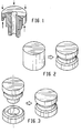
- An example of such a P/M element illustrating the vertical profile limitation is shown in Fig. 1.
- P/M parts must necessarily have a vertical profile to facilitate their release from the mold.
- the conventional P/M process is also not suitable for fashioning elements that have steeply sloped surfaces. If a surface is too steeply tapered the mold pressures will force the powder from the mold, thus prohibiting the formation of a tapered portion. Thus, tapered members of this type also require secondary machining.
- Another method of creating P/M parts with grooves, undercuts and the like is to sinter bond two green parts. As seen in Fig. 3, two parts with appropriately tapered surfaces are individually compacted and fitted together prior to sintering. Upon sintering, the two parts become bonded together to form an integral part with an appropriately placed groove or undercut. While this method is effective, a double compacting step is required since each part must be formed separately and then assembled prior to sintering. The sinter bonding process also requires two complex sets of tools as well as careful material considerations. Thus, this technique also fails to provide an economically viable alternative to the conventional P/M process.
- the prior art document US-A-2695320 is directed to a process of making powdered metal products.
- This process consists mainly in partially filling a die cavity with a quantity of metal powder, imbedding an infiltratable core in the die cavity, pressing the powdered metal into the desired form and sintering the pressed article whereupon the core disappears by infiltration into the pores of the powdered metal, leaving a cavity, indentation or other alteration of configuration corresponding to the shape previously possessed by the infiltrateable core.
- a process for forming a pressed metal part including the steps of inserting a preform into a pressed metal mold and filling the mold with powdered metal.
- the powdered metal and preform are compacted to create a compacted metal part wherein the preform defines an adjacent volume next to the compacted metal part.
- the compacted metal part is ejected from the mold and sintered to create a sintered metal part.
- the preform is removed by the sintering step in such a way that the adjacent volume becomes a void region.
- the preform can be formed of copper so that, upon sintering, the preform is removed from the sintered metal part through infiltration.
- the preform can be formed of zinc so that, upon sintering, the preform is vaporized and thereby removed from the sintered metal part.
- the void region created by the removal of the preform can be any manner of shape, including an undercut, a taper, an annular groove, a thread or an internal cavity. In this way, the present invention permits the creation of P/M parts having surfaces with other than vertical profile features such as have not been available through previous methods.
- a P/M mold 100 which uses a lower punch 102 and a die 104.
- the mold 100 is partially prefilled with an amount of powdered metal 106. This optional prefill can be lightly compacted to tamp the powder into an approximation of its final volume.
- a preform 108 is inserted into the mold 100.
- the preform 108 is preferably a compacted green part itself, formed by a previous compaction step. However, the preform can be casted or otherwise formed.
- the preform 108 is formed of a material which has a melting point lower than the temperature of fusion of the powdered metal to be sintered. For example, if the metal powder is a ferrous metal, having a fusion temperature of 2050°F, the preform is made of copper or zinc, which have respective melting temperatures of 1980°F and 787°F.
- the mold 100 is fully filled with metal powder 110.
- the amount of metal powder 110 in the mold is important since the size of the finished product is determined by the amount of powder and the degree of compaction.
- the powder is compacted.
- An upper punch 112 is brought down into the mold 100 and large forces are applied between the upper punch 112 and the lower punch 102 in order to create the tons per square inch pressures necessary for full compaction.
- the compacted part 114 is ejected from the mold 100 with the preform 108 compacted therein.
- the preform defines a volume which lies along a surface adjacent to the compacted part 114. This volume corresponds to the shape of the desired feature (i.e. groove, undercut, etc.)
- the compacted part 114 with preform 108 is sintered in a sintering oven 116. As the temperature of fusion is reached, the preform is melted off. In a ferrous part as according to the preferred embodiment, a copper preform would melt and be absorbed into the porous network of the compacted part 114. This absorption or "infiltration" results in a finished part with improved strength and metallurgical properties.
- the preform 108 can also be formed of a material such as zinc, which has a vaporization temperature of 1665°F. As the fusion temperature of a ferrous part is approached, the zinc melts and then vaporizes to become part of the furnace atmosphere. In this way, no portion of the preform 108 remains on the finished part.
- a finished sintered part 118 remains.
- the perform 108 has been completely removed by the sintering process.
- the preform 108 is necessarily formed with a "mirror image," i.e. a reverse profile of the desired groove.
- a void region is left adjacent to the sintered part 118 which corresponds to the desired profile, i.e. a groove, undercut, thread or the like.
- the desired profile i.e. a groove, undercut, thread or the like.
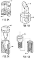
- Fig. 5A Examples of preforms and the parts made by the present process are shown in Fig. 5.
- a part 120 with a deep undercut can be made by first inserting the appropriate preform 122.
- Fig. 5B shows a crosshole member 130 formed using a cylindrical preform 132.
- Fig. 5D illustrates a piece 140 with a tapered surface having a reverse profile of that of the respective preform 142.
- Fig. 5D depicts a threaded member 150 by a threaded preform 152.
- a part 190 with an internal part 192 inside an internal cavity by imbedding the internal part 192 in the preform 194 prior to compacting.
- This internal part 192 can be, for example, an internal gear 192 which can ride within an internal gear profile 196 inside the internal cavity 194 with no apparent means for the ingress of the gear.
- P/M engineers will be able to design parts which exploit these advantages, thereby greatly expanding the potential for many types of future P/M products.
Landscapes
- Engineering & Computer Science (AREA)
- Manufacturing & Machinery (AREA)
- Mechanical Engineering (AREA)
- Powder Metallurgy (AREA)
Abstract
Description
Claims (7)
- A process for forming a pressed metal part comprising the steps of:a) partially pre-filling a pressed metal mold (100) with a predetermined amount of the powdered metal (106);b) lightly compacting the powder (106) to tamp the powder to an approximation of its final volume;c) inserting a vaporizable preform (108) into the mold (100);d) filling the mold (100) with powdered metal (110);e) compacting the powdered metal with the preform (108) to create a compacted metal part (114), wherein the preform (108) defines an adjacent volume next to the compacted metal part (114);f) ejecting the compacted metal part (114) from the mold (100);g) sintering said compacted metal part (114) to create a sintered metal part (118), wherein the preform (108) is substantially removed through vaporization by said sintering such that said adjacent volume becomes a substantially void region.
- The process of claim 1 wherein the preform comprises zinc.
- The process of claim 1 wherein said void region comprises an undercut.
- The process of claim 1 wherein said void region comprises a taper.
- The process of claim 1 wherein said void region comprises an annular groove.
- The process of claim 1 wherein said void region comprises a thread.
- The process of claim 1 wherein said void region comprises an internal cavity.
Applications Claiming Priority (3)
| Application Number | Priority Date | Filing Date | Title |
|---|---|---|---|
| US428560 | 1989-10-30 | ||
| US08/428,560 US5503795A (en) | 1995-04-25 | 1995-04-25 | Preform compaction powdered metal process |
| PCT/US1996/004950 WO1996033832A1 (en) | 1995-04-25 | 1996-04-11 | Process for compacting and sintering a powdered metal preform |
Publications (2)
| Publication Number | Publication Date |
|---|---|
| EP0822876A1 EP0822876A1 (en) | 1998-02-11 |
| EP0822876B1 true EP0822876B1 (en) | 1999-03-17 |
Family
ID=23699425
Family Applications (1)
| Application Number | Title | Priority Date | Filing Date |
|---|---|---|---|
| EP96911692A Expired - Lifetime EP0822876B1 (en) | 1995-04-25 | 1996-04-11 | Process for compacting and sintering a powdered metal preform |
Country Status (9)
| Country | Link |
|---|---|
| US (2) | US5503795A (en) |
| EP (1) | EP0822876B1 (en) |
| JP (2) | JPH11501989A (en) |
| AT (1) | ATE177668T1 (en) |
| BR (1) | BR9608143A (en) |
| CA (1) | CA2219319C (en) |
| DE (1) | DE69601790T2 (en) |
| ES (1) | ES2128854T3 (en) |
| WO (1) | WO1996033832A1 (en) |
Families Citing this family (36)
| Publication number | Priority date | Publication date | Assignee | Title |
|---|---|---|---|---|
| US5972027A (en) | 1997-09-30 | 1999-10-26 | Scimed Life Systems, Inc | Porous stent drug delivery system |
| US6080358A (en) * | 1997-12-24 | 2000-06-27 | Hitachi Powdered Metals Co., Ltd. | Method for forming compacts |
| DE19834571C2 (en) * | 1998-07-31 | 2001-07-26 | Daimler Chrysler Ag | Process for the production of bodies from fiber-reinforced composite materials and use of the process |
| US6042780A (en) * | 1998-12-15 | 2000-03-28 | Huang; Xiaodi | Method for manufacturing high performance components |
| US6554883B1 (en) | 1999-12-07 | 2003-04-29 | Mtd Products Inc. | Powdered metal gear teeth |
| US6232681B1 (en) | 2000-03-23 | 2001-05-15 | Delco Remy International, Inc. | Electromagnetic device with embedded windings and method for its manufacture |
| JP2004156131A (en) * | 2002-09-13 | 2004-06-03 | Honda Motor Co Ltd | Method for manufacturing metal compact |
| US6986866B2 (en) * | 2002-11-04 | 2006-01-17 | Kennametal Inc. | Method and apparatus for cross-hole pressing to produce cutting inserts |
| TW200416096A (en) * | 2003-01-31 | 2004-09-01 | Hideo Nakajima | Machine tool |
| DE502004004579D1 (en) | 2003-06-30 | 2007-09-20 | Mahle Motorkomponenten Schweiz | ROTOR OF SINTERED METAL OF A ROTARY PISTON PUMP |
| FR2863187B1 (en) * | 2003-12-09 | 2006-01-20 | Peugeot Citroen Automobiles Sa | METHOD FOR MANUFACTURING A PULLEY FOR DRIVING AND PULLEY PRODUCED ACCORDING TO SAID METHOD |
| US8210749B2 (en) * | 2007-03-23 | 2012-07-03 | Gkn Sinter Metals, Inc. | Powder metal bearing cap breathing windows |
| US7829015B2 (en) * | 2007-05-31 | 2010-11-09 | Borgwarner Inc. | Formation of non-axial features in compacted powder metal components |
| US7793579B1 (en) | 2007-08-05 | 2010-09-14 | Lee Robert G | Armor tile |
| US9187909B2 (en) | 2007-08-05 | 2015-11-17 | Robert G. Lee | Tile system |
| EP2215364B1 (en) * | 2007-11-13 | 2015-07-08 | Magna Powertrain Hückeswagen GmbH | Dye, sintered rotor and sintering method |
| US8033805B2 (en) * | 2007-11-27 | 2011-10-11 | Kennametal Inc. | Method and apparatus for cross-passageway pressing to produce cutting inserts |
| US8062014B2 (en) * | 2007-11-27 | 2011-11-22 | Kennametal Inc. | Method and apparatus using a split case die to press a part and the part produced therefrom |
| DE102008006690B4 (en) * | 2008-01-25 | 2010-01-07 | Glatt Systemtechnik Gmbh | Sintered hollow body |
| US20100290942A1 (en) * | 2009-05-15 | 2010-11-18 | Gm Global Technolgoy Operations, Inc. | Systems and methods to produce forged powder metal parts with transverse features |
| JP2014500396A (en) * | 2010-10-27 | 2014-01-09 | ジーケーエヌ シンター メタルズ、エル・エル・シー | Axial and radial holders for powder metal for molding applications |
| US9109269B2 (en) * | 2011-08-30 | 2015-08-18 | Baker Hughes Incorporated | Magnesium alloy powder metal compact |
| US9856547B2 (en) * | 2011-08-30 | 2018-01-02 | Bakers Hughes, A Ge Company, Llc | Nanostructured powder metal compact |
| US8784041B2 (en) | 2011-08-31 | 2014-07-22 | Pratt & Whitney Canada Corp. | Turbine shroud segment with integrated seal |
| US9079245B2 (en) | 2011-08-31 | 2015-07-14 | Pratt & Whitney Canada Corp. | Turbine shroud segment with inter-segment overlap |
| US8784037B2 (en) | 2011-08-31 | 2014-07-22 | Pratt & Whitney Canada Corp. | Turbine shroud segment with integrated impingement plate |
| US9028744B2 (en) | 2011-08-31 | 2015-05-12 | Pratt & Whitney Canada Corp. | Manufacturing of turbine shroud segment with internal cooling passages |
| US8784044B2 (en) | 2011-08-31 | 2014-07-22 | Pratt & Whitney Canada Corp. | Turbine shroud segment |
| JP6853008B2 (en) * | 2016-03-08 | 2021-03-31 | 株式会社ダイヤメット | Molding mold, molding method |
| JP6796433B2 (en) | 2016-08-18 | 2020-12-09 | 株式会社ダイヤメット | Molding mold, molding method |
| US10502093B2 (en) * | 2017-12-13 | 2019-12-10 | Pratt & Whitney Canada Corp. | Turbine shroud cooling |
| US10570773B2 (en) | 2017-12-13 | 2020-02-25 | Pratt & Whitney Canada Corp. | Turbine shroud cooling |
| US11274569B2 (en) | 2017-12-13 | 2022-03-15 | Pratt & Whitney Canada Corp. | Turbine shroud cooling |
| US10533454B2 (en) | 2017-12-13 | 2020-01-14 | Pratt & Whitney Canada Corp. | Turbine shroud cooling |
| GB201811430D0 (en) * | 2018-07-12 | 2018-08-29 | Rolls Royce Plc | Fabricating hollow components |
| US11365645B2 (en) | 2020-10-07 | 2022-06-21 | Pratt & Whitney Canada Corp. | Turbine shroud cooling |
Family Cites Families (28)
| Publication number | Priority date | Publication date | Assignee | Title |
|---|---|---|---|---|
| US2695230A (en) * | 1949-01-10 | 1954-11-23 | Michigan Powdered Metal Produc | Process of making powdered metal article |
| US3007794A (en) * | 1957-08-15 | 1961-11-07 | Birmingham Small Arms Co Ltd | Production of ducted articles |
| US3007784A (en) * | 1960-03-28 | 1961-11-07 | Standard Oil Co | Fuel oil composition |
| CA855149A (en) * | 1968-02-28 | 1970-11-03 | J. Havel Charles | Hot isostatic pressing using a vitreous container |
| US3554874A (en) * | 1968-05-31 | 1971-01-12 | Budd Co | Method of electroforming vessels |
| JPS5013205B1 (en) * | 1969-11-08 | 1975-05-17 | ||
| US3723585A (en) * | 1970-03-06 | 1973-03-27 | F Nussbaum | Method of electroformed molds |
| SE366673C (en) * | 1972-06-12 | 1984-04-09 | Asea Ab | PROCEDURE FOR THE PREPARATION OF QUICK STEELS WITH THE BASIS OF METAL POWDER |
| US3841870A (en) * | 1973-03-07 | 1974-10-15 | Carpenter Technology Corp | Method of making articles from powdered material requiring forming at high temperature |
| GB1443630A (en) * | 1973-12-19 | 1976-07-21 | Messerschmitt Boelkow Blohm | Method for the manufacture of articles of complex shape |
| US4261745A (en) * | 1979-02-09 | 1981-04-14 | Toyo Kohan Co., Ltd. | Method for preparing a composite metal sintered article |
| JPS6164801A (en) * | 1984-09-04 | 1986-04-03 | Nippon Kokan Kk <Nkk> | Method for forming powders such as metals and ceramics |
| US4752424A (en) * | 1986-01-30 | 1988-06-21 | Kabushiki Kaisha Toshiba | Method of manufacturing a rare earth oxysulfide ceramic |
| US4673549A (en) * | 1986-03-06 | 1987-06-16 | Gunes Ecer | Method for preparing fully dense, near-net-shaped objects by powder metallurgy |
| DE3640586A1 (en) * | 1986-11-27 | 1988-06-09 | Norddeutsche Affinerie | METHOD FOR PRODUCING HOLLOW BALLS OR THEIR CONNECTED WITH WALLS OF INCREASED STRENGTH |
| US4721598A (en) * | 1987-02-06 | 1988-01-26 | The Timken Company | Powder metal composite and method of its manufacture |
| US4736883A (en) * | 1987-02-25 | 1988-04-12 | Gte Products Corporation | Method for diffusion bonding of liquid phase sintered materials |
| DE3724156A1 (en) * | 1987-07-22 | 1989-02-02 | Norddeutsche Affinerie | METHOD FOR PRODUCING METALLIC OR CERAMIC HOLLOW BALLS |
| US4871621A (en) * | 1987-12-16 | 1989-10-03 | Corning Incorporated | Method of encasing a structure in metal |
| US4810462A (en) * | 1988-02-17 | 1989-03-07 | Iowa State University Research Foundation, Inc. | Method for fabricating prescribed flaws in the interior of metals |
| US4834938A (en) * | 1988-04-25 | 1989-05-30 | The Dow Chemical Company | Method for making composite articles that include complex internal geometry |
| GB8814916D0 (en) * | 1988-06-23 | 1988-07-27 | T & N Technology Ltd | Production of sealed cavity |
| US4975225A (en) * | 1989-03-07 | 1990-12-04 | United Technologies Corporation | Manufacture of monolithic, stiff, lightweight ceramic articles |
| JPH02280999A (en) * | 1989-04-18 | 1990-11-16 | Nkk Corp | Method for forming powders such as metals and ceramics |
| US5066454A (en) * | 1990-06-20 | 1991-11-19 | Industrial Materials Technology, Inc. | Isostatic processing with shrouded melt-away mandrel |
| US5130084A (en) * | 1990-12-24 | 1992-07-14 | United Technologies Corporation | Powder forging of hollow articles |
| US5227576A (en) * | 1991-03-14 | 1993-07-13 | Industrial Materials Technology | Method for forming complex patterns in the interior of a pressed part formed of compacted particulate material, and apparatus |
| US5393486A (en) * | 1993-12-09 | 1995-02-28 | Minnesota Mining And Manufacturing Company | Method for making orthodontic appliance having textured bonding surface |
-
1995
- 1995-04-25 US US08/428,560 patent/US5503795A/en not_active Expired - Lifetime
- 1995-12-20 US US08/575,215 patent/US5772748A/en not_active Expired - Fee Related
-
1996
- 1996-04-11 ES ES96911692T patent/ES2128854T3/en not_active Expired - Lifetime
- 1996-04-11 EP EP96911692A patent/EP0822876B1/en not_active Expired - Lifetime
- 1996-04-11 AT AT96911692T patent/ATE177668T1/en not_active IP Right Cessation
- 1996-04-11 DE DE69601790T patent/DE69601790T2/en not_active Expired - Fee Related
- 1996-04-11 CA CA002219319A patent/CA2219319C/en not_active Expired - Fee Related
- 1996-04-11 JP JP8532557A patent/JPH11501989A/en active Pending
- 1996-04-11 WO PCT/US1996/004950 patent/WO1996033832A1/en not_active Ceased
- 1996-04-11 BR BR9608143-0A patent/BR9608143A/en not_active IP Right Cessation
-
2000
- 2000-07-19 JP JP2000219816A patent/JP2001073011A/en active Pending
Also Published As
| Publication number | Publication date |
|---|---|
| US5503795A (en) | 1996-04-02 |
| JPH11501989A (en) | 1999-02-16 |
| CA2219319C (en) | 2002-09-03 |
| JP2001073011A (en) | 2001-03-21 |
| EP0822876A1 (en) | 1998-02-11 |
| CA2219319A1 (en) | 1996-10-31 |
| US5772748A (en) | 1998-06-30 |
| ATE177668T1 (en) | 1999-04-15 |
| BR9608143A (en) | 1999-12-07 |
| ES2128854T3 (en) | 1999-05-16 |
| DE69601790D1 (en) | 1999-04-22 |
| WO1996033832A1 (en) | 1996-10-31 |
| DE69601790T2 (en) | 1999-11-18 |
Similar Documents
| Publication | Publication Date | Title |
|---|---|---|
| US5503795A (en) | Preform compaction powdered metal process | |
| US7927528B2 (en) | Preform for manufacturing a material having a plurality of voids and method of making the same | |
| CA1163838A (en) | Method of hot consolidating powder with a recyclable container | |
| US6986866B2 (en) | Method and apparatus for cross-hole pressing to produce cutting inserts | |
| US5903815A (en) | Composite powdered metal component | |
| US4483820A (en) | Method of making sintered powder metallurgical bodies | |
| US20100290942A1 (en) | Systems and methods to produce forged powder metal parts with transverse features | |
| US5956561A (en) | Net shaped dies and molds and method for producing the same | |
| US4972898A (en) | Method of forming a piston containing a cavity | |
| CN111347046A (en) | Additive Manufacturing Using Two or More Sources of Atomized Metal Particles | |
| JP2005509521A (en) | Liquid phase sintered brazed molded product | |
| JPH03505350A (en) | Method of manufacturing articles of precise dimensions by sintering | |
| Greulich | Rapid prototyping and fabrication of tools and metal parts by laser sintering of metal powders | |
| AU2002305647B2 (en) | Preform for manufacturing a material having a plurality of voids and method of making same | |
| RU2101137C1 (en) | Method of manufacture of two-layer bushings | |
| JP2003171703A (en) | Porous sintered compact and its manufacturing method | |
| US20040151611A1 (en) | Method for producing powder metal tooling, mold cavity member | |
| AU2002305647A1 (en) | Preform for manufacturing a material having a plurality of voids and method of making same | |
| JP2000063908A (en) | Sintered forged part and method of manufacturing the same | |
| JPH04200969A (en) | Production of metal composite | |
| AU2007200458A1 (en) | Preform for manufacturing a material having a plurality of voids and method of making the same | |
| PL120799B1 (en) | Method of manufacturing non-porous pointed spot welding electrodes dlja tochechnojj svarki |
Legal Events
| Date | Code | Title | Description |
|---|---|---|---|
| PUAI | Public reference made under article 153(3) epc to a published international application that has entered the european phase |
Free format text: ORIGINAL CODE: 0009012 |
|
| 17P | Request for examination filed |
Effective date: 19971021 |
|
| AK | Designated contracting states |
Kind code of ref document: A1 Designated state(s): AT DE ES FR GB IT SE |
|
| GRAG | Despatch of communication of intention to grant |
Free format text: ORIGINAL CODE: EPIDOS AGRA |
|
| 17Q | First examination report despatched |
Effective date: 19980302 |
|
| GRAG | Despatch of communication of intention to grant |
Free format text: ORIGINAL CODE: EPIDOS AGRA |
|
| GRAH | Despatch of communication of intention to grant a patent |
Free format text: ORIGINAL CODE: EPIDOS IGRA |
|
| GRAH | Despatch of communication of intention to grant a patent |
Free format text: ORIGINAL CODE: EPIDOS IGRA |
|
| GRAA | (expected) grant |
Free format text: ORIGINAL CODE: 0009210 |
|
| AK | Designated contracting states |
Kind code of ref document: B1 Designated state(s): AT DE ES FR GB IT SE |
|
| REF | Corresponds to: |
Ref document number: 177668 Country of ref document: AT Date of ref document: 19990415 Kind code of ref document: T |
|
| REF | Corresponds to: |
Ref document number: 69601790 Country of ref document: DE Date of ref document: 19990422 |
|
| ET | Fr: translation filed | ||
| ITF | It: translation for a ep patent filed | ||
| REG | Reference to a national code |
Ref country code: ES Ref legal event code: FG2A Ref document number: 2128854 Country of ref document: ES Kind code of ref document: T3 |
|
| PLBE | No opposition filed within time limit |
Free format text: ORIGINAL CODE: 0009261 |
|
| STAA | Information on the status of an ep patent application or granted ep patent |
Free format text: STATUS: NO OPPOSITION FILED WITHIN TIME LIMIT |
|
| 26N | No opposition filed | ||
| REG | Reference to a national code |
Ref country code: GB Ref legal event code: IF02 |
|
| PGFP | Annual fee paid to national office [announced via postgrant information from national office to epo] |
Ref country code: SE Payment date: 20030404 Year of fee payment: 8 |
|
| PGFP | Annual fee paid to national office [announced via postgrant information from national office to epo] |
Ref country code: FR Payment date: 20030408 Year of fee payment: 8 |
|
| PGFP | Annual fee paid to national office [announced via postgrant information from national office to epo] |
Ref country code: GB Payment date: 20030409 Year of fee payment: 8 |
|
| PGFP | Annual fee paid to national office [announced via postgrant information from national office to epo] |
Ref country code: AT Payment date: 20030411 Year of fee payment: 8 |
|
| PGFP | Annual fee paid to national office [announced via postgrant information from national office to epo] |
Ref country code: ES Payment date: 20030429 Year of fee payment: 8 |
|
| PG25 | Lapsed in a contracting state [announced via postgrant information from national office to epo] |
Ref country code: GB Free format text: LAPSE BECAUSE OF NON-PAYMENT OF DUE FEES Effective date: 20040411 Ref country code: AT Free format text: LAPSE BECAUSE OF NON-PAYMENT OF DUE FEES Effective date: 20040411 |
|
| PG25 | Lapsed in a contracting state [announced via postgrant information from national office to epo] |
Ref country code: SE Free format text: LAPSE BECAUSE OF NON-PAYMENT OF DUE FEES Effective date: 20040412 Ref country code: ES Free format text: LAPSE BECAUSE OF NON-PAYMENT OF DUE FEES Effective date: 20040412 |
|
| EUG | Se: european patent has lapsed | ||
| GBPC | Gb: european patent ceased through non-payment of renewal fee |
Effective date: 20040411 |
|
| PG25 | Lapsed in a contracting state [announced via postgrant information from national office to epo] |
Ref country code: FR Free format text: LAPSE BECAUSE OF NON-PAYMENT OF DUE FEES Effective date: 20041231 |
|
| REG | Reference to a national code |
Ref country code: FR Ref legal event code: ST |
|
| PG25 | Lapsed in a contracting state [announced via postgrant information from national office to epo] |
Ref country code: IT Free format text: LAPSE BECAUSE OF NON-PAYMENT OF DUE FEES Effective date: 20050411 |
|
| PGFP | Annual fee paid to national office [announced via postgrant information from national office to epo] |
Ref country code: DE Payment date: 20050414 Year of fee payment: 10 |
|
| REG | Reference to a national code |
Ref country code: ES Ref legal event code: FD2A Effective date: 20040412 |
|
| PG25 | Lapsed in a contracting state [announced via postgrant information from national office to epo] |
Ref country code: DE Free format text: LAPSE BECAUSE OF NON-PAYMENT OF DUE FEES Effective date: 20061101 |