EP0822604A2 - Cylindrical battery - Google Patents
Cylindrical battery Download PDFInfo
- Publication number
- EP0822604A2 EP0822604A2 EP97113157A EP97113157A EP0822604A2 EP 0822604 A2 EP0822604 A2 EP 0822604A2 EP 97113157 A EP97113157 A EP 97113157A EP 97113157 A EP97113157 A EP 97113157A EP 0822604 A2 EP0822604 A2 EP 0822604A2
- Authority
- EP
- European Patent Office
- Prior art keywords
- metallic casing
- battery
- casing
- outside diameter
- electrode
- Prior art date
- Legal status (The legal status is an assumption and is not a legal conclusion. Google has not performed a legal analysis and makes no representation as to the accuracy of the status listed.)
- Withdrawn
Links
Images

Classifications
-
- H—ELECTRICITY
- H01—ELECTRIC ELEMENTS
- H01M—PROCESSES OR MEANS, e.g. BATTERIES, FOR THE DIRECT CONVERSION OF CHEMICAL ENERGY INTO ELECTRICAL ENERGY
- H01M10/00—Secondary cells; Manufacture thereof
- H01M10/04—Construction or manufacture in general
- H01M10/0431—Cells with wound or folded electrodes
-
- H—ELECTRICITY
- H01—ELECTRIC ELEMENTS
- H01M—PROCESSES OR MEANS, e.g. BATTERIES, FOR THE DIRECT CONVERSION OF CHEMICAL ENERGY INTO ELECTRICAL ENERGY
- H01M50/00—Constructional details or processes of manufacture of the non-active parts of electrochemical cells other than fuel cells, e.g. hybrid cells
- H01M50/50—Current conducting connections for cells or batteries
- H01M50/528—Fixed electrical connections, i.e. not intended for disconnection
-
- H—ELECTRICITY
- H01—ELECTRIC ELEMENTS
- H01M—PROCESSES OR MEANS, e.g. BATTERIES, FOR THE DIRECT CONVERSION OF CHEMICAL ENERGY INTO ELECTRICAL ENERGY
- H01M50/00—Constructional details or processes of manufacture of the non-active parts of electrochemical cells other than fuel cells, e.g. hybrid cells
- H01M50/50—Current conducting connections for cells or batteries
- H01M50/531—Electrode connections inside a battery casing
-
- H—ELECTRICITY
- H01—ELECTRIC ELEMENTS
- H01M—PROCESSES OR MEANS, e.g. BATTERIES, FOR THE DIRECT CONVERSION OF CHEMICAL ENERGY INTO ELECTRICAL ENERGY
- H01M50/00—Constructional details or processes of manufacture of the non-active parts of electrochemical cells other than fuel cells, e.g. hybrid cells
- H01M50/50—Current conducting connections for cells or batteries
- H01M50/543—Terminals
- H01M50/552—Terminals characterised by their shape
- H01M50/559—Terminals adapted for cells having curved cross-section, e.g. round, elliptic or button cells
- H01M50/56—Cup shaped terminals
-
- H—ELECTRICITY
- H01—ELECTRIC ELEMENTS
- H01M—PROCESSES OR MEANS, e.g. BATTERIES, FOR THE DIRECT CONVERSION OF CHEMICAL ENERGY INTO ELECTRICAL ENERGY
- H01M10/00—Secondary cells; Manufacture thereof
- H01M10/05—Accumulators with non-aqueous electrolyte
- H01M10/052—Li-accumulators
- H01M10/0525—Rocking-chair batteries, i.e. batteries with lithium insertion or intercalation in both electrodes; Lithium-ion batteries
-
- H—ELECTRICITY
- H01—ELECTRIC ELEMENTS
- H01M—PROCESSES OR MEANS, e.g. BATTERIES, FOR THE DIRECT CONVERSION OF CHEMICAL ENERGY INTO ELECTRICAL ENERGY
- H01M6/00—Primary cells; Manufacture thereof
- H01M6/04—Cells with aqueous electrolyte
- H01M6/06—Dry cells, i.e. cells wherein the electrolyte is rendered non-fluid
- H01M6/10—Dry cells, i.e. cells wherein the electrolyte is rendered non-fluid with wound or folded electrodes
-
- Y—GENERAL TAGGING OF NEW TECHNOLOGICAL DEVELOPMENTS; GENERAL TAGGING OF CROSS-SECTIONAL TECHNOLOGIES SPANNING OVER SEVERAL SECTIONS OF THE IPC; TECHNICAL SUBJECTS COVERED BY FORMER USPC CROSS-REFERENCE ART COLLECTIONS [XRACs] AND DIGESTS
- Y02—TECHNOLOGIES OR APPLICATIONS FOR MITIGATION OR ADAPTATION AGAINST CLIMATE CHANGE
- Y02E—REDUCTION OF GREENHOUSE GAS [GHG] EMISSIONS, RELATED TO ENERGY GENERATION, TRANSMISSION OR DISTRIBUTION
- Y02E60/00—Enabling technologies; Technologies with a potential or indirect contribution to GHG emissions mitigation
- Y02E60/10—Energy storage using batteries
-
- Y—GENERAL TAGGING OF NEW TECHNOLOGICAL DEVELOPMENTS; GENERAL TAGGING OF CROSS-SECTIONAL TECHNOLOGIES SPANNING OVER SEVERAL SECTIONS OF THE IPC; TECHNICAL SUBJECTS COVERED BY FORMER USPC CROSS-REFERENCE ART COLLECTIONS [XRACs] AND DIGESTS
- Y02—TECHNOLOGIES OR APPLICATIONS FOR MITIGATION OR ADAPTATION AGAINST CLIMATE CHANGE
- Y02P—CLIMATE CHANGE MITIGATION TECHNOLOGIES IN THE PRODUCTION OR PROCESSING OF GOODS
- Y02P70/00—Climate change mitigation technologies in the production process for final industrial or consumer products
- Y02P70/50—Manufacturing or production processes characterised by the final manufactured product
Definitions
- This invention uses a metallic casing, the outside diameter of which are larger than the outside diameter of the metallic casing in the finished battery, and relates to a cylindrical battery made by reducing the outside diameter of the metallic casing after the coiled battery element has been housed in the said metallic casing, being of relevance particularly to the improvement of manufacturing methods and reliability and safety.
- Portable electronic equipment as typified by notebook computers and video cameras, require enormous amounts of power.
- non-aqueous batteries are also required to generate large currents.
- Methods for reducing the internal resistance of batteries includes: 1) increasing electrode area, and; 2) reducing the resistance of electrode leads.
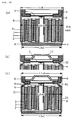
- strip-shaped electrodes In prior art the use of strip-shaped electrodes has been adopted to increase the area of electrodes. To increase electrode area of strip-shaped electrodes it is necessary to reduce the thickness of electrodes, with metallic foil generally being used as current collectors. That is to say, in prior art, strip-shaped negative electrode (1) and positive electrode (2) , the thicknesses of which have been reduced, are separated by separator (3) , and rolled up to form coiled battery element (20) , as shown in FIG. 13, with said battery element being housed in cylindrical metallic casing (4), the opening of which has a lid (7) affixed to it via a gasket (8) and is sealed to make a non-aqueous cylindrical batteries, as shown in FIG. 14 (b).
- either the positive electrode lead or negative electrode lead taken from the battery element is spot welded to the bottom of the metallic casing to obtain the electric conduct ion between the electrode and the metallic casing.
- the spot welder's rod-shaped electrode is inserted into the small hole formed in the centre of the coiled battery element when winding is conducted, and the electrode lead welded to the bottom of the metallic casing.
- the battery element is coiled, but a method is used in which the coiled electrode element is made by positioning the end of the negative electrode on the outermost periphery of the coiled electrode element and housing it in a cylindrical metallic casing to allow the aforementioned end of negative electrode positioned on the outermost periphery of the electrode element to come into contact with the internal wall of the metallic casing, enabling the electric conduction between the cathode and the metallic casing.
- alkaline electrolyte for example, 30% KOH aqueous solution
- relatively thick electrodes can be used, giving the electrodes a certain degree of resiliency. Accordingly, at the point in time when the electrode element is housed in the metallic casing the coiled electrode element has coil return due to the resiliency of the electrodes, giving enough contact strength for the electric conduction between the electrode terminal and the internal wall of the metallic casing.
- non-aqueous cylindrical batteries lithium batteries and lithium ion secondary batteries
- non-aqueous electrolyte organic electrolyte
- the conductivity of the electrolyte is no more than 1/50 of alkaline electrolyte, meaning that to create a non-aqueous battery from which a large current can be obtained it is necessary to increase the electrode area dramatically, necessitating an extremely thin electrode (100 - 200 microns).
- Electrodes which have metallic foil of no more than 0.03 mm in thickness as the current collector have extremely little resiliency, however, insufficient to provide enough return strength to allow electric conduct ion between the end of electrode and metallic casing. Accordingly, the only method adopted for obtaining the electric conduction between the electrode and metallic casing in conventional non-aqueous cylindrical batteries is to spot weld the electrode lead taken from the electrode element to the bottom of the metallic casing as mentioned previously.
- the reduction of electrode lead resistance is of great importance, not only in reducing the internal resistance of batteries, but also in respect of safety measures in that reduce overheating of electrode leads when large currents are flowing through them.
- the negative (or positive) lead (5) which is taken from the coiled battery element is welded to the bottom of metallic casing (4), the battery container (metallic casing) is the external terminal of the negative (or positive) electrode, the lead (6) of the other electrode, that is the positive (or negative) electrode, is welded to lid (7) to allow current to flow to the external terminal (10) of the positive (or negative) electrode.
- the cross-sectional area of the electrode lead should be increased and the length of the electrode lead shortened but, as shown in FIGs.
- the electrode leads are normally limited to a thin metallic plate the width and thickness of which are normally 4 - 6 mm and 0.04 - 0.1 mm respectively, and which needs to be reasonably long. That is to say, if the electrode lead is not narrow in width, it would not be possible to bring the lead out of the coil as shown in FIG. 13 (a), and if it is too thick proper welding will be difficult. Furthermore, as is shown in FIG.
- lead (6) is made sufficiently long to allow fitting of lid (7) on the inside of gasket (8), and as lead (5) welded to the center of the bottom of metallic casing (4) utilising the hole in the centre of the coiled battery element, lead (5) must be long enough to reach an appropriate welding point. In this conventional battery, therefore, it is not possible to sufficiently reduce the resistance value of the electrode lead, leaving an element of uncertainty as to safety in the event of an external short.
- a method of solving the first problem is to have the external dimensions of the metallic casing used when making a battery in which the outside diameter of the metallic casing in the finished battery is A, satisfy the relationship L2 > A ⁇ L3.
- L2 is the outside diameter of the central part of the metallic casing
- L3 is the "outside diameter of the casing bottom".
- Resolving the second problem entails separating with a separator a strip-shaped positive electrode and negative electrode, which have metallic foil of no more than 0.03 mm in thickness as a current collector, and winding them up into a jelly roll to make a battery element, the coiling of which is finished so that the end of electrode or electrode current collector of the negative electrode or positive electrode is positioned on the outermost periphery of said battery element, and housing the said battery element in a cylindrical metallic casing, after which the outside diameter of the said cylindrical metallic casing is reduced to strengthen the contact between the end of electrode or electrode current collector positioned on the outermost periphery of the battery element and the internal wall of the metallic casing, reducing the electric resistance of contact between the electrode and the metallic casing to a sufficiently small value.
- the first invention here proposes a metallic casing, the shape of the bottom and the dimension relationships of which differ from those of conventional metallic casings.
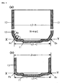
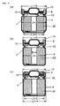
- FIG. 1(a) is a cross-section of the metallic casing prior to the Swaging used in this invention
- FIG. 1 (b) is a cross-section after Swaging.
- Metallic casings used in this invention are characterised in that they have casing walls perpendicular to the casing bottom, except in the vicinity of the casing bottom where the casing wall slants toward the casing bottom, resulting in two bends in the joining of the casing wall and casing bottom. As shown in the detailed diagram, in FIG.
- the joining of casing wall (12) and casing bottom (11) is accomplished with two bends represented by R1 and R2, thus making it possible to make the "outside diameter of the casing bottom" (L3) sufficiently small in comparison to the outside diameter (L2) of the central part of the metallic casing.
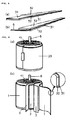
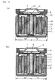
- electrodes used in this invention are a strip-shaped electrode to which an electrode lead is not attached as shown in FIG. 8 (a), and a strip-shaped electrode to which electrode lead (6) is attached as shown in FIG. 8 (b). These are made by inserting a separator and winding into a coil shape, then as shown in FIG. 9, completing the winding so that the end of electrode or electrode current collector (31) of strip-shaped electrode (1) to which an electrode lead is not attached, is positioned at the outermost periphery rather than the separator (3).
- Electrode lead (6) taken from one of the electrodes of the said battery element is welded to lid (7; normally also functions to prevent explosions) appropriately installed inside gasket (8), as shown in FIG. 10 (a).
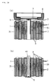
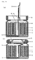
- the said battery element is impregnated electrolyte, the battery element housed in cylindrical metallic casing (4) the outside diameter (L2) of which is B, as shown in FIG. 11 (a), and the outside diameter (L2) of said cylindrical metallic casing reduced to A, (B > A), as shown in FIG. 11 (c), causing the end of electrode or electrode current collector positioned on the outermost periphery of the aforementioned battery element and the inside of the aforementioned metallic casing to be in very close contact over a broad area.
- electrodes with poor resiliency that have metallic foil of no more than 0.03 mm in thickness as current collectors, therefore, there is strong contact between the end of electrode or electrode current collector and the inside of the metallic casing, with sufficient electric conduction between electrode (1) and metallic casing (4) which forms the electrode's external terminal, eliminating the need for an electrode lead for electrode (1).
- electrode current collector (31) is positioned on the outermost periphery as shown in the enlarged sectional view of FIG. 9 (b) so the said current collector is in close contact with the inside of the metallic casing, allowing for sufficient electric conduction between the electrode and the metallic casing.
- the active substance layer has sufficient conductivity, with end of electrode positioned at the outermost periphery, even when there is an active substance layer on both sides of the current collector, the active substance layer at the outermost periphery will be in close contact with the inside of the metallic casing, enabling sufficient electric conduction between the electrode and the metallic casing.
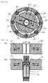
- FIG. 15 shows the principle diagram for this machine.
- Die (22) which has a hole (21) of ⁇ X in diameter in the centre, and divided into two in the centre, to the outside of which are attached several rollers (24) (FIG. 15 shows eight rollers).
- die (22) which is split in two, rotates in the direction of the arrow together with die holder (23), it comes into contact with a roller (24) every 45° of rotation, die (22) is tightened to the inside and the central gap in the split die (22) becomes smaller. Further rotation away from the rollers (24) results in the central gap widening.
- die (22) split in two approaches and withdraws, causing the diameter ⁇ X of the hole in the centre of the die to increase and decrease in size.
- Inserting a cylindrical object into hole (21) in the centre of die (22) which rotates, will squeeze the outside diameter of the object when the die (22), split into two, approaches (that is because it is tightened when diameter ⁇ X of the hole in the centre of the die becomes smaller).
- FIG. 16 (a) shows a vertical cross-section of the central part of the Swager's rotating die (22). The left and right die approach and withdraw as shown by the arrows.
- FIG. 16 (b) by inserting metallic casing (4) into the centre of the hole in the centre of rotating die (22), the outside diameter of the metallic casing can be squeezed to the outside diameter of the metallic casing in the finished battery.
- FIG. 1 shows detailed cross-section of the shape of the metallic casing bottom.
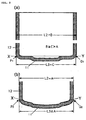
- FIG. 2 shows detailed cross-section of the shape of a conventional metallic casing bottom.
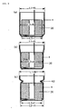
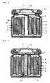
- FIG. 3 shows typical cross-section of battery in the assembly process.
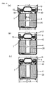
- FIG. 4 shows typical cross-section of battery in the assembly process.
- FIG. 5 shows typical cross-section of battery in the assembly process.
- FIG. 6 shows typical cross-section of battery.
- FIG. 7 shows typical cross-section of battery.
- FIG. 8 shows replication of strip-shaped electrode.
- FIG. 9 shows is replication of coiled battery element.
- FIG. 10 shows cross-section of coiled battery element.
- FIG. 11 shows cross-section of battery in sealing process.
- FIG. 12 shows cross-section of battery in sealing process.
- FIG. 13 shows cross-section of conventional coiled battery element .
- FIG. 14 shows cross-section of battery in conventional sealing process.
- FIG. 15 shows principle figure of Swager.
- FIG. 16 shows principle figure of Swaging. 1 Negative electrode 2 Positive electrode 3 Separator 4 Metallic casing 5 Negative electrode lead 6 Positive electrode lead 7 Sealing cap 8 Gasket 9 Central welding point of cap 10 Positive external terminal 11 Casing bottom 12 Casing wall 15 PTC element 20 Battery element 21 Die hole 22 Die 23 Die holder 24 Roller 31 Current collector 32 Active substance layer 40 Aluminium rod 41 Hole in centre of coil 42 Striations
- the specific battery manufacturing procedures for the first invention will be explained with reference to FIGs. 1,3 and 4.
- the battery element for the implementation of this invention is prepared in the following manner.
- PVDF polyvinylidene fluoride
- the positive electrode is also made under the publicly known conventional method as follows. Mix together well manganese dioxide (MnO 2 ) available on the market and lithium carbonate (Li 2 CO 3 ) in the ratio of 1 mol:0.275 mol, and bake in air at 800 °C for approximately 12 hours. Repeat the baking process three times to synthesize a spinel-type lithium-manganese compound oxide.
- MnO 2 manganese dioxide
- Li 2 CO 3 lithium carbonate
- this spinel type lithium-manganese compound oxide into powder form with an average particle size of 0.025 mm, and to 89 parts by weight of this powder mix 3 parts by weight of acetylene black and 4 parts by weight of graphite as conduction agents, and then wet blend with N-methyl-2-pyrrolidone into which 4 parts by weight of PVDF has been dissolved as a binding agent, to form a slurry.
- FIG. 3 (a) This embodiment seeks to make a battery in which the outside diameter (L2) of the metallic casing in the finished battery is 18.0 mm, while the metallic casing used is a nickel-plated iron casing with an outside diameter at the opening (L1) and outside diameter at the centre part (L2) of 18.5 mm, "outside diameter of the casing bottom" (L3) of 17.5 mm, and a height of 65 mm.
- the bottom of the said metallic casing is shown in the detailed diagram of FIG. 1(a).
- the FIG. 1(a) The FIG.
- the outside diameter of the battery element is 17.4 mm, and the inside diameter of the aforementioned metallic casing 17.9 mm, making the outside diameter of the battery element 0.5 mm smaller than the inside diameter of the casing, and allowing easy insertion of the battery element into the metallic casing.
- Swaging is conducted after battery element (20) is housed in metallic casing (4), and the outside diameter of the metallic casing (except the area around the casing opening) reduced to 18.0 mm, as shown in FIG. 3 (b).
- the "outside diameter of the casing bottom" (L3) of the metallic casing remains unchanged at 17.5 mm even after Swaging, as shown in the detailed diagram of FIG. 1 (b) the casing bottom of the metallic casing does not bulge in the Swaging process.
- the metallic casing is squeezed at a position 60.5 mm from the casing bottom (near the metallic casing opening), as shown in FIG. 3 (c), and striations (42) to support the gasket created.
- gasket (8) is installed in the opening of the metallic casing, and the negative lead and positive lead welded to the casing bottom and aluminium sealing lid (7; also acts as an explosion-proof valve), respectively, as shown in FIG. 4 (a).
- battery element (20) with an average outside diameter of 17.4 mm is made in exactly the same way as in Example 1.
- This example also seeks to make a battery in which the outside diameter of the metallic casing in the finished battery (L2) is 18.0 mm using the same metallic casing that was used in Example 1.
- Battery element (20) is housed in this metallic casing and, as shown in FIG. 5 (a), the metallic casing is squeezed at a position 60.5 mm from the casing bottom (near the metallic casing opening), and striations (42) to support the gasket created.
- the caulking machine is adjusted to a level where the tightening pressure will not damage the functions of the PTC element, and the edge of the metallic casing caulked and sealed to make battery (V) with a structure having an outside diameter of 18.0 mm and height of 65 mm as shown in FIG. 5(c).
- Example 2 the Swage Method has been used also in Example 2 to make battery (V). This differs from batteries made with conventional Swage Method in that there is no bulging at the casing bottom of the metallic casing, enabling a battery with flat casing bottom to be made.
- lithium-manganese oxide as the positive electrode active substance and carbon material as the negative electrode active substance
- this invention is essentially concerned with proposals for methods of making cylindrical batteries, and can naturally be applied to making cylindrical batteries for other battery systems.
- strip-shaped negative electrode (1) which has high-density active substance layer (32) on current collector (31).
- the end of electrode of prepared strip-shaped negative electrode (1) has no active substance layer on one side surface of the current collector, with current collector (31) exposed.
- the positive electrode is made under the publicly known method as follows.
- a spinel-type lithium-manganese compound oxide is synthesized as in Example 1. Make this spinel-type lithium-manganese compound oxide into powder form with an average particle size of 0.015 mm, and to 88 parts by weight of this powder, mix 6 parts by weight of graphite as a conductive agent, and then wet blend with N-methyl-2-pyrrolidone into which 6 parts by weight of PVDF has been dissolved as a binding agent, to form a positive electrode slurry.
- the inside diameter of the aforementioned metallic casing is 17.4 mm, and as the outside diameter of the battery element is made smaller than the inside diameter of the metallic casing the battery element can be easily inserted into the metallic casing.
- the metallic casing is squeezed down at a point 60.5 mm from the casing bottom, as shown in FIG. 11 (b), and striations (42) to support the gasket created.
- the edge of the metallic casing is then caulked to create battery (A) with a structure having an outside diameter of 17.5 mm and a height of 65 mm, as shown in FIG. 6.
- a coiled battery element is made in the same manner as Example 3, as shown in FIG. 9 (a).
- the aluminium rod (40) with diameter 4.0 mm is inserted into the centre hole (41) of the battery element as shown in FIG. 10 (b), and electrode lead taken from the centre of the coil is welded to one end of the said aluminium rod.
- the same type of electrolyte as was used in Example 1 is impregnated into said battery element and, as shown in FIG. 12 (a), the battery element is then housed in the cylindrical metallic casing with the side to which electrode lead (6) is welded facing the casing bottom.
- This embodiment also seeks to create a battery in which the outside diameter of the metallic casing in the finished battery is 17.5 mm, using the same metallic casing as used in Example 3.
- the metallic casing is squeezed in at a point 60.5 mm from the casing bottom, as shown in FIG. 12 (a), striations (42) created to support the gasket, and gasket (8) is installed in the opening of the metallic casing.
- the other end of the aforementioned aluminium rod is showing from the gasket's central hole, and when lid (7) is fitted inside the gasket the central part of the lid is in contact with the said end of the aluminium rod.
- Lid (7) is welded to at its centre point (9) to the end of the aluminium rod with a laser welder.
- a thinner section in the shape of a cross so that the lid functions to prevent explosion by splitting and safely releasing internal pressure when internal pressure in the battery rises.
- the edge of the metallic casing is then caulked to create battery (B) with a structure having an outside diameter of 17.5 mm and a height of 65 mm as shown in FIG. 7.
- electrode lead (6) which is welded to one end of the aluminium rod, is in close proximity to the hole in the centre of the coiled battery element it need only be a mere 4 mm in length.
- electrode lead with a tiny cross-sectional area of 0.16 mm 2 has a mere 4 mm lying between the battery element and the external terminal.
- This example also seeks to create a battery in which the outside diameter of the metallic casing in the finished battery is 17.5 mm, using the same metallic casing with an outside diameter of 18.0 mm as used in Example 3, and as the end of negative electrode (1) is positioned at the outermost periphery of the battery element, by housing the battery element in the cylindrical metallic casing and reducing the outside diameter of the metallic casing enables good electric conduction between the negative electrode and metallic casing (4).
- the outside diameter (B) of the metallic casing prior to Swaging is larger than the outside diameter (A) of the metallic casing in the finished battery, (B > A), and the "outside diameter of the casing bottom" (C) of the metallic casing is no more than the outside diameter (A) of the metallic casing in the finished battery, (A ⁇ C).
- negative electrode (1) and positive electrode (2) are created with the same method as in the aforementioned example, with the current collectors coated with an active substance layer, then pressurised casting is conducted to make strip-shaped electrodes. Under the conventional method, part of the current collector at one end of both the strip-shaped positive electrode and negative electrode are left exposed, to which electrode leads of 4 mm in width and 0.04 mm in thickness are welded.
- a separator is inserted between the prepared negative electrode and positive electrode, then this is wound into a jelly roll to make battery element (20) with an average outside diameter of 17.2 mm, as shown in FIG. 13 (a). Winding is done so electrode lead (6) attached to positive electrode (2) is positioned in the central part of the coil, and electrode lead (5) attached to negative electrode (1) is positioned at the outside of the coil. When winding is completed, separator (3) is positioned at the outermost periphery, as shown in FIG. 13 (b). In the battery element made in this way, negative electrode lead (5) is bent towards the centre of the battery element, as shown in FIG.
- Example 1 This is followed by the injection into the metallic casing a little at a time over five occasions of the same electrolyte as used in Example 1.
- the method involves a vacuum being created inside the metallic casing each time the electrolyte is injected, after which the electrolyte is injected, followed by pressurisation to promote the impregnation of the electrolyte into the battery element.
- electrode lead (6) is folded, as shown in FIG. 14 (b), lid (7) fitted inside gasket (8), positive external terminal (10) laid on top of and in contact with lid (7), and the edge of the metallic casing caulked and sealed to create battery (C) with the battery structure of an outside diameter of 18 mm and a height of 65 mm, as shown in FIG. 14 (b).
- electrode lead (6) In battery-making procedures under this conventional method, electrode lead (6) needs to be long enough to fold to ensure the appropriate installment of lid (7) in the process of installing lid (7) inside gasket (8).
- the length electrode lead (6) needs to be in order for it to be folded differs according to the outside diameter of the battery, that length being 22 mm in the case of the battery with an outside diameter of ⁇ 18 mm in this comparative example.
- the negative electrode lead taken from the battery element is spot welded to the casing bottom.
- welding cannot be performed properly if the negative electrode lead is wet with electrolyte, necessitating a method in which the battery element must first be housed in the metallic casing, the negative electrode lead spot welded to the casing base, and the electrolyte injected a little at a time over a number of times into the metallic casing and then impregnated into the battery element.
- batteries (A) and (B) of this invention achieved a 15 - 20% reduction in internal resistance without any deterioration of discharging characteristics in comparison with battery (C) of the conventional method.
- a 15 - 20% reduction in internal resistance means a 15 - 20% reduction in the internal heating of the battery even when large currents are being discharged, which is of great significance from a safety perspective.
- conventional battery (C) the entire 15 - 20% of extra heat arises only at the electrode leads which have very small heat capacity in relation to the total heat capacity inside the battery, leading to large temperature rises of the electrode leads when large currents are being discharged. This means that the electrode leads may become the source of ignition, particularly in the lithium ion secondary battery shown in this embodiment which uses combustible, organic electrolyte, causing the battery to catch fire.
- batteries (A) and (B) of the embodiments involved the battery element being housed in a cylindrical metallic casing, and the outside diameter of the said metallic casing being reduced, thus enabling very close contact over a large area between the end of electrode (electrode current collector) positioned at the outermost periphery of the battery element and the inside of the metallic casing. This means that there will be no batteries which do not function due to poor electric conduction between the metallic casing and the electrode.
- a specific embodiment for the second invention indicated a lithium ion secondary battery using lithium-manganese oxide as the positive electrode active substance, and a carbon material as the negative electrode active substance; this second invention is essentially concerned with proposals for methods of obtaining the electric conduction between electrodes and the external terminals.
- Non-aqueous cylindrical batteries naturally can be applied to other battery systems if they are batteries with a battery element that has a coiled structure.
- the coiled battery element in this invention is made by finishing the winding so as the end of electrode or electrode current collector of the negative electrode or the positive electrode is positioned at the outermost periphery of the battery element, then the said battery element is housed in the metallic casing, after which the outside diameter of the said metallic casing is reduced, thus the end of electrode or electrode current collector positioned at the outermost periphery of the battery element is in very close contact under high contact pressure with the inside wall of the metallic casing. This ensures the good electric conduction between either the negative electrode or the positive electrode and the metallic casing which is the external terminal of the electrode.
Landscapes
- Chemical & Material Sciences (AREA)
- Chemical Kinetics & Catalysis (AREA)
- Electrochemistry (AREA)
- General Chemical & Material Sciences (AREA)
- Engineering & Computer Science (AREA)
- Manufacturing & Machinery (AREA)
- Sealing Battery Cases Or Jackets (AREA)
- Primary Cells (AREA)
- Connection Of Batteries Or Terminals (AREA)
- Secondary Cells (AREA)
Abstract
To provide a method which allows a battery with a
flat base to be produced in a cylindrical battery
manufacturing method in which a metallic casing with a larger
outside diameter than the outside diameter of the metallic
casing in the finished battery is used, a battery element is
housed in the said metallic casing, then the outside diameter
of the metallic casing reduced; to reduce the occurrence of
defective batteries due to deficient electric conduction
between the metallic casing and the electrode lead; and to
improve the safety of the said cylindrical battery in the
event of an outside short circuit.
In the making of a battery in which the outside
diameter of the metallic casing in the finished battery is A,
the outside diameter of the metallic casing used is made to
satisfy the relationship L2 > A ≧ L3. The battery element,
made by winding in a coil shape, is wound so that when winding
is completed the end of electrode or electrode current
collector of either the negative electrode or the positive
electrode is positioned at the outermost periphery of the
battery element, then the said battery element is housed in a
cylindrical metallic casing, after which the outside diameter
of the said metallic casing is reduced to strengthen the
contact between the end of electrode or electrode current
collector positioned at the outermost periphery of the battery
element and the internal wall of the metallic casing, and make
the resistance electric of contact between the electrode and
metallic casing sufficiently small.
Description
This invention uses a metallic casing, the outside
diameter of which are larger than the outside diameter of the
metallic casing in the finished battery, and relates to a
cylindrical battery made by reducing the outside diameter of
the metallic casing after the coiled battery element has been
housed in the said metallic casing, being of relevance
particularly to the improvement of manufacturing methods and
reliability and safety.
The dissemination of and advances in various
portable electronic equipment, such as note-book computers and
video cameras, has been accompanied by heightened demand for
higher performance batteries as drive sources for these, with
attention being focused particularly on lithium batteries and
lithium ion secondary batteries. As lithium batteries and
lithium ion secondary batteries have high voltages, their
energy density is also high, contributing significantly to the
down-sizing and reduction in weight of portable electronic
equipment.
Further move towards smaller, lighter and more
sophisticated portable electronic equipment, however, has
given rise to even stronger demands for high performance
batteries, and in turn a need to boost energy density, even in
lithium batteries and lithium ion secondary batteries, as well
as reliability and safety.
To increase energy density a method was proposed
which used a metallic casing with outside diameter larger than
the outside diameter of the metallic casing in the finished
battery, and increased the diameter of the battery element
housed inside the metallic casing to boost capacity (JP-A-6-215792).
In this method a metallic casing is used which has
larger outside diameter (B) than the outside diameter (A) of
the metallic casing in the finished battery, and after housing
the battery element in the said metallic casing the outside
diameter of the metallic casing is squeezed down to the
outside diameters (A) of the metallic casing in the finished
battery (herein the squeezing of the outside diameter of the
metallic casing will be referred to as "Swaging", the machine
which squeezes the outside diameter of the metallic casing as
a "Swager", and the method of making a cylindrical battery in
which the outside diameter of the metallic casing is squeezed,
is called "Swage Method").
The use in the Swage Method of a metallic casing
with outside diameter larger than those of the outside
diameter of the metallic casing in the finished battery allows
the diameter of the battery element that is housed in the
metallic casing to be enlarged to boost capacity. As is shown
in FIG. 2 (b), however, a problem arises in the Swaging
process in which the bottom of the metallic casing bulges,
causing the external appearance to differ from that of
conventional batteries (flat bottom). The bulging of the
metallic casing bottom is something that is seen in
conventional batteries when a defect in the battery has
occurred leading to a rise in the battery's internal pressure,
while normal batteries have a flat bottom. As batteries with
bulged bottom tend to be deemed defective, and this is
undesirable, the Swage Method has not yet been put to
practical use.
Portable electronic equipment, as typified by notebook
computers and video cameras, require enormous amounts of
power. When used as power sources for such equipment, non-aqueous
batteries are also required to generate large
currents.
To create batteries from which large currents can be
obtained, the internal resistance of the battery must be
reduced as much as possible. Methods for reducing the
internal resistance of batteries includes: 1) increasing
electrode area, and; 2) reducing the resistance of electrode
leads.
In prior art the use of strip-shaped electrodes has
been adopted to increase the area of electrodes. To increase
electrode area of strip-shaped electrodes it is necessary to
reduce the thickness of electrodes, with metallic foil
generally being used as current collectors. That is to say,
in prior art, strip-shaped negative electrode (1) and positive
electrode (2) , the thicknesses of which have been reduced, are
separated by separator (3) , and rolled up to form coiled
battery element (20) , as shown in FIG. 13, with said battery
element being housed in cylindrical metallic casing (4), the
opening of which has a lid (7) affixed to it via a gasket (8)
and is sealed to make a non-aqueous cylindrical batteries, as
shown in FIG. 14 (b).
In conventional non-aqueous cylindrical batteries in
which the battery element is coiled, either the positive
electrode lead or negative electrode lead taken from the
battery element is spot welded to the bottom of the metallic
casing to obtain the electric conduct ion between the electrode
and the metallic casing. In this case, the spot welder's rod-shaped
electrode is inserted into the small hole formed in the
centre of the coiled battery element when winding is
conducted, and the electrode lead welded to the bottom of the
metallic casing. Under this method there is just one welding
site, welding defects are frequent, and it is not possible to
confirm whether the welding is sufficient or not, leading to
the problem in conventional non-aqueous cylindrical battery of
cases where the battery does not function due to improper
electric conduction between the metallic casing and the
electrode.
In conventional aqueous electrolyte-type nickel-cadmium
batteries and nickel-metal hydride batteries also, the
battery element is coiled, but a method is used in which the
coiled electrode element is made by positioning the end of the
negative electrode on the outermost periphery of the coiled
electrode element and housing it in a cylindrical metallic
casing to allow the aforementioned end of negative electrode
positioned on the outermost periphery of the electrode element
to come into contact with the internal wall of the metallic
casing, enabling the electric conduction between the cathode
and the metallic casing. As alkaline electrolyte (for
example, 30% KOH aqueous solution) have good conductivity,
there is no need for unreasonable increases of electrode area,
and relatively thick electrodes can be used, giving the
electrodes a certain degree of resiliency. Accordingly, at
the point in time when the electrode element is housed in the
metallic casing the coiled electrode element has coil return
due to the resiliency of the electrodes, giving enough contact
strength for the electric conduction between the electrode
terminal and the internal wall of the metallic casing.
As the resiliency of electrodes in non-aqueous
batteries is weak, however, no method is adopted to bring the
end of electrode into contact with the internal wall of the
metallic casing to allow the electric conduction between the
electrode and the metallic casing. In conventional non-aqueous
cylindrical batteries (lithium batteries and lithium
ion secondary batteries) which use non-aqueous electrolyte
(organic electrolyte) the conductivity of the electrolyte is
no more than 1/50 of alkaline electrolyte, meaning that to
create a non-aqueous battery from which a large current can be
obtained it is necessary to increase the electrode area
immensely, necessitating an extremely thin electrode (100 -
200 microns). For this reason it is preferable to use
metallic foil of no more than 0.03 mm in thickness as current
collectors for these electrodes. Electrodes which have
metallic foil of no more than 0.03 mm in thickness as the
current collector have extremely little resiliency, however,
insufficient to provide enough return strength to allow
electric conduct ion between the end of electrode and metallic
casing. Accordingly, the only method adopted for obtaining
the electric conduction between the electrode and metallic
casing in conventional non-aqueous cylindrical batteries is to
spot weld the electrode lead taken from the electrode element
to the bottom of the metallic casing as mentioned previously.
In cases where the electric conduct ion between the
electrode and the metallic casing is obtained by spot welding
the electrode to the metallic casing bottom, sufficient
welding cannot be performed if the electrode lead is wet. As
such the battery element had to first be put into the metallic
casing and the electrode lead spot welded to the bottom of the
metallic casing before the electrolyte could be impregnated
into the battery element. If the necessary quantity of
electrolyte is injected at one time with the battery element
already inside the metallic casing it would overflow from the
metallic casing, meaning that only a small amount could be
injected at one time. In the actual production process,
therefore, a considerable amount of time is allowed for the
impregnating of the electrolyte, with a little electrolyte
being injected each of three to five times, with a vacuum
being created for each injection. The electrolyte injection
process is a significant barrier in terms of actual mass
production.
Additionally, there is a problem with maintaining
safety with conventional batteries in which the battery
element is coiled. Because large currents can be obtained
from coiled battery elements, an accidental external short
circuit would result in the flow of an extremely large short
circuit current. In such cases all currents which are
generated at all electrodes would pass through the electrode
leads, with the heating of the electrode leads being a safety
problem. There are cases, particularly with non-aqueous
batteries (lithium batteries and lithium ion secondary
batteries) which use combustible organic electrolyte, in which
the electrode leads overheat and become the source of
ignition, causing the battery to catch fire.
Accordingly, the reduction of electrode lead
resistance is of great importance, not only in reducing the
internal resistance of batteries, but also in respect of
safety measures in that reduce overheating of electrode leads
when large currents are flowing through them.
As shown in FIG.14 (b), in conventional cylindrical
batteries the negative (or positive) lead (5) which is taken
from the coiled battery element is welded to the bottom of
metallic casing (4), the battery container (metallic casing)
is the external terminal of the negative (or positive)
electrode, the lead (6) of the other electrode, that is the
positive (or negative) electrode, is welded to lid (7) to
allow current to flow to the external terminal (10) of the
positive (or negative) electrode. To reduce the resistance of
the electrode lead the cross-sectional area of the electrode
lead should be increased and the length of the electrode lead
shortened but, as shown in FIGs. 13 and 14, due to the way the
electrode leads are brought out, the way they are welded to
the metallic casing and lid, and welding conditions, in
conventional cylindrical batteries the electrode leads are
normally limited to a thin metallic plate the width and
thickness of which are normally 4 - 6 mm and 0.04 - 0.1 mm
respectively, and which needs to be reasonably long. That is
to say, if the electrode lead is not narrow in width, it would
not be possible to bring the lead out of the coil as shown in
FIG. 13 (a), and if it is too thick proper welding will be
difficult. Furthermore, as is shown in FIG. 14, lead (6) is
made sufficiently long to allow fitting of lid (7) on the
inside of gasket (8), and as lead (5) welded to the center of
the bottom of metallic casing (4) utilising the hole in the
centre of the coiled battery element, lead (5) must be long
enough to reach an appropriate welding point. In this
conventional battery, therefore, it is not possible to
sufficiently reduce the resistance value of the electrode
lead, leaving an element of uncertainty as to safety in the
event of an external short.
One problem that this invention seeks to solve is to
realise the manufacture of cylindrical batteries with a Swage
Method which produces batteries with a flat bottom, and
provide a battery with high energy density. Another problem
the invention seeks to address in non-aqueous cylindrical
batteries which have battery elements made from coiled, strip-shaped
electrodes that have metallic foil of no more than 0.03
mm in thickness as current collectors, is the reduction in
defective batteries due to the poor electric conduction
between the metallic casing and electrode lead, and the
improvement of safety in the event of external shorts of said
cylindrical batteries.
A method of solving the first problem is to have the
external dimensions of the metallic casing used when making a
battery in which the outside diameter of the metallic casing
in the finished battery is A, satisfy the relationship L2 > A
≧ L3. Here L2 is the outside diameter of the central part of
the metallic casing, and L3 is the "outside diameter of the
casing bottom".
Resolving the second problem entails separating with
a separator a strip-shaped positive electrode and negative
electrode, which have metallic foil of no more than 0.03 mm in
thickness as a current collector, and winding them up into a
jelly roll to make a battery element, the coiling of which is
finished so that the end of electrode or electrode current
collector of the negative electrode or positive electrode is
positioned on the outermost periphery of said battery element,
and housing the said battery element in a cylindrical metallic
casing, after which the outside diameter of the said
cylindrical metallic casing is reduced to strengthen the
contact between the end of electrode or electrode current
collector positioned on the outermost periphery of the battery
element and the internal wall of the metallic casing, reducing
the electric resistance of contact between the electrode and
the metallic casing to a sufficiently small value.
The first invention here proposes a metallic casing,
the shape of the bottom and the dimension relationships of
which differ from those of conventional metallic casings.
FIG. 1(a) is a cross-section of the metallic casing prior to
the Swaging used in this invention, and FIG. 1 (b) is a cross-section
after Swaging. Metallic casings used in this
invention are characterised in that they have casing walls
perpendicular to the casing bottom, except in the vicinity of
the casing bottom where the casing wall slants toward the
casing bottom, resulting in two bends in the joining of the
casing wall and casing bottom. As shown in the detailed
diagram, in FIG. 1 (a) the joining of casing wall (12) and
casing bottom (11) is accomplished with two bends represented
by R1 and R2, thus making it possible to make the "outside
diameter of the casing bottom" (L3) sufficiently small in
comparison to the outside diameter (L2) of the central part of
the metallic casing. More specifically, the characteristic of
the metallic casing prior to the Swaging used in this
invention is that the outside diameter of the metallic casing
(L2 = B ) is larger than the outside diameter of the metallic
casing in the finished battery (L2 = A ) , (B > A) , and the
"outside diameter of the casing bottom" (L3 = C ) is no larger
than the outside diameter of the metallic casing in the
finished battery (L2 = A ) , (A ≧ C). Therefore, if the
metallic casing has the aforementioned dimensional
relationship (L2 > A ≧ L3) prior to Swaging, there will be no
change in the "outside diameter of the casing bottom" after
Swaging, as shown in FIG. 1 (b), and thus there will be no
bulging of the metallic casing bottom during the Swaging
process.
In the second proposed invention there is no need
for an electrode lead in at least one of either the negative
electrode or the positive electrode in the coiled battery
element (20) as shown in FIG. 9. That is, electrodes used in
this invention are a strip-shaped electrode to which an
electrode lead is not attached as shown in FIG. 8 (a), and a
strip-shaped electrode to which electrode lead (6) is attached
as shown in FIG. 8 (b). These are made by inserting a
separator and winding into a coil shape, then as shown in FIG.
9, completing the winding so that the end of electrode or
electrode current collector (31) of strip-shaped electrode (1)
to which an electrode lead is not attached, is positioned at
the outermost periphery rather than the separator (3).
Electrode lead (6) taken from one of the electrodes of the
said battery element is welded to lid (7; normally also
functions to prevent explosions) appropriately installed
inside gasket (8), as shown in FIG. 10 (a). Following this,
the said battery element is impregnated electrolyte, the
battery element housed in cylindrical metallic casing (4) the
outside diameter (L2) of which is B, as shown in FIG. 11 (a),
and the outside diameter (L2) of said cylindrical metallic
casing reduced to A, (B > A), as shown in FIG. 11 (c), causing
the end of electrode or electrode current collector positioned
on the outermost periphery of the aforementioned battery
element and the inside of the aforementioned metallic casing
to be in very close contact over a broad area. Even with
electrodes with poor resiliency that have metallic foil of no
more than 0.03 mm in thickness as current collectors,
therefore, there is strong contact between the end of
electrode or electrode current collector and the inside of the
metallic casing, with sufficient electric conduction between
electrode (1) and metallic casing (4) which forms the
electrode's external terminal, eliminating the need for an
electrode lead for electrode (1).
In cases where the active substance layer on the
metallic foil current collector does not have sufficient
conductivity also, with end of electrode positioned at the
outermost periphery, if, as shown in FIG. 8 (a), there is an
active substance layer (32) on just one side of current
collector (31), electrode current collector (31) is positioned
on the outermost periphery as shown in the enlarged sectional
view of FIG. 9 (b) so the said current collector is in close
contact with the inside of the metallic casing, allowing for
sufficient electric conduction between the electrode and the
metallic casing. Naturally when the active substance layer
has sufficient conductivity, with end of electrode positioned
at the outermost periphery, even when there is an active
substance layer on both sides of the current collector, the
active substance layer at the outermost periphery will be in
close contact with the inside of the metallic casing, enabling
sufficient electric conduction between the electrode and the
metallic casing.
A machine marketed under the name Swager may be used
to squeeze the outside diameter of the metallic casing. FIG.
15 shows the principle diagram for this machine. Held in die
holder (23) and positioned in the centre is die (22) which has
a hole (21) of ⊘ X in diameter in the centre, and divided into
two in the centre, to the outside of which are attached
several rollers (24) (FIG. 15 shows eight rollers). When die
(22), which is split in two, rotates in the direction of the
arrow together with die holder (23), it comes into contact
with a roller (24) every 45° of rotation, die (22) is
tightened to the inside and the central gap in the split die
(22) becomes smaller. Further rotation away from the rollers
(24) results in the central gap widening. This means that die
(22) split in two, approaches and withdraws, causing the
diameter ⊘ X of the hole in the centre of the die to increase
and decrease in size. Inserting a cylindrical object into
hole (21) in the centre of die (22) , which rotates, will
squeeze the outside diameter of the object when the die (22),
split into two, approaches (that is because it is tightened
when diameter ⊘ X of the hole in the centre of the die becomes
smaller).
Use of the Swager allows the cylindrical battery of
this invention to be made by squeezing the outside diameter of
the metallic casing. FIG. 16 (a) shows a vertical cross-section
of the central part of the Swager's rotating die (22).
The left and right die approach and withdraw as shown by the
arrows. As shown in FIG. 16 (b), by inserting metallic casing
(4) into the centre of the hole in the centre of rotating die
(22), the outside diameter of the metallic casing can be
squeezed to the outside diameter of the metallic casing in the
finished battery.
The examples presented below will provide detailed
explanations of the aforementioned two inventions.
FIG. 1 shows detailed cross-section of the shape of
the metallic casing bottom.
FIG. 2 shows detailed cross-section of the shape of
a conventional metallic casing bottom.
FIG. 3 shows typical cross-section of battery in the
assembly process.
FIG. 4 shows typical cross-section of battery in the
assembly process.
FIG. 5 shows typical cross-section of battery in the
assembly process.
FIG. 6 shows typical cross-section of battery.
FIG. 7 shows typical cross-section of battery.
FIG. 8 shows replication of strip-shaped electrode.
FIG. 9 shows is replication of coiled battery
element.
FIG. 10 shows cross-section of coiled battery
element.
FIG. 11 shows cross-section of battery in sealing
process.
FIG. 12 shows cross-section of battery in sealing
process.
FIG. 13 shows cross-section of conventional coiled
battery element .
FIG. 14 shows cross-section of battery in
conventional sealing process.
FIG. 15 shows principle figure of Swager.
FIG. 16 shows principle figure of Swaging.
| 1 | | 2 | |
| 3 | | 4 | |
| 5 | | ||
| 6 | | ||
| 7 | | 8 | Gasket |
| 9 | Central welding point of | ||
| 10 | Positive | ||
| 11 | Casing bottom | 12 | |
| 15 | | 20 | |
| 21 | | 22 | |
| 23 | | 24 | |
| 31 | | 32 | |
| 40 | | 41 | Hole in centre of |
| 42 | Striations |
The specific battery manufacturing procedures for
the first invention will be explained with reference to FIGs.
1,3 and 4. The battery element for the implementation of this
invention is prepared in the following manner.
First the negative electrode is prepared under the
publicly known conventional method as follows. Combine 87
parts by weight of mesocarbon micro beads (d002 = 3.37 Å )
which have been heat treated at 2800 °C with 3 parts by weight
of acetylene black and wet blend with 10 parts by weight of
polyvinylidene fluoride (PVDF) as a binding agent and N-methly-2-pyrrolidone
as solvent to make a wet slurry. Next,
apply the slurry evenly to both surfaces of the copper foil of
0.01 mm in thickness which is to be the negative electrode
current collector, and once it has dried, conduct pressurised
casting with a roll press to form a strip-shaped negative
electrode. Have part of the current collector exposed at one
edge of the strip-shaped negative electrode and onto it weld a
nickel negative electrode lead.
The positive electrode is also made under the
publicly known conventional method as follows. Mix together
well manganese dioxide (MnO2) available on the market and
lithium carbonate (Li2CO3) in the ratio of 1 mol:0.275 mol,
and bake in air at 800 °C for approximately 12 hours. Repeat
the baking process three times to synthesize a spinel-type
lithium-manganese compound oxide. Make this spinel type
lithium-manganese compound oxide into powder form with an
average particle size of 0.025 mm, and to 89 parts by weight
of this powder mix 3 parts by weight of acetylene black and 4
parts by weight of graphite as conduction agents, and then wet
blend with N-methyl-2-pyrrolidone into which 4 parts by weight
of PVDF has been dissolved as a binding agent, to form a
slurry. Next, apply the slurry evenly to both surfaces of the
aluminium foil of 0.02 mm in thickness which is to be the
positive electrode current collector, and once it has dried,
conduct pressurised casting with a roll press to form a strip-shaped
positive electrode. Have part of the aluminium exposed
at one edge of the strip-shape positive electrode and onto it
weld an aluminium positive electrode lead.
Insert a porous, polypropylene separator between the
prepared negative and positive electrodes and roll up to
create a battery element (20) with an average outside diameter
of 17.4 mm. Then battery element (20) is housed in metallic
casing (4), as shown in FIG. 3 (a). This embodiment seeks to
make a battery in which the outside diameter (L2) of the
metallic casing in the finished battery is 18.0 mm, while the
metallic casing used is a nickel-plated iron casing with an
outside diameter at the opening (L1) and outside diameter at
the centre part (L2) of 18.5 mm, "outside diameter of the
casing bottom" (L3) of 17.5 mm, and a height of 65 mm. The
bottom of the said metallic casing is shown in the detailed
diagram of FIG. 1(a). The FIG. 1(a) shows that it has two
bends represented by R1 and R2 at the join of casing wall (12)
and casing bottom (11), making it possible to make the
"outside diameter of the casing bottom" (L3) sufficiently
small in comparison to the outside diameter of the centre part
of the metallic casing (L2). That is, the characteristic of
the metallic casing prior to the Swaging used in this
embodiment is that the outside diameter of the metallic casing
(L2 = B = 18.5 mm ) is larger than the outside diameter of the
metallic casing in the finished battery (L2 = A = 18.0 mm ), (B
>A), and the "outside diameter of the casing bottom" of the
metallic casing (L3 = C = 17.5 mm ) is no more than the outside
diameter of the metallic casing in the finished battery (L2 =
A = 18.0 mm ), (A ≧ C).
On the other hand, the outside diameter of the
battery element is 17.4 mm, and the inside diameter of the
aforementioned metallic casing 17.9 mm, making the outside
diameter of the battery element 0.5 mm smaller than the inside
diameter of the casing, and allowing easy insertion of the
battery element into the metallic casing. Swaging is
conducted after battery element (20) is housed in metallic
casing (4), and the outside diameter of the metallic casing
(except the area around the casing opening) reduced to 18.0
mm, as shown in FIG. 3 (b). As the "outside diameter of the
casing bottom" (L3) of the metallic casing remains unchanged
at 17.5 mm even after Swaging, as shown in the detailed
diagram of FIG. 1 (b) the casing bottom of the metallic casing
does not bulge in the Swaging process.
Following this, the metallic casing is squeezed at a
position 60.5 mm from the casing bottom (near the metallic
casing opening), as shown in FIG. 3 (c), and striations (42)
to support the gasket created. After this the process in FIG.
4 (a) to (c) are followed to assemble the battery. That is,
gasket (8) is installed in the opening of the metallic casing,
and the negative lead and positive lead welded to the casing
bottom and aluminium sealing lid (7; also acts as an
explosion-proof valve), respectively, as shown in FIG. 4 (a).
Next, electrolyte is injected, sealing lid (7) fitted to the
gasket, doughnut-shaped PTC element (15) laid on top of and in
contact with the sealing lid, positive external terminal (10)
laid on top, and the Swager used once again to squeeze the
outside diameter of the metallic casing opening (L1) to the
same size as the outside diameter of the central part of the
metallic casing (L2) (FIG. 4 (b)). Finally, the caulking
machine is adjusted to a level where the tightening pressure
will not damage the functions of the PTC element, and the edge
of the metallic casing caulked and sealed to make battery (U)
having the battery structure shown in FIG. 4 (c) with an
outside diameter of 18.0 mm, a height of 65 mm, and a flat
bottom.
Another specific example of the first invention will
be explained with reference to FIG. 5. First, battery element
(20) with an average outside diameter of 17.4 mm is made in
exactly the same way as in Example 1. This example also seeks
to make a battery in which the outside diameter of the
metallic casing in the finished battery (L2) is 18.0 mm using
the same metallic casing that was used in Example 1. Battery
element (20) is housed in this metallic casing and, as shown
in FIG. 5 (a), the metallic casing is squeezed at a position
60.5 mm from the casing bottom (near the metallic casing
opening), and striations (42) to support the gasket created.
At the point in time when the striations are created the
relationship between the outside diameter of the metallic
casing opening (L1) and the outside diameter of the central
part of the metallic casing (L2) is L1 = L2 = 18.5 mm . Next,
as shown in FIG. 5 (a) , gasket (8) is installed at the opening
of the metallic casing, and the negative lead and positive
lead welded to the casing bottom and sealing lid (7; also acts
as an explosion-proof valve), respectively, as shown in FIG. 5
(a). Next, same electrolyte as example 1 is injected,
sealing lid (7) fitted in the gasket, doughnut-shaped PTC
element (15) laid on top of and in contact with the sealing
lid, positive external terminal (10) laid on top, and the
Swager used to squeeze the entire outside diameter of the
metallic casing from the bottom to the opening to reduce the
outside diameter of the metallic casing to 18.0 mm (FIG. 5
(b)). As shown in the detailed diagram of FIG. 1 (b), the
bottom of the metallic casing after Swaging has an "outside
diameter of the casing bottom" (L3) which remains unchanged at
17.5mm even after Swaging, thus the bottom of the metallic
casing does not bulge in the Swaging process. Finally, the
caulking machine is adjusted to a level where the tightening
pressure will not damage the functions of the PTC element, and
the edge of the metallic casing caulked and sealed to make
battery (V) with a structure having an outside diameter of
18.0 mm and height of 65 mm as shown in FIG. 5(c).
As presented above, the Swage Method has been used
also in Example 2 to make battery (V). This differs from
batteries made with conventional Swage Method in that there is
no bulging at the casing bottom of the metallic casing,
enabling a battery with flat casing bottom to be made.
Furthermore, the creation of a lithium ion secondary
battery using lithium-manganese oxide as the positive
electrode active substance and carbon material as the negative
electrode active substance was indicated as a specific
embodiment of the first invention in Examples 1 and 2; this
invention is essentially concerned with proposals for methods
of making cylindrical batteries, and can naturally be applied
to making cylindrical batteries for other battery systems.
Specific procedures for making batteries will be
explained in relation to the second invention, with reference
to FIGs. 6, and 8 to 11. Preparation of the battery element
to implement the second invention differs from conventional
method and is as follows.
First dry blend 70 parts by weight of mesocarbon
micro beads (d002 = 3.37 Å ) which have been heat treated at
2800 °C with 20 parts by weight of pitch cokes, then wet blend
with N-methyl-2-pyrrolidone, into which 10 parts by weight of
polyvinylidene fluoride (PVDF) has been dissolved as a binding
agent, to create the negative electrode slurry. Apply the
negative electrode slurry evenly to both sides of copper foil
of 0.01 mm in thickness which is to be the negative electrode
current collector, leaving only 56 mm on one side of the
copper foil uncoated, as shown in FIG. 8 (a). Once it has
dried, conduct pressurised casting with a roll press to
prepare strip-shaped negative electrode (1) which has high-density
active substance layer (32) on current collector (31).
As shown in FIG. 8 (a), the end of electrode of prepared
strip-shaped negative electrode (1) has no active substance
layer on one side surface of the current collector, with
current collector (31) exposed.
The positive electrode is made under the publicly
known method as follows. A spinel-type lithium-manganese
compound oxide is synthesized as in Example 1. Make this
spinel-type lithium-manganese compound oxide into powder form
with an average particle size of 0.015 mm, and to 88 parts by
weight of this powder, mix 6 parts by weight of graphite as a
conductive agent, and then wet blend with N-methyl-2-pyrrolidone
into which 6 parts by weight of PVDF has been
dissolved as a binding agent, to form a positive electrode
slurry. Next, apply the slurry evenly to both surfaces of the
aluminium foil of 0.02 mm in thickness which is to be the
positive electrode current collector, and once it has dried,
conduct pressurised casting with a roll press to form, as
shown in FIG. 8 (b), strip-shaped positive electrode (2) which
has high density active substance layer (32) on current
collector (31). As with the positive electrode in Example 1,
have part of the current collector of strip-shaped positive
electrode (2) exposed at one end and onto it weld aluminium
positive electrode lead (6) of 4 mm in width and 0.04 mm in
thickness.
Insert a porous, polypropylene separator (3) in
between negative electrode (1) and positive electrode (2), and
wind into a jelly roll to create battery element (20) with an
average outside diameter of 17 mm, as shown in FIG. 9 (a). As
the cross-section of battery elements made by coiling strip-shaped
electrodes generally will not be a complete circle,
there are maximum and minimum values for the outside diameter
of battery element (20), with the maximum outside diameter
value for battery element (20) made here being 17.15 mm. When
winding, electrode lead (6) attached to the positive electrode
is positioned in the centre of the jelly roll and, as shown in
FIG. 9 (b), winding is completed so that the end of electrode
with the exposed current collector of negative electrode (1),
rather than separator (3), is positioned at the outermost
periphery. Additionally, as shown in FIG. 10 (a), lead (6)
taken from the centre of the battery element is welded to lid
(7) which is installed inside gasket (8). After this,
electrolyte, consisting of a blended solvent of ethylene
carbonate (EC) and diethyl carbonate (DEC) into which 1 mol/l
of LiPF6 has been dissolved, is impregnated into the said
battery element, and put into cylindrical metallic casing (4)
as shown in FIG. 11 (a).
This embodiment seeks to make a battery in which the
outside diameter (A) of the metallic casing of the finished
battery is 17.5 mm, while the metallic casing used is a
nickel-plated iron casing with an outside diameter at the
opening (L1) and outside diameter at the centre part (L2) of B
= 18.0 mm, "outside diameter of the casing bottom" (L3) of C
= 16.5 mm, and a height of 65 mm. The outside diameter of the
metallic casing used in this example (L2 = B = 18.0 mm ) is
larger than the outside diameter of the metallic casing in the
finished battery (L2 = A = 17.5 mm ), (B >A), and the "outside
diameter of the casing bottom" of the metallic casing (L3 = C
= 16.5 mm ) is no more than the outside diameter of the
metallic casing in the finished battery (L2 = A = 17.5 mm ), (A
≧ C).
As a matter of interest, the inside diameter of the
aforementioned metallic casing is 17.4 mm, and as the outside
diameter of the battery element is made smaller than the
inside diameter of the metallic casing the battery element can
be easily inserted into the metallic casing. After housing
battery element (20) in metallic casing (4), the metallic
casing is squeezed down at a point 60.5 mm from the casing
bottom, as shown in FIG. 11 (b), and striations (42) to
support the gasket created. Following this, positive external
terminal (10) is laid on top and in contact with sealing lid
(7), and the outside diameter of the metallic casing squeezed
to outside diameter of L2 = A = 17.5 mm , as shown in FIG. 11
(c). The edge of the metallic casing is then caulked to
create battery (A) with a structure having an outside
diameter of 17.5 mm and a height of 65 mm, as shown in FIG. 6.
In battery (A) made in this way, because the battery
element (20) is housed in metallic casing (4), after which the
outside diameter of the metallic casing is reduced, thus the
end of electrode positioned at the outermost periphery of the
battery element is in very close contact over a large area
with the internal wall of the metallic casing. Naturally the
degree of contact between the end of electrode and internal
wall of the metallic casing closely correlates to the degree
of change in the outside diameter of the battery element at
this time. That is, it can be said that if the maximum value
of the outside diameter of the battery element prior to
insertion in the metallic casing is D mm, and the maximum
value of the inside diameter of the metallic casing after
squeezing the outside diameter is d mm, then the greater (D-d)
is, the stronger the degree of contact between the end of
electrode and the internal wall of the metallic casing. As in
this embodiment, D = 17.15 mm and d = 16.95 mm, (D-d) = 0.20
mm and, as shown in the enlarged sectional view of FIG. 9 (b),
since electrode current collector (31) is positioned at the
outermost periphery of the battery element, the said current
collector is in appropriate close contact over a large area
with the inside of metallic casing (4). Thus, as in this
embodiment, by setting (D-d) appropriately, positioning the
end of one electrode or current collector at the outermost
periphery of the battery element, housing it in a cylindrical
metallic casing and reducing the outside diameter of the
metallic casing, good electric conduction can be obtained
between at least one electrode, without the need for an
electrode lead, and metallic casing (4), which is the
electrode external terminal. Furthermore, if (D-d) is too
large the battery element may be overly tightened, causing
internal shorts. Other experiments confirmed that it should
be 0 < (D-d) ≦ 0.3 , with this example being (D-d) = 0.20 mm .
A preferable range of (D-d) is about 0.1 mm to about 0.25 mm.
In this example also, the outside diameter of the
metallic casing prior to Swaging (L2 = B ) is larger than the
outside diameter of the metallic casing in the finished
battery (L2 = A ) , (B > A), and the "outside diameter of the
casing bottom" of the metallic casing (L3 = C ) is no more than
the outside diameter of the metallic casing in the finished
battery (L2 =A ), (A ≧ C). As such, there is no change in the
"outside diameter casing bottom" (L3) even after Swaging and
no bulging of the casing bottom of the metallic casing in the
Swaging process.
Another specific example of the second invention
will be explained with reference to FIG.s 7 to 10, and 12. A
coiled battery element is made in the same manner as Example
3, as shown in FIG. 9 (a). The aluminium rod (40) with
diameter 4.0 mm is inserted into the centre hole (41) of the
battery element as shown in FIG. 10 (b), and electrode lead
taken from the centre of the coil is welded to one end of the
said aluminium rod. Following this, the same type of
electrolyte as was used in Example 1 is impregnated into said
battery element and, as shown in FIG. 12 (a), the battery
element is then housed in the cylindrical metallic casing with
the side to which electrode lead (6) is welded facing the
casing bottom. This embodiment also seeks to create a battery
in which the outside diameter of the metallic casing in the
finished battery is 17.5 mm, using the same metallic casing as
used in Example 3. After housing the battery element in
metallic casing (4), the metallic casing is squeezed in at a
point 60.5 mm from the casing bottom, as shown in FIG. 12 (a),
striations (42) created to support the gasket, and gasket (8)
is installed in the opening of the metallic casing. The other
end of the aforementioned aluminium rod is showing from the
gasket's central hole, and when lid (7) is fitted inside the
gasket the central part of the lid is in contact with the said
end of the aluminium rod. Lid (7) is welded to at its centre
point (9) to the end of the aluminium rod with a laser welder.
In the centre of the lid used here is created a thinner
section in the shape of a cross, so that the lid functions to
prevent explosion by splitting and safely releasing internal
pressure when internal pressure in the battery rises.
Positive external terminal (10) is then laid on top of and in
contact with sealing lid (7), and, as shown in FIG. 12 (b),
the outside diameter of metallic casing B = 18.0 mm, is
squeezed to A = 17.5 mm using the same method as in the
aforementioned example. The edge of the metallic casing is
then caulked to create battery (B) with a structure having an
outside diameter of 17.5 mm and a height of 65 mm as shown in
FIG. 7. As electrode lead (6), which is welded to one end of
the aluminium rod, is in close proximity to the hole in the
centre of the coiled battery element it need only be a mere 4
mm in length. In the end, in battery (B) made in this
embodiment, electrode lead with a tiny cross-sectional area of
0.16 mm2 has a mere 4 mm lying between the battery element and
the external terminal.
This example also seeks to create a battery in which
the outside diameter of the metallic casing in the finished
battery is 17.5 mm, using the same metallic casing with an
outside diameter of 18.0 mm as used in Example 3, and as the
end of negative electrode (1) is positioned at the outermost
periphery of the battery element, by housing the battery
element in the cylindrical metallic casing and reducing the
outside diameter of the metallic casing enables good electric
conduction between the negative electrode and metallic casing
(4).
In this example also, the outside diameter (B) of
the metallic casing prior to Swaging is larger than the
outside diameter (A) of the metallic casing in the finished
battery, (B > A), and the "outside diameter of the casing
bottom" (C) of the metallic casing is no more than the outside
diameter (A) of the metallic casing in the finished battery,
(A ≧ C). As such, there is no change in the "outside
diameter of the casing bottom" even after Swaging and no
bulging of the bottom of the metallic casing in the Swaging
process.
The conventional procedures for making batteries
will be explained with reference to FIGs. 13 and 14. In
conventional battery-making methods the battery element is
prepared as follows.
First, negative electrode (1) and positive electrode
(2) are created with the same method as in the aforementioned
example, with the current collectors coated with an active
substance layer, then pressurised casting is conducted to make
strip-shaped electrodes. Under the conventional method, part
of the current collector at one end of both the strip-shaped
positive electrode and negative electrode are left exposed, to
which electrode leads of 4 mm in width and 0.04 mm in
thickness are welded.
A separator is inserted between the prepared
negative electrode and positive electrode, then this is wound
into a jelly roll to make battery element (20) with an average
outside diameter of 17.2 mm, as shown in FIG. 13 (a). Winding
is done so electrode lead (6) attached to positive electrode
(2) is positioned in the central part of the coil, and
electrode lead (5) attached to negative electrode (1) is
positioned at the outside of the coil. When winding is
completed, separator (3) is positioned at the outermost
periphery, as shown in FIG. 13 (b). In the battery element
made in this way, negative electrode lead (5) is bent towards
the centre of the battery element, as shown in FIG. 14 (a),
the battery element housed in cylindrical metallic casing (4)
so negative electrode lead (5) is in contact with the casing
bottom, the spot welder's rod-shaped electrode is inserted
into hole (41) formed in the centre of the coiled battery
element when winding is conducted, and negative electrode lead
(5) welded to the centre of the bottom of the metallic casing.
This necessitates negative electrode lead (5) to have
sufficient length to reach the centre of the casing bottom.
Thus, battery made in this comparative example having an
outside diameter of ⊘ 18 mm requires a 13mm negative electrode
lead. Lid (7) is welded to positive electrode lead (6) taken
from battery element (20) housed in the metallic casing, as
shown in FIG. 14 (a). This is followed by the injection into
the metallic casing a little at a time over five occasions of
the same electrolyte as used in Example 1. The method
involves a vacuum being created inside the metallic casing
each time the electrolyte is injected, after which the
electrolyte is injected, followed by pressurisation to promote
the impregnation of the electrolyte into the battery element.
After this, electrode lead (6) is folded, as shown in FIG. 14
(b), lid (7) fitted inside gasket (8), positive external
terminal (10) laid on top of and in contact with lid (7), and
the edge of the metallic casing caulked and sealed to create
battery (C) with the battery structure of an outside diameter
of 18 mm and a height of 65 mm, as shown in FIG. 14 (b).
In battery-making procedures under this conventional
method, electrode lead (6) needs to be long enough to fold to
ensure the appropriate installment of lid (7) in the process
of installing lid (7) inside gasket (8). The length electrode
lead (6) needs to be in order for it to be folded differs
according to the outside diameter of the battery, that length
being 22 mm in the case of the battery with an outside
diameter of ⊘ 18 mm in this comparative example. Ultimately,
in battery (C) of this comparative example, electrode lead
with a very small cross-sectional area of 0. 16 mm2 and a
length of 35 mm when those of the positive electrode and
negative electrode are combined, lies between the battery
element and the external terminals.
As conducted in Examples 3 and 4, with this
invention, by positioning the end of electrode of the negative
electrode at the outermost periphery of the battery element,
housing the battery element in the metallic casing and then
reducing the outside diameter of the said metallic casing,
good electric conduction between the negative electrode and
the metallic casing can be obtained, making it unnecessary to
spot weld the negative electrode lead to the casing bottom.
This enables the battery element to be impregnated with
electrolyte and the battery element housed in the metallic
casing, something which will lead to significant improvements
in the battery manufacturing process. Specifically, this
method in which the battery element is impregnated with
electrolyte and the battery element then housed in the
metallic casing allows the elimination of the process in which
electrolyte is injected into the metallic casing.
As shown in the comparative example, however, to
obtain the electric conduction between the negative electrode
and the metallic casing under conventional method, the
negative electrode lead taken from the battery element is spot
welded to the casing bottom. In this case, welding cannot be
performed properly if the negative electrode lead is wet with
electrolyte, necessitating a method in which the battery
element must first be housed in the metallic casing, the
negative electrode lead spot welded to the casing base, and
the electrolyte injected a little at a time over a number of
times into the metallic casing and then impregnated into the
battery element.
Ten of each of battery (A), (B) and (C) were made in
the aforementioned manners on which performance experiments
were conducted. Ten cycles of charging-discharging were
conducted by setting the charging voltage of each of the
batteries at 4.2 V, charging them for eight hours at a
charging current of 500 mA, then discharging at a discharge
current of 500 mA to a cut-off voltage of 3.0 V. In the
discharge characteristic of the tenth cycle, a discharge
capacity of 1200 mAh at and average discharge voltage of 3.75
V was obtained for all, except one of the ten (C) batteries of
the comparative example. Table 1 shows the average internal
resistance values for each type of battery after charging for
the tenth cycle.
| number of sample | internal resistance (milliohms) | |
| | 10 | 53 |
| | 10 | 50 |
| Battery C | 9 | 62 |
The above results show that batteries (A) and (B) of
this invention achieved a 15 - 20% reduction in internal
resistance without any deterioration of discharging
characteristics in comparison with battery (C) of the
conventional method. This is because this invention allows
the electrode lead, which needs to have a very small cross-sectional
area, to be made very short. A 15 - 20% reduction
in internal resistance means a 15 - 20% reduction in the
internal heating of the battery even when large currents are
being discharged, which is of great significance from a safety
perspective. In conventional battery (C) the entire 15 - 20%
of extra heat arises only at the electrode leads which have
very small heat capacity in relation to the total heat
capacity inside the battery, leading to large temperature
rises of the electrode leads when large currents are being
discharged. This means that the electrode leads may become
the source of ignition, particularly in the lithium ion
secondary battery shown in this embodiment which uses
combustible, organic electrolyte, causing the battery to catch
fire.
There was also one battery amongst the ten (C)
batteries which did not function properly due to poor electric
conduction between the metallic casing and the electrode. It
is not possible when making battery (C) to confirm whether the
welding of the negative electrode lead to the centre of the
casing bottom has been properly conducted or not, thus
batteries may be created which do not function fully due to
poor electric conduction between the metallic casing and the
electrode. The battery may also be subjected to vibrations in
processes after the welding of the electrode lead, causing the
welding to dislodge, with sufficient likelihood that the
electric conduct ion between the metallic casing and the
electrode will be poor.
In contrast, batteries (A) and (B) of the
embodiments involved the battery element being housed in a
cylindrical metallic casing, and the outside diameter of the
said metallic casing being reduced, thus enabling very close
contact over a large area between the end of electrode
(electrode current collector) positioned at the outermost
periphery of the battery element and the inside of the
metallic casing. This means that there will be no batteries
which do not function due to poor electric conduction between
the metallic casing and the electrode.
Furthermore, in Examples 3 and 4, a specific
embodiment for the second invention indicated a lithium ion
secondary battery using lithium-manganese oxide as the
positive electrode active substance, and a carbon material as
the negative electrode active substance; this second invention
is essentially concerned with proposals for methods of
obtaining the electric conduction between electrodes and the
external terminals. Non-aqueous cylindrical batteries
naturally can be applied to other battery systems if they are
batteries with a battery element that has a coiled structure.
As the "outside diameter of the casing bottom" (L3 =
C ) of the metallic casing prior to Swaging in this invention
is no more than the outside diameter of the metallic casing
(L2 = A ) in the finished battery, (A ≧ C), there is no change
in the "outside diameter of the casing bottom" (L3) even after
Swaging. Thus, there is no bulging of the bottom of the
metallic casing in the Swaging process, enabling batteries
with the same external appearance as conventional batteries
(having a flat bottom) to be made with the Swage Method, and
making possible battery manufacturing by the Swage Method
characterised by boosted capacity due to a bigger battery
element diameter.
Furthermore, the coiled battery element in this
invention is made by finishing the winding so as the end of
electrode or electrode current collector of the negative
electrode or the positive electrode is positioned at the
outermost periphery of the battery element, then the said
battery element is housed in the metallic casing, after which
the outside diameter of the said metallic casing is reduced,
thus the end of electrode or electrode current collector
positioned at the outermost periphery of the battery element
is in very close contact under high contact pressure with the
inside wall of the metallic casing. This ensures the good
electric conduction between either the negative electrode or
the positive electrode and the metallic casing which is the
external terminal of the electrode.
In the method in which a metallic rod is inserted
into the hole in the centre of the coiled battery element, to
one end of said metallic rod is welded the electrode lead
brought into the centre of the coiled battery element, and a
lid welded to the other end of the said metallic rod, there is
no need to fold the electrode lead to enable the installation
of the lid as in conventional methods, meaning that only a
very short electrode lead is required. Accordingly, under
this invention there will be no batteries which do not
function fully due to poor electric conduction between the
metallic casing and the electrode, boosting battery
reliability. As this invention requires only a very short
electrode lead, which needs to have a very small cross-sectional
area, there is also no concern about temperature
rises in the electrode lead due to the passage of large
currents. This removes the danger of batteries catching fire
when the electrode lead becomes the source of ignition,
particularly in non-aqueous cylindrical batteries which use
combustible organic electrolyte. Eliminating the need to spot
weld the electrode lead to the casing bottom also allows the
housing of the battery element after electrolyte has been
impregnated into the battery element, enabling the removal of
the process of injecting electrolyte into the metallic casing,
which has seriously hampered productivity.
As a result, the mass supply of high performance
batteries of great reliability and safety for a broad range of
applications has been made possible, having enormous
industrial value.
Claims (6)
- A cylindrical battery comprising a metallic casing used for the making of cylindrical battery in which the outside diameter of the metallic casing of the finished battery is
- A metallic casing for cylindrical batteries comprising said metallic casing being used for the making of cylindrical batteries in which the outside diameter of the metallic casing of the finished battery is
- A non-aqueous cylindrical battery comprising a battery element, which consists of a strip-shaped positive electrode and negative electrode, which have metallic foil of no more than 0.03 mm in thickness as current collectors, being separated by a separator and wound into a jelly roll and being housed and sealed in a cylindrical metallic casing; in which said non-aqueous cylindrical battery an end of electrode or electrode current collector of either the positive electrode or negative electrode is positioned on the outermost periphery of the aforementioned battery element, and after the said battery element has been housed in the aforementioned metallic cylindrical casing the outside diameter of the said cylindrical casing is reduced to give the non-aqueous cylindrical battery with the characteristic of increased "contact strength" between the aforementioned end of electrode or electrode current collector which is positioned at the outermost periphery of the battery element and the inner wall of the aforementioned metallic casing, the "contact strength" being defined as the difference (D-d) between the maximum outside diameter value (D mm) of the battery element prior to insertion in the metallic casing and the maximum inside diameter value (d mm) of the metallic casing in the finished battery.
- A non-aqueous cylindrical battery as defined in Claim 3 which is characterised by the "contact strength" satisfying
- A non-aqueous cylindrical battery as defined in Claim 3 or 4 which is characterised by the battery element being inserted into the metallic casing after impregnation with electrolyte.
- A non-aqueous cylindrical battery as defined in Claims 3 to 5 comprising a cylindrical battery formed by housing a battery element in a cylindrical metallic casing and the opening of said cylindrical metallic casing having a lid affixed to it via a gasket and being sealed; in which cylindrical battery a metallic rod is inserted into the hole in the centre of the aforementioned battery element, to one end of which said metallic rod is welded a positive electrode lead or a negative electrode lead, and to the other end of which is welded the aforementioned lid.
Applications Claiming Priority (4)
| Application Number | Priority Date | Filing Date | Title |
|---|---|---|---|
| JP23462496 | 1996-07-31 | ||
| JP234624/96 | 1996-07-31 | ||
| JP302298/96 | 1996-10-07 | ||
| JP30229896 | 1996-10-07 |
Publications (1)
| Publication Number | Publication Date |
|---|---|
| EP0822604A2 true EP0822604A2 (en) | 1998-02-04 |
Family
ID=26531665
Family Applications (1)
| Application Number | Title | Priority Date | Filing Date |
|---|---|---|---|
| EP97113157A Withdrawn EP0822604A2 (en) | 1996-07-31 | 1997-07-30 | Cylindrical battery |
Country Status (6)
| Country | Link |
|---|---|
| US (1) | US5958620A (en) |
| EP (1) | EP0822604A2 (en) |
| CN (1) | CN1175799A (en) |
| MY (1) | MY133702A (en) |
| SG (1) | SG63725A1 (en) |
| TW (1) | TW363285B (en) |
Cited By (2)
| Publication number | Priority date | Publication date | Assignee | Title |
|---|---|---|---|---|
| EP0847096A1 (en) * | 1996-12-06 | 1998-06-10 | Voltec Pte., Ltd. | Cylindrical battery with spirally wounded electrode assembly |
| EP1211746A1 (en) * | 2000-11-30 | 2002-06-05 | Celgard Inc. | A secondary lithium battery construction for improved heat transfer |
Families Citing this family (15)
| Publication number | Priority date | Publication date | Assignee | Title |
|---|---|---|---|---|
| JP4001747B2 (en) * | 2000-02-09 | 2007-10-31 | 日本碍子株式会社 | Lithium secondary battery and manufacturing method thereof |
| JP4233243B2 (en) * | 2001-08-30 | 2009-03-04 | 三洋電機株式会社 | Sealed battery |
| US7175935B2 (en) * | 2001-10-12 | 2007-02-13 | John Welsh | Lithium manganese dioxide cell |
| JP3738230B2 (en) * | 2002-01-15 | 2006-01-25 | 松下電器産業株式会社 | Battery manufacturing method |
| DE50214007D1 (en) * | 2002-09-16 | 2009-12-31 | Wyon Ag | Battery with a mechanically tensioned connection |
| JP2005150073A (en) * | 2003-08-28 | 2005-06-09 | Matsushita Electric Ind Co Ltd | Battery and its manufacturing method |
| US6841194B1 (en) * | 2003-12-10 | 2005-01-11 | Truelove & Maclean, Incorporated | Process for applying graphite coatings to non-cylindrical battery cans |
| JP4402076B2 (en) * | 2006-05-30 | 2010-01-20 | 株式会社ワノテックジャパン | Battery can |
| JP5108411B2 (en) * | 2007-08-03 | 2012-12-26 | パナソニック株式会社 | Battery can, manufacturing method and manufacturing apparatus |
| JP5379013B2 (en) * | 2008-07-18 | 2013-12-25 | パナソニック株式会社 | AAA alkaline battery |
| WO2014156002A1 (en) * | 2013-03-25 | 2014-10-02 | パナソニック株式会社 | Method for manufacturing circular cylinderical battery |
| CN103487717B (en) * | 2013-10-14 | 2016-03-09 | 奇瑞新能源汽车技术有限公司 | A kind of battery testing system and battery detection method |
| JP6202337B2 (en) * | 2014-03-31 | 2017-09-27 | 株式会社Gsユアサ | Electric storage element and method for manufacturing the same |
| CN111386622B (en) | 2017-11-30 | 2023-07-18 | 松下知识产权经营株式会社 | Cylindrical secondary battery |
| CN112542640A (en) * | 2020-11-19 | 2021-03-23 | 深圳市豪鹏科技有限公司 | Diameter reducing process of battery shell, manufacturing process of battery and diameter reducing die |
Family Cites Families (2)
| Publication number | Priority date | Publication date | Assignee | Title |
|---|---|---|---|---|
| US5662717A (en) * | 1995-05-05 | 1997-09-02 | Rayovac Corporation | Metal-air cathode can having reduced corner radius and electrochemical cells made therewith |
| KR100207570B1 (en) * | 1996-04-30 | 1999-07-15 | 손욱 | Battery with an improved case structure |
-
1997
- 1997-07-07 TW TW086109530A patent/TW363285B/en active
- 1997-07-09 SG SG1997002421A patent/SG63725A1/en unknown
- 1997-07-21 MY MYPI97003294A patent/MY133702A/en unknown
- 1997-07-25 US US08/900,668 patent/US5958620A/en not_active Expired - Fee Related
- 1997-07-30 EP EP97113157A patent/EP0822604A2/en not_active Withdrawn
- 1997-07-30 CN CN97115150A patent/CN1175799A/en active Pending
Cited By (4)
| Publication number | Priority date | Publication date | Assignee | Title |
|---|---|---|---|---|
| EP0847096A1 (en) * | 1996-12-06 | 1998-06-10 | Voltec Pte., Ltd. | Cylindrical battery with spirally wounded electrode assembly |
| EP0847096B1 (en) * | 1996-12-06 | 2001-10-17 | Voltec Pte., Ltd. | Method of Producing a Cylindrical Battery |
| EP1211746A1 (en) * | 2000-11-30 | 2002-06-05 | Celgard Inc. | A secondary lithium battery construction for improved heat transfer |
| US6716552B2 (en) | 2000-11-30 | 2004-04-06 | Celgard Inc. | Secondary lithium battery construction for improved heat transfer |
Also Published As
| Publication number | Publication date |
|---|---|
| TW363285B (en) | 1999-07-01 |
| SG63725A1 (en) | 1999-03-30 |
| CN1175799A (en) | 1998-03-11 |
| MY133702A (en) | 2007-11-30 |
| US5958620A (en) | 1999-09-28 |
Similar Documents
| Publication | Publication Date | Title |
|---|---|---|
| US5958620A (en) | Cylindrical battery | |
| US8187743B2 (en) | Cylindrical type secondary battery with upper and lower battery assemblies and fabrication method thereof | |
| US9564654B2 (en) | Rechargeable lithium ion button cell battery | |
| JP5032737B2 (en) | Electrochemical element | |
| US5834133A (en) | Laser-sealed battery | |
| JP4798967B2 (en) | Electrochemical element | |
| JP4538694B2 (en) | Electrode wound type battery | |
| CN109891640B (en) | Electrode for nonaqueous electrolyte secondary battery and nonaqueous electrolyte secondary battery | |
| US8822055B2 (en) | Secondary battery | |
| JPH11283588A (en) | Sealed battery | |
| JP3821434B2 (en) | Battery electrode group and non-aqueous electrolyte secondary battery using the same | |
| JP2003272597A (en) | Sealed battery | |
| JPH10241651A (en) | Rectangular non-aqueous electrolytic solution battery and manufacture of opening-sealing plate of the same | |
| JP3568312B2 (en) | Laser sealed battery | |
| JP2000243372A (en) | Secondary battery | |
| JPH09293529A (en) | Cylindrical sealed storage battery and manufacture thereof | |
| JP2000357505A (en) | Nonaqueous electrolyte secondary battery | |
| JP2007128746A (en) | Battery | |
| JPH10172523A (en) | Nonaqueous cylindrical battery | |
| JP4255013B2 (en) | Non-aqueous electrolyte battery | |
| JPH11176420A (en) | Nonaqueous electrolyte secondary battery | |
| JP2003217668A (en) | Wound electrode body and nonaqueous electrolyte secondary battery | |
| JPH0119739B2 (en) | ||
| JPH08115744A (en) | Cylindrical nonaqueous electrolyte secondary battery and its manufacture | |
| US20240283100A1 (en) | Energy storage element, assembly of energy storage elements and production process |
Legal Events
| Date | Code | Title | Description |
|---|---|---|---|
| PUAI | Public reference made under article 153(3) epc to a published international application that has entered the european phase |
Free format text: ORIGINAL CODE: 0009012 |
|
| AK | Designated contracting states |
Kind code of ref document: A2 Designated state(s): AT BE CH DE DK ES FI FR GB GR IE IT LI LU MC NL PT SE |
|
| 17P | Request for examination filed |
Effective date: 19980513 |
|
| RAP1 | Party data changed (applicant data changed or rights of an application transferred) |
Owner name: VOLTEC PTE., LTD. |
|
| STAA | Information on the status of an ep patent application or granted ep patent |
Free format text: STATUS: THE APPLICATION IS DEEMED TO BE WITHDRAWN |
|
| 18D | Application deemed to be withdrawn |
Effective date: 20020201 |