EP0821441B1 - Electrical connector - Google Patents
Electrical connector Download PDFInfo
- Publication number
- EP0821441B1 EP0821441B1 EP97305398A EP97305398A EP0821441B1 EP 0821441 B1 EP0821441 B1 EP 0821441B1 EP 97305398 A EP97305398 A EP 97305398A EP 97305398 A EP97305398 A EP 97305398A EP 0821441 B1 EP0821441 B1 EP 0821441B1
- Authority
- EP
- European Patent Office
- Prior art keywords
- lock piece
- connector housings
- detecting member
- connector
- housings
- Prior art date
- Legal status (The legal status is an assumption and is not a legal conclusion. Google has not performed a legal analysis and makes no representation as to the accuracy of the status listed.)
- Expired - Lifetime
Links
- 230000000717 retained effect Effects 0.000 claims description 8
- 229920003002 synthetic resin Polymers 0.000 description 4
- 239000000057 synthetic resin Substances 0.000 description 4
- 230000014759 maintenance of location Effects 0.000 description 3
- 238000001514 detection method Methods 0.000 description 2
- 239000000463 material Substances 0.000 description 2
- 238000005452 bending Methods 0.000 description 1
- 238000007796 conventional method Methods 0.000 description 1
- 238000000034 method Methods 0.000 description 1
- 238000007789 sealing Methods 0.000 description 1
Images


Classifications
-
- H—ELECTRICITY
- H01—ELECTRIC ELEMENTS
- H01R—ELECTRICALLY-CONDUCTIVE CONNECTIONS; STRUCTURAL ASSOCIATIONS OF A PLURALITY OF MUTUALLY-INSULATED ELECTRICAL CONNECTING ELEMENTS; COUPLING DEVICES; CURRENT COLLECTORS
- H01R13/00—Details of coupling devices of the kinds covered by groups H01R12/70 or H01R24/00 - H01R33/00
- H01R13/64—Means for preventing incorrect coupling
- H01R13/641—Means for preventing incorrect coupling by indicating incorrect coupling; by indicating correct or full engagement
-
- H—ELECTRICITY
- H01—ELECTRIC ELEMENTS
- H01R—ELECTRICALLY-CONDUCTIVE CONNECTIONS; STRUCTURAL ASSOCIATIONS OF A PLURALITY OF MUTUALLY-INSULATED ELECTRICAL CONNECTING ELEMENTS; COUPLING DEVICES; CURRENT COLLECTORS
- H01R13/00—Details of coupling devices of the kinds covered by groups H01R12/70 or H01R24/00 - H01R33/00
- H01R13/62—Means for facilitating engagement or disengagement of coupling parts or for holding them in engagement
- H01R13/627—Snap or like fastening
- H01R13/6271—Latching means integral with the housing
- H01R13/6272—Latching means integral with the housing comprising a single latching arm
-
- H—ELECTRICITY
- H01—ELECTRIC ELEMENTS
- H01R—ELECTRICALLY-CONDUCTIVE CONNECTIONS; STRUCTURAL ASSOCIATIONS OF A PLURALITY OF MUTUALLY-INSULATED ELECTRICAL CONNECTING ELEMENTS; COUPLING DEVICES; CURRENT COLLECTORS
- H01R13/00—Details of coupling devices of the kinds covered by groups H01R12/70 or H01R24/00 - H01R33/00
- H01R13/62—Means for facilitating engagement or disengagement of coupling parts or for holding them in engagement
- H01R13/639—Additional means for holding or locking coupling parts together, after engagement, e.g. separate keylock, retainer strap
Definitions
- the present invention relates to a connector including first and second housings.
- a lock piece on one housing cooperates with a hooking part on the other housing.
- a detecting member indicates whether the housings are properly locked together.
- a connector using the motion of a position change of a lock piece in order to detect partial connection of connector housings has been previously proposed.
- An example is a lever or seesaw type lock piece having a hanging part on a front side of one connector housing.
- a hooking part adapted to hook the hanging part is provided on the other connector housing.
- a detecting member is inserted in the bottom side of a rear end of the lock piece, and when both housings are properly connected together, the lock piece returns to its original position and the detecting member can be inserted into an opening at the bottom side of the rear end part.
- the detecting member cannot be inserted because the hanging part is mounted on the hooking part and the lock piece swings. Therefore, it is possible to detect an incomplete connection of the housing.
- US-A-4946395 discloses a connector according to the prior art portion of claim 1.
- the present invention provides a connector as defined in claim 1.
- the end portion of the lock piece includes a first contact face and the hooking part includes a second contact face, and the first contact face initially contacts the second contact face and thereafter passes over the hooking part when the first and second connector housings are moved to the properly fitted position.
- the second contact face may be inclined.
- the lock piece may include a lever, said lever that swings about a fulcrum on the other of the first and second housing.
- the detecting member includes at least one projection.
- the connector of the invention illustrated in Figures 1-5 of the accompanying drawings is a waterproof and "momentum-lock" type connector.
- a male housing M1 and a female connector housing F1 are adapted to be mutually fitted together.
- the male housing M1 is formed from a synthetic resin and is adapted to be connected to, for example, an engine accessory or the like.
- the male housing M1 is of oblong rectangular shape having a bottom, an open front face, and inner concave part 1.
- a plurality of male terminal fittings (not shown) are arranged in and protrude from the inner concave part 1.
- the female connector housing F1 is similarly formed from a synthetic resin material.
- a hood 3 of oblong rectangular shape is formed from around a front end (left side of Figure 1) of a main body part.
- the male housing M1 is adapted to be fitted in the inside of the hood 3 and in a front end of the body part 2.
- a plurality of cavities 4 are arranged in the body part 2 and are formed to correspond to the male terminal fittings of male housing M1.
- Female terminals fixed at the end of wires (not illustrated) are inserted from the rear face side thereof, and are hooked by a lance 5 provided in the cavities 4 to hold such female terminals in a hooked state.
- waterproof rubber stoppers are fixed to the rear side of the respective female terminals, and the inlets of respective cavities are thereby sealed.
- a rubber ring 6 is provided around the body part 2 in the inner portion of the hood 3. Both housings M1 and F1 are thereby connected together and a gap between both housings is designed to be sealed by the sealing engagement of the rubber ring 6 between the body part 2 and the concave part 3.
- a lock mechanism is provided for locking the housings in a proper fitted state.
- a lock piece 8 is provided in the upper face of the female housing F1 at a central portion in the width of the female housing F1.
- the lock piece 8 is long and narrow in a longitudinal direction and is formed in the shape of a "low gate" section.
- the lower edges of left and right side walls at approximately the central portion in the longitudinal direction are integrally connected with the body part 2 at a fulcrum 9, so that lock piece 8 can pivot as a lever or seesaw about the fulcrum 9.
- a notch groove 10 in an upper face of hood 3 opens at a central portion in the width to receive a front end of the lock piece 8.
- a hanging or depending part 12 is formed at a front end of the lock piece 8, and a front contact face 12a of the hanging part 12 is adapted to cooperate with a projection or hooking part 13, formed on the outer surface of the male housing M1, as described below.
- the hooking part 14 is capable of cooperating with, and hooking onto, the hanging part 12 of the lock piece 8.
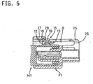
- the hooking part 14 includes a substantially vertical face at a front end thereof, and an inclined contact face 13a. Therefore, when the female housing F1 is pushed into the male housing M1, the hanging part 12 of the lock piece 8 rides over the inclined face 13a and the lock piece 8 pivots or swings in a clockwise direction (see Figure 4). When both housings M1 and F1 are properly fitted, the hanging part 12 rides over the hooking part 13 and the lock piece 8 is therefore restored to its original position, being locked by hooking the hanging part 12 over a rear face of the hooking part 13 (see Figure 5).
- a detecting member 15 is provided in the female housing F1.
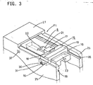
- the detecting member 15 is formed as a separate synthetic resin material piece. As shown in detail in Figure 3, the detecting member 15 is formed in a "low gate" shape and crosses over or traverses the lock piece 8. Legs 16 are formed to protrude to the outside at the lower end of the left and right side faces of detecting member 15.
- a pressure part 17 of a predetermined width protrudes at a central portion in the width direction at the front edge of the detecting member 15.
- a projection 18 is formed at an upper face of an outside edge of the pressure part 17 for hooking (as described below) and an operation part 19 extends upwardly at a rear side of the detecting member 15 at a predetermined distance from the projection 18.
- Grooves 21 formed in an upper face of lock piece 8 are about the same width as the pressure part 17 of the detecting member 15. These grooves extend from a position slightly to the front end from the central portion in the longitudinal direction to the rear end. The front edge of the grooves 21 acts as a pressure part 22.
- a pressing operation element 23 is formed at the upper face of the rear end of the lock piece 8 slightly higher than the lock piece 8, and extends in the transverse direction.
- the female housing F1 includes left and right side walls 25.
- Guide grooves 26 extend in the longitudinal direction respectively slidably to guide both legs 16 of detecting member 15 during the fitting operation.
- a roof 27 is formed at the front ends of both side walls 25 and is slightly higher than the walls.
- a rear edge of roof 27 is located just at the front edge of the lock piece 8.
- a hanging or depending part 28 is formed at the rear edge of roof 27 and is capable of fitting between the projection 18 of the detecting member 15 and the operation part 19.
- Convex elements 30 are formed at the outer face of the legs 16 of the detecting member 15.
- Rear and front hooking holes 31,32 on the left and right side walls are capable of receiving the convex elements 30.
- the rear hooking holes 31 are adapted for temporary retention and the front hooking holes 32 are adapted for proper or complete retention.
- the detecting member 15 is installed so that the legs 16 are inserted from the rear end of the corresponding guide grooves 26 when the lock piece 8 is swung to the lock cancellation direction by pressing the pressuring operation part 23, and are temporarily retained by first fitting the convex elements 30 into the rear hooking holes 31.
- the pressing operation element 23 of the lock piece 8 returns to the original position and is designed to be hooked on the rear end of the detecting member 15.
- the detecting member 15 is pushed along guide grooves 26, and reaches the upper position of the front side of lock piece 8, the convex elements 30 are thereby retained by being fitted in the front hooking holes 32.
- the hanging part 28 of the roof 27 can be fitted between the projection 18 and the operation part 19.
- the detecting member 15 is retained in advance at the temporary retention position shown in Figure 1 against the female housing F1. After the female terminals are installed in the female housing F1, the female housing F1 is pushed into the male housing M1. Thereafter, whilst the convex elements 30 are removed from the rear hooking holes 31, the detecting member 15 is pushed forwardly along the guide grooves 26.
- both housings M1 and F1 are kept in the incomplete fitting state without a proper fitting, and the hanging part 12 of the lock piece 8 swings in the clockwise direction while riding over the hooking part 13 as shown in Figure 4.
- the pressuring part 17 moves in the grooves 21 of the upper face of lock piece 8 and protrudes over the front pressured part 22 so that the incomplete fitting is thereby detected.
- the lock piece 8 along with female housing F1 is pushed in by the pressing pressure part 22.
- both housings M1 and F1 are locked by hooking the hanging part 12 on the rear face of hooking part 13, while the lock piece 8 returns to its original position.
- the detecting member 15 is further continuously pushed in so that the hanging part 28 of the roof 27 fits between the projection 18 of the detecting member 15 and the operation part 19 as shown in Figure 5, when the detecting member 15 is pushed into the predetermined position just on the front end of the lock piece 8.
- the convex elements 30 of the legs 16 fit in the front hooking holes 32 and the detecting member 15 is retained just at the position of the front end of the lock piece 8 so that unexpected raising of the front end of lock piece 8 is prevented and the connector housings are "double-locked".
- the detecting member 15 is guided along the guide grooves 26 and moved over the upper face of the lock piece 8, which has properly returned to its original position, and are retained just at the position of the front end of the lock piece 8 as described above.
- the female housing F1 By pushing the detecting member 15 in, after detecting such incomplete fitting, the female housing F1 is pushed in to the proper position and can be locked. Since the detecting member 15 can be retained at the position of the front end of the lock piece 8, the detecting member 15 can function to double lock the housings.
- the detecting member includes structure for being pushed in to the front end from the rear end of the lock piece, but it is possible to detect the incomplete fitted state when the detecting member is pushed in a transverse direction to the front side of the lock piece from the side, and this is included within the scope of the present invention.
- the present invention can also be applied to conventional lock forms as well as the "momentum-lock” as illustrated and described above.
- the present invention can also be applied to a connector with an arm-type lock piece which is installed so as to be capable of deforming by bending in the form of a cantilever, as well as the seesaw type lock piece as described above.
Landscapes
- Details Of Connecting Devices For Male And Female Coupling (AREA)
Description
- The present invention relates to a connector including first and second housings. A lock piece on one housing cooperates with a hooking part on the other housing. A detecting member indicates whether the housings are properly locked together.
- A connector using the motion of a position change of a lock piece in order to detect partial connection of connector housings has been previously proposed. An example is a lever or seesaw type lock piece having a hanging part on a front side of one connector housing. A hooking part adapted to hook the hanging part is provided on the other connector housing. When both housings are fitted together, the hanging part is mounted on the hooking part and the lock piece is pushed in as it swings about a fulcrum. When both housings are properly fitted, the lock piece returns to its original position and is locked by hooking the hanging part on the hooking part. Furthermore, a detecting member is inserted in the bottom side of a rear end of the lock piece, and when both housings are properly connected together, the lock piece returns to its original position and the detecting member can be inserted into an opening at the bottom side of the rear end part. On the other hand, when both housings are only partially fitted together, the detecting member cannot be inserted because the hanging part is mounted on the hooking part and the lock piece swings. Therefore, it is possible to detect an incomplete connection of the housing.
- However, this method has disadvantages. For example, when the lock piece is a seesaw or lever, the rear end hangs down if the hanging part on the front end is mounted on the hooking part, but the lock piece itself, which is a synthetic resin having elasticity, becomes bent and does not change its position to extend downward at the rear end. Although it may slightly change its position depending on its shape when it is mounted on the hooking part, the hanging part is kept in an incomplete fitted position or state and the detecting part is under the rear end of the lock piece so that it cannot be detected. Accordingly, this conventional method has not been reliable.
-
US-A-4946395 discloses a connector according to the prior art portion of claim 1. - The present invention provides a connector as defined in claim 1.
- Preferably, the end portion of the lock piece includes a first contact face and the hooking part includes a second contact face, and the first contact face initially contacts the second contact face and thereafter passes over the hooking part when the first and second connector housings are moved to the properly fitted position. The second contact face may be inclined.
- The lock piece may include a lever, said lever that swings about a fulcrum on the other of the first and second housing. The detecting member includes at least one projection.
- The present invention is further explained by way of example only in the description which follows with reference to the drawings wherein:
- Figure 1 is a cross section view of a connector with housings separated from each other according to a first embodiment of the present invention;
- Figure 2 is a plan view in partial cross section of the female housing of Figure 1;
- Figure 3 is a perspective view showing structure equipped with a detecting member;
- Figure 4 is a cross sectional view showing a state of detecting incomplete fitting of the housings; and
- Figure 5 is a cross sectional view of a state in which both housings are properly fitted and a detecting member is retained at the proper retaining position;
- The connector of the invention illustrated in Figures 1-5 of the accompanying drawings is a waterproof and "momentum-lock" type connector. As illustrated in Figure 1 of the drawings a male housing M1 and a female connector housing F1 are adapted to be mutually fitted together. The male housing M1 is formed from a synthetic resin and is adapted to be connected to, for example, an engine accessory or the like. The male housing M1 is of oblong rectangular shape having a bottom, an open front face, and inner concave part 1. A plurality of male terminal fittings (not shown) are arranged in and protrude from the inner concave part 1.
- The female connector housing F1 is similarly formed from a synthetic resin material. A
hood 3 of oblong rectangular shape is formed from around a front end (left side of Figure 1) of a main body part. - The male housing M1 is adapted to be fitted in the inside of the
hood 3 and in a front end of thebody part 2. - A plurality of
cavities 4 are arranged in thebody part 2 and are formed to correspond to the male terminal fittings of male housing M1. Female terminals fixed at the end of wires (not illustrated) are inserted from the rear face side thereof, and are hooked by alance 5 provided in thecavities 4 to hold such female terminals in a hooked state. Furthermore, waterproof rubber stoppers are fixed to the rear side of the respective female terminals, and the inlets of respective cavities are thereby sealed. A rubber ring 6 is provided around thebody part 2 in the inner portion of thehood 3. Both housings M1 and F1 are thereby connected together and a gap between both housings is designed to be sealed by the sealing engagement of the rubber ring 6 between thebody part 2 and theconcave part 3. - In a gap between both housings M1 and F1, a lock mechanism is provided for locking the housings in a proper fitted state. A
lock piece 8 is provided in the upper face of the female housing F1 at a central portion in the width of the female housing F1. Thelock piece 8 is long and narrow in a longitudinal direction and is formed in the shape of a "low gate" section. The lower edges of left and right side walls at approximately the central portion in the longitudinal direction are integrally connected with thebody part 2 at afulcrum 9, so thatlock piece 8 can pivot as a lever or seesaw about thefulcrum 9. Furthermore, anotch groove 10 in an upper face ofhood 3 opens at a central portion in the width to receive a front end of thelock piece 8. A hanging or dependingpart 12 is formed at a front end of thelock piece 8, and afront contact face 12a of thehanging part 12 is adapted to cooperate with a projection or hookingpart 13, formed on the outer surface of the male housing M1, as described below. The hooking part 14 is capable of cooperating with, and hooking onto, thehanging part 12 of thelock piece 8. The hooking part 14 includes a substantially vertical face at a front end thereof, and aninclined contact face 13a. Therefore, when the female housing F1 is pushed into the male housing M1, thehanging part 12 of thelock piece 8 rides over theinclined face 13a and thelock piece 8 pivots or swings in a clockwise direction (see Figure 4). When both housings M1 and F1 are properly fitted, thehanging part 12 rides over thehooking part 13 and thelock piece 8 is therefore restored to its original position, being locked by hooking thehanging part 12 over a rear face of the hooking part 13 (see Figure 5). - When the contact faces 12a and 13a of the
hanging part 12 and hookingpart 13, respectively, are formed in the shape described above, a large force is required to move thehanging part 12 over thehooking part 13. Therefore, a "momentum-lock" is formed so that if a peak force required for allowing the hangingpart 12 to ride over hookingpart 13 is set to be larger than a peak frictional force at the mutually fitted state of the male and female terminal housings, the female housing F1 will be pushed to a proper fitted position by momentum, namely by pushing the female housing in and letting thehanging part 12 of the lock piece ride over thehooking part 13. The male and female terminal fittings are thereby mutually connected, and both housings M1 and F1 are mutually locked together. - When the momentum lock is applied as described above, there is little fear that both housings M1 and F1 will be disposed in an incomplete fitted state. However when, for example, the female housing F1 is pushed so that the
lock piece 8 is moved in a cancellation direction before locking, the housings may be kept in the incomplete fitted state with hangingpart 12 oflock piece 8 being disposed on top of thehooking part 13 as shown in Figure 4. - In order to detect such an incomplete fitted state, a detecting
member 15 is provided in the female housing F1. The detectingmember 15 is formed as a separate synthetic resin material piece. As shown in detail in Figure 3, the detectingmember 15 is formed in a "low gate" shape and crosses over or traverses thelock piece 8.Legs 16 are formed to protrude to the outside at the lower end of the left and right side faces of detectingmember 15. Apressure part 17 of a predetermined width protrudes at a central portion in the width direction at the front edge of the detectingmember 15. Aprojection 18 is formed at an upper face of an outside edge of thepressure part 17 for hooking (as described below) and anoperation part 19 extends upwardly at a rear side of the detectingmember 15 at a predetermined distance from theprojection 18. -
Grooves 21 formed in an upper face oflock piece 8 are about the same width as thepressure part 17 of the detectingmember 15. These grooves extend from a position slightly to the front end from the central portion in the longitudinal direction to the rear end. The front edge of thegrooves 21 acts as apressure part 22. Apressing operation element 23 is formed at the upper face of the rear end of thelock piece 8 slightly higher than thelock piece 8, and extends in the transverse direction. - The female housing F1 includes left and
right side walls 25.Guide grooves 26 extend in the longitudinal direction respectively slidably to guide bothlegs 16 of detectingmember 15 during the fitting operation. - A
roof 27 is formed at the front ends of bothside walls 25 and is slightly higher than the walls. A rear edge ofroof 27 is located just at the front edge of thelock piece 8. A hanging or dependingpart 28 is formed at the rear edge ofroof 27 and is capable of fitting between theprojection 18 of the detectingmember 15 and theoperation part 19. -
Convex elements 30 are formed at the outer face of thelegs 16 of the detectingmember 15. Rear and front hookingholes convex elements 30. Therear hooking holes 31 are adapted for temporary retention and the front hookingholes 32 are adapted for proper or complete retention. - In particular, the detecting
member 15 is installed so that thelegs 16 are inserted from the rear end of thecorresponding guide grooves 26 when thelock piece 8 is swung to the lock cancellation direction by pressing thepressuring operation part 23, and are temporarily retained by first fitting theconvex elements 30 into the rear hooking holes 31. At this position, as shown in Figure 1. thepressing operation element 23 of thelock piece 8 returns to the original position and is designed to be hooked on the rear end of the detectingmember 15. Furthermore, when the detectingmember 15 is pushed alongguide grooves 26, and reaches the upper position of the front side oflock piece 8, theconvex elements 30 are thereby retained by being fitted in the front hooking holes 32. At the same time, the hangingpart 28 of theroof 27 can be fitted between theprojection 18 and theoperation part 19. - According to this embodiment as described above, the detecting
member 15 is retained in advance at the temporary retention position shown in Figure 1 against the female housing F1. After the female terminals are installed in the female housing F1, the female housing F1 is pushed into the male housing M1. Thereafter, whilst theconvex elements 30 are removed from therear hooking holes 31, the detectingmember 15 is pushed forwardly along theguide grooves 26. - Thereby, in the fitting operation as described above, both housings M1 and F1 are kept in the incomplete fitting state without a proper fitting, and the hanging
part 12 of thelock piece 8 swings in the clockwise direction while riding over the hookingpart 13 as shown in Figure 4. When the detectingmember 15 is pushed, the pressuringpart 17 moves in thegrooves 21 of the upper face oflock piece 8 and protrudes over the front pressuredpart 22 so that the incomplete fitting is thereby detected. - Thereafter, when the detecting
member 15 is further pushed in, thelock piece 8 along with female housing F1 is pushed in by thepressing pressure part 22. When the female housing F1 is pushed into the proper position, both housings M1 and F1 are locked by hooking the hangingpart 12 on the rear face of hookingpart 13, while thelock piece 8 returns to its original position. The detectingmember 15 is further continuously pushed in so that the hangingpart 28 of theroof 27 fits between theprojection 18 of the detectingmember 15 and theoperation part 19 as shown in Figure 5, when the detectingmember 15 is pushed into the predetermined position just on the front end of thelock piece 8. Furthermore, theconvex elements 30 of thelegs 16 fit in the front hookingholes 32 and the detectingmember 15 is retained just at the position of the front end of thelock piece 8 so that unexpected raising of the front end oflock piece 8 is prevented and the connector housings are "double-locked". - Furthermore, when both housings M1 and F1 are initially properly fitted, the detecting
member 15 is guided along theguide grooves 26 and moved over the upper face of thelock piece 8, which has properly returned to its original position, and are retained just at the position of the front end of thelock piece 8 as described above. - According to the embodiment as described above, after the female housing F1 is fitted on the male housing M1, pushing of the detecting
member 15 then is carried out, and when the housings are in the incomplete fitted state, protrusion of the detectingmember 15 provides detection of such an incomplete fitted state. Furthermore, since the detectingmember 15 protrudes beyond the front end which has changed its position when the lock piece rides over the hookingpart 13, highly reliable detection of the incomplete fitted state can be accomplished. - By pushing the detecting
member 15 in, after detecting such incomplete fitting, the female housing F1 is pushed in to the proper position and can be locked. Since the detectingmember 15 can be retained at the position of the front end of thelock piece 8, the detectingmember 15 can function to double lock the housings. - The present invention is not limited by the mode of operation illustrated according to the above descriptions and figures. For example, the following modes of operation are included within the scope of the present invention and furthermore, various changes can be practiced within such scope in addition to the following.
- In the above embodiment, the detecting member includes structure for being pushed in to the front end from the rear end of the lock piece, but it is possible to detect the incomplete fitted state when the detecting member is pushed in a transverse direction to the front side of the lock piece from the side, and this is included within the scope of the present invention.
- The present invention can also be applied to conventional lock forms as well as the "momentum-lock" as illustrated and described above.
- Furthermore, the present invention can also be applied to a connector with an arm-type lock piece which is installed so as to be capable of deforming by bending in the form of a cantilever, as well as the seesaw type lock piece as described above.
Claims (4)
- A connector comprising first and second connector housings (M1,F1) adapted to be connected together along a fitting direction between a plurality of improperly fitted positions and a properly fitted position, a hooking part (13) attached to one of the connector housings (M1), a lock piece (8) attached to the other of the connector housings (F1), the lock piece (8) including an end portion (12) for obliquely moving from an original position to pass over the hooking part (13) and being adapted to return to the original position to hook the hooking part (13) when the first and second connector housings (M1,F1) are moved in a fitting direction into the properly fitted position, a detecting member (15) movable along the other of the connector housings (F1) in the fitting direction for detecting an improperly fitted position of the first and second connector housings (M1,F1) by engagement with the lock piece (8) when the first and second connector housings (M1,F1) are in the improperly fitted position and the end portion (12) of the lock piece (8) is not in the original position, and the detecting member (15) is retained in an advanced position by engagement with the other of the connector housings (F1) to maintain engagement of the end portion (12) of the lock piece (8) with the hooking part (13) in the properly fitted position of the connector housings (M1,F1) characterised in that, when the improperly fitted position of the first and second connector housings (M1, F1) is detected, the detecting member (15) is movable in the fitting direction to push the lock piece 8 by engagement of a pressuring part (17) of the detecting member (15) with a pressured part (22) of the lock piece (8) and move the other connector housing (F1) from the improperly fitted position to the properly fitted Position in which the end portion (12) of the lock piece (8) returns to the original position to hook over the hooking part (13) to lock the first and second connector housings (M1,F1) together
- A connector according to claim 1, characterised in that the end portion (12) of the lock piece (8) includes a first contact face (12a), and the hooking part (13) includes a second contact face (13a), the first contact face (12a) initially contacting the second contact face (13a) to obliquely move the end portion (12) of the lock piece (8) to pass over the hooking part (13) when the first and second connector housings (M1,F1) are moved to the properly fitted position.
- A connector according to claim 2, characterised in that the second contact face (13a) is inclined.
- A connector according to any preceding claim, characterised in that the lock piece (8) comprises a lever, the lever swinging about a fulcrum (9) on the other of the connector housings (F1).
Priority Applications (2)
| Application Number | Priority Date | Filing Date | Title |
|---|---|---|---|
| EP07012114A EP1833124A3 (en) | 1996-07-23 | 1997-07-18 | Electrical connector |
| EP07012071A EP1837958A1 (en) | 1996-07-23 | 1997-07-18 | Electrical connector |
Applications Claiming Priority (2)
| Application Number | Priority Date | Filing Date | Title |
|---|---|---|---|
| JP19369096A JP3235478B2 (en) | 1996-07-23 | 1996-07-23 | connector |
| JP193690/96 | 1996-07-23 |
Related Child Applications (2)
| Application Number | Title | Priority Date | Filing Date |
|---|---|---|---|
| EP07012114A Division EP1833124A3 (en) | 1996-07-23 | 1997-07-18 | Electrical connector |
| EP07012071A Division EP1837958A1 (en) | 1996-07-23 | 1997-07-18 | Electrical connector |
Publications (3)
| Publication Number | Publication Date |
|---|---|
| EP0821441A2 EP0821441A2 (en) | 1998-01-28 |
| EP0821441A3 EP0821441A3 (en) | 1999-04-07 |
| EP0821441B1 true EP0821441B1 (en) | 2007-10-24 |
Family
ID=16312167
Family Applications (3)
| Application Number | Title | Priority Date | Filing Date |
|---|---|---|---|
| EP07012071A Withdrawn EP1837958A1 (en) | 1996-07-23 | 1997-07-18 | Electrical connector |
| EP07012114A Withdrawn EP1833124A3 (en) | 1996-07-23 | 1997-07-18 | Electrical connector |
| EP97305398A Expired - Lifetime EP0821441B1 (en) | 1996-07-23 | 1997-07-18 | Electrical connector |
Family Applications Before (2)
| Application Number | Title | Priority Date | Filing Date |
|---|---|---|---|
| EP07012071A Withdrawn EP1837958A1 (en) | 1996-07-23 | 1997-07-18 | Electrical connector |
| EP07012114A Withdrawn EP1833124A3 (en) | 1996-07-23 | 1997-07-18 | Electrical connector |
Country Status (5)
| Country | Link |
|---|---|
| US (1) | US6024595A (en) |
| EP (3) | EP1837958A1 (en) |
| JP (1) | JP3235478B2 (en) |
| CN (1) | CN1068977C (en) |
| DE (1) | DE69738230T2 (en) |
Families Citing this family (44)
| Publication number | Priority date | Publication date | Assignee | Title |
|---|---|---|---|---|
| JP3235478B2 (en) * | 1996-07-23 | 2001-12-04 | 住友電装株式会社 | connector |
| EP0933835B1 (en) * | 1998-02-03 | 2003-09-10 | The Whitaker Corporation | Electrical connector |
| JP2001085111A (en) * | 1999-09-10 | 2001-03-30 | Sumitomo Wiring Syst Ltd | Connector |
| JP3419715B2 (en) * | 1999-10-14 | 2003-06-23 | 株式会社オートネットワーク技術研究所 | Lock mechanism in connector |
| JP3349484B2 (en) * | 1999-11-09 | 2002-11-25 | 住友電装株式会社 | Detachment detection system for joints |
| US6273741B1 (en) * | 2000-01-14 | 2001-08-14 | Daimlerchrysler Corporation | Locking connector for antenna cable |
| JP2001291557A (en) * | 2000-04-06 | 2001-10-19 | Sumitomo Wiring Syst Ltd | Connector |
| JP3958525B2 (en) * | 2001-02-27 | 2007-08-15 | 矢崎総業株式会社 | Connector mating detection structure |
| JP3920055B2 (en) | 2001-04-12 | 2007-05-30 | 矢崎総業株式会社 | Method of assembling half-fitting prevention connector and half-fitting prevention connector |
| JP3810285B2 (en) * | 2001-06-12 | 2006-08-16 | 矢崎総業株式会社 | Half-mating prevention connector |
| CN100336271C (en) * | 2002-05-24 | 2007-09-05 | 西安富士达科技有限责任公司 | Small type push in self locking precise stationary phase connector |
| JP3903885B2 (en) * | 2002-09-02 | 2007-04-11 | 住友電装株式会社 | Connector with detection member |
| DE602004032354D1 (en) * | 2003-06-18 | 2011-06-01 | Framatome Connectors Int | ELECTRICAL CONNECTOR |
| DE102004049333B4 (en) * | 2004-10-09 | 2007-03-08 | Hirschmann Automotive Gmbh | Connectors for use in vehicles |
| JP4770346B2 (en) * | 2005-09-13 | 2011-09-14 | 住友電装株式会社 | connector |
| DE102006023471B4 (en) * | 2006-05-18 | 2011-12-29 | Continental Automotive Gmbh | Device housing, in particular for a sensor for motor vehicles |
| JP4968793B2 (en) * | 2006-12-01 | 2012-07-04 | タイコエレクトロニクスジャパン合同会社 | Electrical connector assembly |
| WO2008066149A1 (en) * | 2006-12-01 | 2008-06-05 | Tyco Electronics Amp K.K. | Electric connector assembly |
| JP2008192517A (en) * | 2007-02-06 | 2008-08-21 | Tyco Electronics Amp Kk | Electric connector assembly |
| US7892014B2 (en) * | 2007-04-04 | 2011-02-22 | John Mezzalingua Associates, Inc. | Releasably engaging high definition multimedia interface plug |
| JP4911712B2 (en) * | 2007-04-10 | 2012-04-04 | タイコエレクトロニクスジャパン合同会社 | Electrical connector assembly |
| KR100858729B1 (en) * | 2007-06-27 | 2008-09-17 | 한국단자공업 주식회사 | Connector housing |
| DE102010024206B4 (en) * | 2009-07-08 | 2015-08-20 | Sumitomo Wiring Systems, Ltd. | Connector and connector with connector |
| JP2011049074A (en) * | 2009-08-27 | 2011-03-10 | Create Pro:Kk | Connector device |
| JP5511464B2 (en) * | 2010-03-26 | 2014-06-04 | 矢崎総業株式会社 | Board connection connector fitting confirmation structure |
| JP2014123466A (en) * | 2012-12-20 | 2014-07-03 | Sumitomo Wiring Syst Ltd | Connector |
| US9160095B2 (en) * | 2013-02-28 | 2015-10-13 | Yazaki North America, Inc. | Connector assembly with connector position assurance stabilizer |
| KR101491270B1 (en) * | 2013-07-05 | 2015-02-06 | 현대자동차주식회사 | High voltage connector |
| JP2015079710A (en) * | 2013-10-18 | 2015-04-23 | 住友電装株式会社 | Connector |
| US8968021B1 (en) | 2013-12-11 | 2015-03-03 | JAE Oregon, Inc. | Self-rejecting automotive harness connector |
| US9356394B2 (en) | 2013-12-11 | 2016-05-31 | JAE Oregon, Inc. | Self-rejecting connector |
| JP6347228B2 (en) * | 2015-05-11 | 2018-06-27 | 住友電装株式会社 | connector |
| EP3252880B1 (en) * | 2016-06-02 | 2020-05-20 | Aptiv Technologies Limited | Electrical connector assembly with improved locking device |
| JP6850477B2 (en) * | 2017-04-24 | 2021-03-31 | 日本圧着端子製造株式会社 | Electrical connector with lock mechanism |
| US10855025B2 (en) * | 2017-05-01 | 2020-12-01 | J.S.T. Corporation | Connector position assurance device, connector system and method for operating the connector system |
| US9929509B1 (en) * | 2017-06-12 | 2018-03-27 | Delphi Technologies, Inc. | Connector system with low profile connector position assurance device |
| CN107448692A (en) * | 2017-09-01 | 2017-12-08 | 特百科汽车工业(宁波)有限公司 | A kind of fluid line and the device for being provided with the fluid line |
| US10109950B1 (en) * | 2017-09-13 | 2018-10-23 | Delphi Technologies, Inc. | High vibration connector with a connector-position-assurance device |
| CN108417443B (en) * | 2018-04-09 | 2020-06-02 | 金陵科技学院 | A kind of railway relay base locking method |
| JP2020080271A (en) * | 2018-11-14 | 2020-05-28 | 住友電装株式会社 | connector |
| JP2021005518A (en) * | 2019-06-27 | 2021-01-14 | 住友電装株式会社 | connector |
| EP3886264B1 (en) * | 2020-03-27 | 2023-11-08 | Aptiv Technologies Limited | Sealed electrical connector |
| US20240258745A1 (en) * | 2021-05-18 | 2024-08-01 | Phoenix Contact Asia-Pacific (Nanjing) Co., Ltd. | Connector outer housing |
| US12413026B2 (en) * | 2022-12-19 | 2025-09-09 | GM Global Technology Operations LLC | Monitoring the position of an electrical connector |
Citations (2)
| Publication number | Priority date | Publication date | Assignee | Title |
|---|---|---|---|---|
| US4708413A (en) * | 1986-03-21 | 1987-11-24 | General Motors Corporation | Electrical connector with position assurance and assist |
| JPH03285280A (en) * | 1990-03-01 | 1991-12-16 | Yazaki Corp | Lock confirmation device of electric connector |
Family Cites Families (16)
| Publication number | Priority date | Publication date | Assignee | Title |
|---|---|---|---|---|
| US4634204A (en) | 1985-12-24 | 1987-01-06 | General Motors Corporation | Electrical connector with connector position assurance/assist device |
| US4946395A (en) * | 1989-07-17 | 1990-08-07 | General Motors Corporation | Electrical connector with connector position assurance device |
| US5120255A (en) * | 1990-03-01 | 1992-06-09 | Yazaki Corporation | Complete locking confirming device for confirming the complete locking of an electric connector |
| JPH0770340B2 (en) * | 1990-03-27 | 1995-07-31 | 矢崎総業株式会社 | Connector coupling detector |
| JPH0466784A (en) * | 1990-07-06 | 1992-03-03 | Seiko Epson Corp | Micropump and its manufacturing method |
| JPH0472573A (en) * | 1990-07-13 | 1992-03-06 | Komatsu Ltd | Rotation speed detection device |
| JP2563323Y2 (en) | 1990-10-22 | 1998-02-18 | 矢崎総業株式会社 | connector |
| US5199902A (en) * | 1991-12-23 | 1993-04-06 | Gte Products Corporation | Connector device |
| JP2727869B2 (en) * | 1992-05-29 | 1998-03-18 | 住友電装株式会社 | Body fixing connector |
| JPH0650268U (en) * | 1992-12-07 | 1994-07-08 | 住友電装株式会社 | connector |
| US5507666A (en) * | 1993-12-28 | 1996-04-16 | Yazaki Corporation | Lock securing mechanism for connectors |
| JP2921645B2 (en) | 1994-07-12 | 1999-07-19 | 矢崎総業株式会社 | Connector mating detection structure |
| DE69415164T2 (en) * | 1994-10-10 | 1999-10-28 | Molex Inc., Lisle | Electrical connector with position securing system. |
| US5605471A (en) * | 1995-02-01 | 1997-02-25 | United Technologies Automotive, Inc. | Electrical connector assembly employing a connector position assurance device |
| US5720623A (en) * | 1996-06-10 | 1998-02-24 | General Motors Corporation | Position assurance electrical connector |
| JP3235478B2 (en) * | 1996-07-23 | 2001-12-04 | 住友電装株式会社 | connector |
-
1996
- 1996-07-23 JP JP19369096A patent/JP3235478B2/en not_active Expired - Fee Related
-
1997
- 1997-07-16 CN CN97114683A patent/CN1068977C/en not_active Expired - Fee Related
- 1997-07-18 DE DE69738230T patent/DE69738230T2/en not_active Expired - Lifetime
- 1997-07-18 EP EP07012071A patent/EP1837958A1/en not_active Withdrawn
- 1997-07-18 EP EP07012114A patent/EP1833124A3/en not_active Withdrawn
- 1997-07-18 EP EP97305398A patent/EP0821441B1/en not_active Expired - Lifetime
- 1997-07-23 US US08/899,141 patent/US6024595A/en not_active Expired - Lifetime
Patent Citations (2)
| Publication number | Priority date | Publication date | Assignee | Title |
|---|---|---|---|---|
| US4708413A (en) * | 1986-03-21 | 1987-11-24 | General Motors Corporation | Electrical connector with position assurance and assist |
| JPH03285280A (en) * | 1990-03-01 | 1991-12-16 | Yazaki Corp | Lock confirmation device of electric connector |
Also Published As
| Publication number | Publication date |
|---|---|
| CN1171642A (en) | 1998-01-28 |
| DE69738230D1 (en) | 2007-12-06 |
| CN1068977C (en) | 2001-07-25 |
| US6024595A (en) | 2000-02-15 |
| JP3235478B2 (en) | 2001-12-04 |
| EP0821441A2 (en) | 1998-01-28 |
| EP1833124A3 (en) | 2009-01-14 |
| EP1833124A2 (en) | 2007-09-12 |
| DE69738230T2 (en) | 2008-07-31 |
| EP1837958A1 (en) | 2007-09-26 |
| JPH1041017A (en) | 1998-02-13 |
| EP0821441A3 (en) | 1999-04-07 |
Similar Documents
| Publication | Publication Date | Title |
|---|---|---|
| US6024595A (en) | Connector | |
| US5803651A (en) | Double locking connector | |
| US6332800B2 (en) | Connector assembly having inertia locking mechanism | |
| EP0841724B1 (en) | A connector | |
| JP3685290B2 (en) | connector | |
| US6059598A (en) | Connector | |
| US5104330A (en) | Electric connector | |
| US5827086A (en) | Half-fitting prevention connector | |
| EP0734100B1 (en) | Electrical connector with terminal position assurance | |
| EP1089393B1 (en) | A connector | |
| US6494732B2 (en) | Connector fitting structure | |
| US6102726A (en) | Connector fitting structure | |
| US5928011A (en) | Slide lock position assurance and release lever | |
| EP1176676B1 (en) | Connector fitting structure | |
| US5529512A (en) | Connector with low insertion force | |
| US5088938A (en) | Terminal locking block for electrical connectors | |
| US9048574B2 (en) | Spring lock connector | |
| JP2600796Y2 (en) | Arm connection type connector | |
| EP0923169A1 (en) | Connector containing a short-circuit terminal | |
| JPH0690940B2 (en) | Electrical connector with double locking structure for terminal fittings | |
| US7270553B2 (en) | Pivotal lever-type connector | |
| JP3928491B2 (en) | connector | |
| CN1226757A (en) | Connector | |
| US5464351A (en) | Branch joint box | |
| US20050002734A1 (en) | Connector |
Legal Events
| Date | Code | Title | Description |
|---|---|---|---|
| PUAI | Public reference made under article 153(3) epc to a published international application that has entered the european phase |
Free format text: ORIGINAL CODE: 0009012 |
|
| 17P | Request for examination filed |
Effective date: 19970809 |
|
| AK | Designated contracting states |
Kind code of ref document: A2 Designated state(s): DE ES FR GB IT PT |
|
| AX | Request for extension of the european patent |
Free format text: AL;LT;LV;RO;SI |
|
| PUAL | Search report despatched |
Free format text: ORIGINAL CODE: 0009013 |
|
| AK | Designated contracting states |
Kind code of ref document: A3 Designated state(s): AT BE CH DE DK ES FI FR GB GR IE IT LI LU MC NL PT SE |
|
| AX | Request for extension of the european patent |
Free format text: AL;LT;LV;RO;SI |
|
| AKX | Designation fees paid |
Free format text: DE ES FR GB IT PT |
|
| TPAD | Observations filed by third parties |
Free format text: ORIGINAL CODE: EPIDOS TIPA |
|
| 17Q | First examination report despatched |
Effective date: 20051017 |
|
| GRAP | Despatch of communication of intention to grant a patent |
Free format text: ORIGINAL CODE: EPIDOSNIGR1 |
|
| RIN1 | Information on inventor provided before grant (corrected) |
Inventor name: OSAWA, HIROKIC/O SUMITOMO WIRING SYSTEMS, LTD. Inventor name: SABA, TOSHIKAZUC/O SUMITOMO WIRING SYSTEMS, LTD. |
|
| GRAS | Grant fee paid |
Free format text: ORIGINAL CODE: EPIDOSNIGR3 |
|
| GRAA | (expected) grant |
Free format text: ORIGINAL CODE: 0009210 |
|
| AK | Designated contracting states |
Kind code of ref document: B1 Designated state(s): DE ES FR GB IT PT |
|
| REG | Reference to a national code |
Ref country code: GB Ref legal event code: FG4D |
|
| REF | Corresponds to: |
Ref document number: 69738230 Country of ref document: DE Date of ref document: 20071206 Kind code of ref document: P |
|
| ET | Fr: translation filed | ||
| PG25 | Lapsed in a contracting state [announced via postgrant information from national office to epo] |
Ref country code: ES Free format text: LAPSE BECAUSE OF FAILURE TO SUBMIT A TRANSLATION OF THE DESCRIPTION OR TO PAY THE FEE WITHIN THE PRESCRIBED TIME-LIMIT Effective date: 20080204 |
|
| PG25 | Lapsed in a contracting state [announced via postgrant information from national office to epo] |
Ref country code: PT Free format text: LAPSE BECAUSE OF FAILURE TO SUBMIT A TRANSLATION OF THE DESCRIPTION OR TO PAY THE FEE WITHIN THE PRESCRIBED TIME-LIMIT Effective date: 20080324 |
|
| PLBE | No opposition filed within time limit |
Free format text: ORIGINAL CODE: 0009261 |
|
| STAA | Information on the status of an ep patent application or granted ep patent |
Free format text: STATUS: NO OPPOSITION FILED WITHIN TIME LIMIT |
|
| 26N | No opposition filed |
Effective date: 20080725 |
|
| PGFP | Annual fee paid to national office [announced via postgrant information from national office to epo] |
Ref country code: IT Payment date: 20130620 Year of fee payment: 17 |
|
| PGFP | Annual fee paid to national office [announced via postgrant information from national office to epo] |
Ref country code: DE Payment date: 20130711 Year of fee payment: 17 |
|
| PGFP | Annual fee paid to national office [announced via postgrant information from national office to epo] |
Ref country code: GB Payment date: 20130717 Year of fee payment: 17 Ref country code: FR Payment date: 20130724 Year of fee payment: 17 |
|
| REG | Reference to a national code |
Ref country code: DE Ref legal event code: R119 Ref document number: 69738230 Country of ref document: DE |
|
| GBPC | Gb: european patent ceased through non-payment of renewal fee |
Effective date: 20140718 |
|
| REG | Reference to a national code |
Ref country code: FR Ref legal event code: ST Effective date: 20150331 |
|
| PG25 | Lapsed in a contracting state [announced via postgrant information from national office to epo] |
Ref country code: DE Free format text: LAPSE BECAUSE OF NON-PAYMENT OF DUE FEES Effective date: 20150203 Ref country code: IT Free format text: LAPSE BECAUSE OF NON-PAYMENT OF DUE FEES Effective date: 20140718 |
|
| REG | Reference to a national code |
Ref country code: DE Ref legal event code: R119 Ref document number: 69738230 Country of ref document: DE Effective date: 20150203 |
|
| PG25 | Lapsed in a contracting state [announced via postgrant information from national office to epo] |
Ref country code: FR Free format text: LAPSE BECAUSE OF NON-PAYMENT OF DUE FEES Effective date: 20140731 Ref country code: GB Free format text: LAPSE BECAUSE OF NON-PAYMENT OF DUE FEES Effective date: 20140718 |