EP0820902B1 - Clamping device for a cycle - Google Patents
Clamping device for a cycle Download PDFInfo
- Publication number
- EP0820902B1 EP0820902B1 EP97202084A EP97202084A EP0820902B1 EP 0820902 B1 EP0820902 B1 EP 0820902B1 EP 97202084 A EP97202084 A EP 97202084A EP 97202084 A EP97202084 A EP 97202084A EP 0820902 B1 EP0820902 B1 EP 0820902B1
- Authority
- EP
- European Patent Office
- Prior art keywords
- support body
- clamping device
- cycle
- post
- crank
- Prior art date
- Legal status (The legal status is an assumption and is not a legal conclusion. Google has not performed a legal analysis and makes no representation as to the accuracy of the status listed.)
- Expired - Lifetime
Links
Images


Classifications
-
- B—PERFORMING OPERATIONS; TRANSPORTING
- B60—VEHICLES IN GENERAL
- B60R—VEHICLES, VEHICLE FITTINGS, OR VEHICLE PARTS, NOT OTHERWISE PROVIDED FOR
- B60R9/00—Supplementary fittings on vehicle exterior for carrying loads, e.g. luggage, sports gear or the like
- B60R9/08—Supplementary fittings on vehicle exterior for carrying loads, e.g. luggage, sports gear or the like specially adapted for sports gear
- B60R9/10—Supplementary fittings on vehicle exterior for carrying loads, e.g. luggage, sports gear or the like specially adapted for sports gear for cycles
Definitions
- the invention relates to a clamping device for a cycle comprising a vertically placeable post which is provided with clamping means for clamping a crank of a cycle.
- This clamping device is intended for instance for use in a cycle parking area, on the roof construction of an automobile or on a removable cycle carrier which can be fixed to the tow hook of an automobile.
- Such a clamping device is known from the European patent application publication EP-A-0 666 197.
- the clamping device known from this publication comprises a post for fixing to a central beam of a cycle carrier, on which post is mounted an axially symmetrical clamp, the clamping parts of which take a clothes peg-like form, wherein a broad functional end and a narrowing tail end are always mutually connected for securing two cycles by clamping a crank thereof.
- the known clamping device is applied in combination with U-shaped receiving channels for the wheels of a cycle in a manner such that the weight of a cycle presses on these receiving channels and movements of this cycle in its longitudinal direction are prevented by an inclining position of the receiving channels, while movements of the cycle in transverse direction are blocked by the clamping parts round the crank.
- the clamping parts of the known clamping device are in principle only suitable for clamping cranks which lie at the same angle (for traditional types of cycle a right angle) to the crank axle.
- a clamping device for clamping a crank lying at a right angle to a crank axle is in principle not suitable, or in any case less suitable, for clamping a crank which extends slightly outward from the crank axle to the pedal, this being the case in particular types of sport and touring cycles.
- clamping device of the type stated in the preamble, of which clamping device the clamping means according to the invention comprise a support body for allowing a crank axle housing of a cycle to rest thereon and for allowing a crank of this cycle to support thereagainst, the support body being tiltable relative to the post on a shaft extending transversely of the longitudinal direction of the post.
- the clamping device exhibits the advantage over the prior art device, in that the crank of the relevant cycle supports against the support body, which thus contributes in large measure to the stability of a clamped cycle.
- the option of tilting the support body optimizes connection thereof to the relevant crank of the cycle.
- the tilting shaft is for instance formed by a solid rod or is defined for instance by the connecting line between points on which the support body is rotatably suspended.
- An embodiment of the clamping device according to the invention is provided with locking means for locking a tiltable support body against tilting.
- Such locking means are applied for instance after an optimal connection of a crank to the support body has been effected to enhance the stability of a cycle clamped with its crank in the clamping device.
- the clamping means preferably comprise coupling means for releasable coupling of the crank of a cycle to the support body, which coupling means are more preferably tiltable relative to the post on a shaft extending transversely of the longitudinal direction of the post.
- the option of tilting of the coupling means contributes to an optimal connection of the support body to the relevant crank of the cycle and thereby to the stability of a clamped cycle.
- the clamping device according to the invention is provided with height-adjusting means for height adjustment of the support body so that for any cycle for clamping the support body can be set at a height which results in an optimum stability for the cycle in question.
- the post has a U-shaped cross section and the support body is incorporated in the post.
- the post has a U-shaped cross section and the support body is arranged tiltably round a shaft extending through the two legs of this U-shape.
- This latter embodiment comprises for instance a wedge-shaped body displaceable in lengthwise direction of the post between the support body and the connecting leg of the U-shape in order to lock the support body against tilting.
- the clamping device with U-shaped post comprises in yet another embodiment a releasable coupling element anchorable to the legs of the U-shape for releasable coupling of the crank of a cycle to the support body, which coupling element comprises for instance a rigid bracket provided with screw means or a spring construction for pressing respectively pressing under spring tension onto the support body a cycle crank enclosed by this bracket respectively by this spring construction and this support body.
- a clamping device with a cross-sectionally U-shaped post comprises for instance at least two holes mutually separated at corresponding positions in longitudinal direction in each of both legs of the U-shape for receiving a pin fitting in a corresponding hole in the support body.
- the support body in a vertically placed post is preferably provided on its top with a groove for receiving a crank axle housing, which groove extends transversely of a tilting shaft of the support body and corresponds substantially with the peripheral shape of a crank axle housing of a cycle.
- the support body in a vertically placed post is provided on its standing side remote from this post with at least one groove for receiving a crank, which groove extends transversely of a tilting shaft of the support body and corresponds substantially with the peripheral shape of a cycle crank.
- the support body is advantageously manufactured from plastic, for instance polytetrafluoroethylene (PTFE) or polyamide (PA).
- PTFE polytetrafluoroethylene
- PA polyamide
- a support body manufactured from plastic prevents damage to a cycle clamped in the clamping device, can be produced in inexpensive manner and is durable in use.
- the danger of damage to a clamped cycle, particularly of the lacquer, the cables and the brake lines thereof, is reduced when the support body is wholly or partially lined with rubber or a thermoplastic elastomer (TPE).
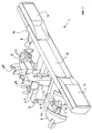
- Fig. 1 shows a removable cycle carrier 1 which is formed by a central beam 2, on the rear side of which extends a cross beam (not shown), and a platform 4 for bearing clamping devices 5a, 5b. Extending from platform 4 are hollow side arms 6 into which are pushed adjustable extension pieces 7 which each bear a wheel channel 8 on their free end. Wheel channels 8 are tiltable on a transverse shaft and displaceable over a limited distance parallel to central beam 2.
- Carrier 1 is further provided with means 3 to couple the carrier on the front part 9 of central beam 2 to the tow hook of an automobile.
- To the rear of the cross beam is fixed a light fitting 10 into which are integrated the lights 11 required for an automobile and a registration plate 12.
- a first cycle is fixed transversely of the central beam 2 onto carrier 1 by allowing this cycle to rest with its crank axle housing on the upper part of the front clamping device 5b while the extension pieces 7 are retracted and by subsequently clamping the crank of the cycle directed toward the rear part of carrier 1 into the clamping device 5b.
- the extension pieces 7 can be extended until the tiltable wheel channels 8 butt against the respective cycle wheels, whereafter extension pieces 7 can be secured in side arms 6 with locking screws 13.
- Wheel channels 8 impart extra stability to a clamped cycle, which is particularly useful when the automobile is moving and dynamic forces are being exerted on a clamped cycle.
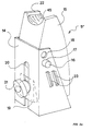
- Fig. 2a shows the clamping device 5a of fig. 1 in detail, with a U-shaped post 14 in which a support body 15 is suspended tiltably on a removable shaft 16 which, depending on the desired height of support body 15, extends through one of two pairs of holes 17 or 18 mutually separated in longitudinal direction in the legs of the U-shape.
- the position of support body 15 relative to post 14 is adjustable within a determined range using a wedge 19 (shown with dashed lines) displaceable in vertical direction between support body 15 and post 14, wherein wedge 19 can be fixed against post 14 using a wing screw 21 which extends through a lengthwise slot 20 in post 14.
- Support body 15 is provided on its top with a groove 22 extending transversely of the tilting shaft 16 for receiving a crank axle housing of a cycle, wherein the form of groove 22 corresponds with that of such a crank axle housing.
- the groove 22 is lined with a cushion 45 of rubber or a thermoplastic elastomer (TPE).
- TPE thermoplastic elastomer
- the figure further shows a receiving element 23 connected to a leg of the U-shape, the significance of which will be discussed hereinbelow.
- Fig. 2b shows the clamping device 5b of fig. 1 in detail. This is identical to clamping device 5a of fig. 2a rotated through an angle of 180° on its longitudinal axis. Shown is how support body 15 is further provided on its side remote from post 14 with grooves 24 extending transversely of the tilting shaft 16 for receiving a cycle crank, wherein the form of grooves 24 corresponds with that of such a crank.
- the coupling between the corresponding receiving elements 23 and 26 can be implemented in different ways, for instance as tiltable coupling, wherein the tilting of bracket 25 is determined by the tilting of support body 15.
- a crank enclosed in this manner can be fixed using a screw 27 in a hole in bracket 25 provided with screw thread, wherein to prevent damage to the crank the screw 27 presses a non-co-rotating contact plate (not shown) lined for instance with rubber or a TPE onto the crank.
- Fig. 3 shows a second embodiment of a clamping device 32b according to the invention with a U-shaped post 14 as seen on the open side of the U-shape.
- Clamping device 32b differs from clamping device 5b of fig. 2b in the presence of a clamp fastener 35 instead of a U-shaped bracket 25 for fixing of a cycle crank resting in groove 24.
- Fig. 4 shows in exploded view the clamp fastener 35 of fig. 3 with cup-shaped button 36 in which is received a shaft 37 which extends through a pair of holes 38.
- a resilient L-shaped bracket 39 is formed on its one outer end 40 round shaft 37 and is bent on its other outer end 41.
- Clamp fastener 35 is fixed with its bent end 41 in a slot (not shown) in a side of post 14.
- a V-shaped bracket 43 is fixed in a second pair of holes 42 in button 36 in a manner such that the end of the V-shape can be pressed round the shaft end 23 on post 14, whereafter a cycle crank enclosed by support body 15 and clamp fastener 35 can be fixed by pressing button 36 onto bracket 39, wherein button 36 rotates on axis 38 and the combination of brackets 39, 43 is tensioned.
- a plastic block 44 on bracket 39 serves to prevent damage to the cycle crank.
- Fig. 5 shows in detail the wheel channel 8 of cycle carrier 1 of fig. 1, with a bottom surface 46 from which stand side surfaces 47. Formed in side surfaces 47 are recesses 48 from which webs 49, which are provided with holes 50, extend downward.
- An extension piece 7 of a side arm 6 of cycle carrier 1 provided with corresponding holes 51 is arranged between the webs 49, wherein the distance between webs 49 is greater than the width of extension piece 7.
- the wheel channel can be fixed in per se known manner to the extension piece, for instance with a pin (not shown) through holes 50, 51, wherein the position of wheel channel 8 relative to extension piece 7 can be adjusted, for instance with intermediate rings on the pin.
- the webs 49 are provided on their underside with slots 52.
- Fig. 6 shows wheel channel 8 of fig. 5, which channel is fixed with a pin 54 to extension piece 7, in the situation where a wheel 53 of a cycle is placed in the channel. Wheel 53 is secured in channel 8 using a strap 55 which is guided through the slots 52 in webs 49 over the wheel 53 via recesses 48 and which is closed with a clasp 56.
Landscapes
- Engineering & Computer Science (AREA)
- Mechanical Engineering (AREA)
- Axle Suspensions And Sidecars For Cycles (AREA)
- Automatic Cycles, And Cycles In General (AREA)
- Clamps And Clips (AREA)
- Fittings On The Vehicle Exterior For Carrying Loads, And Devices For Holding Or Mounting Articles (AREA)
Abstract
Description
- The invention relates to a clamping device for a cycle comprising a vertically placeable post which is provided with clamping means for clamping a crank of a cycle.
- This clamping device is intended for instance for use in a cycle parking area, on the roof construction of an automobile or on a removable cycle carrier which can be fixed to the tow hook of an automobile.
- Such a clamping device is known from the European patent application publication EP-A-0 666 197. The clamping device known from this publication comprises a post for fixing to a central beam of a cycle carrier, on which post is mounted an axially symmetrical clamp, the clamping parts of which take a clothes peg-like form, wherein a broad functional end and a narrowing tail end are always mutually connected for securing two cycles by clamping a crank thereof.
- The known clamping device is applied in combination with U-shaped receiving channels for the wheels of a cycle in a manner such that the weight of a cycle presses on these receiving channels and movements of this cycle in its longitudinal direction are prevented by an inclining position of the receiving channels, while movements of the cycle in transverse direction are blocked by the clamping parts round the crank. The clamping parts of the known clamping device are in principle only suitable for clamping cranks which lie at the same angle (for traditional types of cycle a right angle) to the crank axle. A clamping device for clamping a crank lying at a right angle to a crank axle is in principle not suitable, or in any case less suitable, for clamping a crank which extends slightly outward from the crank axle to the pedal, this being the case in particular types of sport and touring cycles.
- It is an object of the invention to provide a clamping device for a cycle such that the weight of a cycle clamped therewith is supported substantially by the post.
- It is also an object to provide a clamping device which is suitable for clamping any type of cycle irrespective of the form of the crank of this cycle.
- It is a further object to provide a clamping device which is simple to operate and with which clamping can be performed in rapid manner and the use of which does not result in damage to a clamped cycle, particularly to the crank or the lacquered frame parts thereof.
- These and other objectives are achieved with a clamping device of the type stated in the preamble, of which clamping device the clamping means according to the invention comprise a support body for allowing a crank axle housing of a cycle to rest thereon and for allowing a crank of this cycle to support thereagainst, the support body being tiltable relative to the post on a shaft extending transversely of the longitudinal direction of the post.
- With the support body is achieved that the weight of a cycle resting thereon with its crank axle housing is supported substantially by the post. The clamping device according to the invention exhibits the advantage over the prior art device, in that the crank of the relevant cycle supports against the support body, which thus contributes in large measure to the stability of a clamped cycle. Moreover, the option of tilting the support body optimizes connection thereof to the relevant crank of the cycle. The tilting shaft is for instance formed by a solid rod or is defined for instance by the connecting line between points on which the support body is rotatably suspended.
- An embodiment of the clamping device according to the invention is provided with locking means for locking a tiltable support body against tilting.
- Such locking means are applied for instance after an optimal connection of a crank to the support body has been effected to enhance the stability of a cycle clamped with its crank in the clamping device.
- In a clamping device the clamping means according to the invention preferably comprise coupling means for releasable coupling of the crank of a cycle to the support body, which coupling means are more preferably tiltable relative to the post on a shaft extending transversely of the longitudinal direction of the post.
- The option of tilting of the coupling means contributes to an optimal connection of the support body to the relevant crank of the cycle and thereby to the stability of a clamped cycle.
- In an advantageous embodiment the clamping device according to the invention is provided with height-adjusting means for height adjustment of the support body so that for any cycle for clamping the support body can be set at a height which results in an optimum stability for the cycle in question.
- In an embodiment of the invention the post has a U-shaped cross section and the support body is incorporated in the post.
- In preference the post has a U-shaped cross section and the support body is arranged tiltably round a shaft extending through the two legs of this U-shape.
- This latter embodiment comprises for instance a wedge-shaped body displaceable in lengthwise direction of the post between the support body and the connecting leg of the U-shape in order to lock the support body against tilting.
- The clamping device with U-shaped post comprises in yet another embodiment a releasable coupling element anchorable to the legs of the U-shape for releasable coupling of the crank of a cycle to the support body, which coupling element comprises for instance a rigid bracket provided with screw means or a spring construction for pressing respectively pressing under spring tension onto the support body a cycle crank enclosed by this bracket respectively by this spring construction and this support body.
- For height-adjustment of the support body a clamping device with a cross-sectionally U-shaped post according to the invention comprises for instance at least two holes mutually separated at corresponding positions in longitudinal direction in each of both legs of the U-shape for receiving a pin fitting in a corresponding hole in the support body.
- In order to enhance optimum stability of a cycle clamped in the clamping device the support body in a vertically placed post is preferably provided on its top with a groove for receiving a crank axle housing, which groove extends transversely of a tilting shaft of the support body and corresponds substantially with the peripheral shape of a crank axle housing of a cycle.
- More preferably the support body in a vertically placed post is provided on its standing side remote from this post with at least one groove for receiving a crank, which groove extends transversely of a tilting shaft of the support body and corresponds substantially with the peripheral shape of a cycle crank.
- The support body is advantageously manufactured from plastic, for instance polytetrafluoroethylene (PTFE) or polyamide (PA).
- A support body manufactured from plastic prevents damage to a cycle clamped in the clamping device, can be produced in inexpensive manner and is durable in use. The danger of damage to a clamped cycle, particularly of the lacquer, the cables and the brake lines thereof, is reduced when the support body is wholly or partially lined with rubber or a thermoplastic elastomer (TPE).
- The invention will now be elucidated hereinbelow on the basis of embodiments and with reference to the annexed drawings.
- In the drawings:
- Fig. 1 shows in perspective view a simplified outline of a removable cycle carrier for an automobile provided with clamping devices according to the invention, Fig. 2a shows in perspective view a first embodiment of a clamping device according to the invention with a U-shaped post, as seen on the closed side of the U-shape,
- Fig. 2b shows in perspective view the clamping device of fig. 2a, as seen on the open side of the U-shape,
- Fig. 3 shows in perspective view a second embodiment of a clamping device according to the invention with a U-shaped post, as seen on the open side of the U-shape,
- Fig. 4 shows a detail of the clamping device of fig. 3 in exploded view,
- Fig. 5 shows a detail of the cycle carrier of fig. 1 in perspective view, and
- Fig. 6 shows the detail of fig. 5 in the situation where a cycle is placed in the cycle carrier.
-
- Corresponding components will be designated hereinafter with the same reference numerals.
- Fig. 1 shows a removable cycle carrier 1 which is formed by a central beam 2, on the rear side of which extends a cross beam (not shown), and a platform 4 for bearing
clamping devices hollow side arms 6 into which are pushedadjustable extension pieces 7 which each bear awheel channel 8 on their free end.Wheel channels 8 are tiltable on a transverse shaft and displaceable over a limited distance parallel to central beam 2. Carrier 1 is further provided withmeans 3 to couple the carrier on thefront part 9 of central beam 2 to the tow hook of an automobile. To the rear of the cross beam is fixed a light fitting 10 into which are integrated thelights 11 required for an automobile and aregistration plate 12. A first cycle is fixed transversely of the central beam 2 onto carrier 1 by allowing this cycle to rest with its crank axle housing on the upper part of thefront clamping device 5b while theextension pieces 7 are retracted and by subsequently clamping the crank of the cycle directed toward the rear part of carrier 1 into theclamping device 5b. After clamping of the cycle theextension pieces 7 can be extended until thetiltable wheel channels 8 butt against the respective cycle wheels, whereafterextension pieces 7 can be secured inside arms 6 withlocking screws 13.Wheel channels 8 impart extra stability to a clamped cycle, which is particularly useful when the automobile is moving and dynamic forces are being exerted on a clamped cycle. Whenclamping devices clamping devices - Fig. 2a shows the
clamping device 5a of fig. 1 in detail, with a U-shapedpost 14 in which asupport body 15 is suspended tiltably on aremovable shaft 16 which, depending on the desired height ofsupport body 15, extends through one of two pairs ofholes support body 15 relative topost 14 is adjustable within a determined range using a wedge 19 (shown with dashed lines) displaceable in vertical direction betweensupport body 15 andpost 14, whereinwedge 19 can be fixed againstpost 14 using awing screw 21 which extends through alengthwise slot 20 inpost 14.Support body 15 is provided on its top with agroove 22 extending transversely of the tiltingshaft 16 for receiving a crank axle housing of a cycle, wherein the form ofgroove 22 corresponds with that of such a crank axle housing. In order to prevent damage to the lacquer of the crank axle housing or to the cables or the brake lines, thegroove 22 is lined with acushion 45 of rubber or a thermoplastic elastomer (TPE). The figure further shows a receivingelement 23 connected to a leg of the U-shape, the significance of which will be discussed hereinbelow. - Fig. 2b shows the
clamping device 5b of fig. 1 in detail. This is identical toclamping device 5a of fig. 2a rotated through an angle of 180° on its longitudinal axis. Shown is howsupport body 15 is further provided on its side remote frompost 14 withgrooves 24 extending transversely of thetilting shaft 16 for receiving a cycle crank, wherein the form ofgrooves 24 corresponds with that of such a crank. AU-shaped bracket 25, the legs of which fall precisely round the U-profile ofpost 14, rests with receivingelements 26 in thecorresponding receiving elements 23 on the legs of the U-profile so that a crank resting againstsupport body 14 in thegrooves 24 thereof is enclosed bybracket 25 andsupport body 15. The coupling between the correspondingreceiving elements bracket 25 is determined by the tilting ofsupport body 15. A crank enclosed in this manner can be fixed using ascrew 27 in a hole inbracket 25 provided with screw thread, wherein to prevent damage to the crank thescrew 27 presses a non-co-rotating contact plate (not shown) lined for instance with rubber or a TPE onto the crank. - Fig. 3 shows a second embodiment of a
clamping device 32b according to the invention with aU-shaped post 14 as seen on the open side of the U-shape. Clampingdevice 32b differs from clampingdevice 5b of fig. 2b in the presence of aclamp fastener 35 instead of aU-shaped bracket 25 for fixing of a cycle crank resting ingroove 24. - Fig. 4 shows in exploded view the
clamp fastener 35 of fig. 3 with cup-shapedbutton 36 in which is received ashaft 37 which extends through a pair ofholes 38. A resilient L-shapedbracket 39 is formed on its oneouter end 40round shaft 37 and is bent on its otherouter end 41.Clamp fastener 35 is fixed with itsbent end 41 in a slot (not shown) in a side ofpost 14. A V-shapedbracket 43 is fixed in a second pair ofholes 42 inbutton 36 in a manner such that the end of the V-shape can be pressed round theshaft end 23 onpost 14, whereafter a cycle crank enclosed bysupport body 15 andclamp fastener 35 can be fixed by pressingbutton 36 ontobracket 39, whereinbutton 36 rotates onaxis 38 and the combination ofbrackets plastic block 44 onbracket 39 serves to prevent damage to the cycle crank. - Fig. 5 shows in detail the
wheel channel 8 of cycle carrier 1 of fig. 1, with abottom surface 46 from which stand side surfaces 47. Formed in side surfaces 47 arerecesses 48 from whichwebs 49, which are provided withholes 50, extend downward. Anextension piece 7 of aside arm 6 of cycle carrier 1 provided withcorresponding holes 51 is arranged between thewebs 49, wherein the distance betweenwebs 49 is greater than the width ofextension piece 7. The wheel channel can be fixed in per se known manner to the extension piece, for instance with a pin (not shown) throughholes wheel channel 8 relative toextension piece 7 can be adjusted, for instance with intermediate rings on the pin. Thewebs 49 are provided on their underside withslots 52. - Fig. 6 shows
wheel channel 8 of fig. 5, which channel is fixed with apin 54 toextension piece 7, in the situation where awheel 53 of a cycle is placed in the channel.Wheel 53 is secured inchannel 8 using astrap 55 which is guided through theslots 52 inwebs 49 over thewheel 53 viarecesses 48 and which is closed with aclasp 56.
Claims (17)
- Clamping device (5a, 5b, 32b) for a cycle comprising a vertically placeable post (14) which is provided with clamping. means (15, 25, 35) for clamping a crank of a cycle, characterized in that the clamping means comprise a support body (15) for allowing a crank axle housing of a cycle to rest thereon and for allowing a crank of this cycle to support thereagainst, the support body (15) being tiltable relative to the post (14) on a shaft (16) extending transversely of the longitudinal direction of the post (14).
- Clamping device (5a, 5b, 32b) as claimed in claim 1, characterized by locking means (19, 21) for locking the support body (15) against tilting.
- Clamping device (5a, 5b, 32b) as claimed in any of the claims 1-2, characterized in that the clamping means comprise coupling means (25,35) for releasable coupling of the crank of a cycle to the support body (15) .
- Clamping device as claimed in claim 3, characterized in that the coupling means are tiltable relative to the post on a shaft extending transversely of the longitudinal direction of the post.
- Clamping device (5a, 5b, 32b) as claimed in any of the foregoing claims, characterized by height-adjusting means (16, 17, 18) for height adjustment of the support body (15).
- Clamping device (5a, 5b, 32b) as claimed in any of the foregoing claims, characterized in that the post (14) has a U-shaped cross section and the support body (15) is incorporated in the post (14).
- Clamping device (5a, 5b, 32b) as claimed in claim 6, characterized in that the support body (15) is arranged tiltably round a shaft (16) extending through the two legs of this U-shape.
- Clamping device (5a) as claimed in claim 7, characterized by a wedge-shaped body (19) displaceable in lengthwise direction of the post (14) between the support body (15) and the connecting leg of the U-shape in order to lock the support body (15) against tilting.
- Clamping device (5b, 32b) as claimed in any of the claims 6-8, characterized by a releasable coupling element (25, 35) anchorable to the legs of the U-shape for releasable coupling of the crank of a cycle to the support body (15).
- Clamping device (5b) as claimed in claim 9, characterized in that the coupling element comprises a rigid bracket (25) provided with screw means (27) for pressing onto the support body (15) a cycle crank enclosed by this bracket (25) and the support body (15).
- Clamping device (32b) as claimed in claim 9, characterized in that the coupling element comprises a spring construction (35) for pressing onto the support body (15) under spring tension a cycle crank enclosed by this spring construction (35) and the support body (15).
- Clamping device (5a, 5b, 32b) as claimed in any of the claims 6-11, characterized by at least two holes (17, 18) mutually separated at corresponding positions in longitudinal direction in each of both legs of the U-shape for receiving a pin (16) fitting in a corresponding hole (17, 18) in the support body (15) for height adjustment of the support body (15).
- Clamping device (5a, 5b, 32b) as claimed in any of the foregoing claims, characterized in that the support body (15) in a vertically placed post (14) is provided on its top with a groove (22) for receiving a crank axle housing, which groove (22) extends transversely of a tilting shaft (16) of the support body (15) and corresponds substantially with the peripheral shape of a crank axle housing of a cycle.
- Clamping device (5b, 32b) as claimed in any of the foregoing claims, characterized in that the support body (15) in a vertically placed post (14) is provided on its standing side remote from this post (14) with at least a groove (24) for receiving a crank, which groove (24) extends transversely of a tilting shaft (16) of the support body (15) and corresponds substantially with the peripheral shape of a cycle crank.
- Clamping device (5a, 5b, 32b) as claimed in any of the foregoing claims, characterized in that the support body (15) is manufactured from plastic.
- Clamping device (5a, 5b, 32b) as claimed in claim 15, characterized in that the support body (15) is manufactured from polytetrafluoroethylene (PTFE).
- Clamping device (5a, 5b, 32b) as claimed in claim 15, characterized in that the support body (15) is manufactured from polyamide (PA).
Applications Claiming Priority (2)
| Application Number | Priority Date | Filing Date | Title |
|---|---|---|---|
| NL1003659A NL1003659C2 (en) | 1996-07-23 | 1996-07-23 | Clamping device for a bicycle. |
| NL1003659 | 1996-07-23 |
Publications (2)
| Publication Number | Publication Date |
|---|---|
| EP0820902A1 EP0820902A1 (en) | 1998-01-28 |
| EP0820902B1 true EP0820902B1 (en) | 2001-12-12 |
Family
ID=19763253
Family Applications (1)
| Application Number | Title | Priority Date | Filing Date |
|---|---|---|---|
| EP97202084A Expired - Lifetime EP0820902B1 (en) | 1996-07-23 | 1997-07-04 | Clamping device for a cycle |
Country Status (4)
| Country | Link |
|---|---|
| EP (1) | EP0820902B1 (en) |
| AT (1) | ATE210569T1 (en) |
| DE (1) | DE69708988T2 (en) |
| NL (1) | NL1003659C2 (en) |
Families Citing this family (7)
| Publication number | Priority date | Publication date | Assignee | Title |
|---|---|---|---|---|
| DE10335677A1 (en) * | 2003-08-02 | 2005-09-08 | Christian Evesque | Fixing device for keeping bike stationary during transport on a vehicle, comprises a support with lock and locating space which receives the pedal or footrest |
| DE102004007280B4 (en) * | 2004-02-14 | 2007-05-03 | Adam Opel Ag | Holding device for a crank of a bicycle |
| DE102006031691A1 (en) * | 2006-07-08 | 2008-01-10 | Magna Car Top Systems Gmbh | Holding device for a bicycle |
| DE102006031689A1 (en) * | 2006-07-08 | 2008-01-17 | Magna Car Top Systems Gmbh | Carrying device for a bicycle |
| DE102006031693A1 (en) | 2006-07-08 | 2008-01-17 | Magna Car Top Systems Gmbh | Carrying device for a bicycle |
| NL2003426C2 (en) | 2009-09-02 | 2011-03-03 | Twinny Load B V | CLAMP DEVICE FOR A BICYCLE CARRIER. |
| CN102205816A (en) * | 2010-03-29 | 2011-10-05 | 高铁工业股份有限公司 | Carrying frame cushioning device |
Family Cites Families (3)
| Publication number | Priority date | Publication date | Assignee | Title |
|---|---|---|---|---|
| FR2409173A1 (en) * | 1977-11-17 | 1979-06-15 | Prealpina Sas | Bicycle transport bracket for car - has bar parallel to car longitudinal axis and wing-nut clamp for front fork and frame saddle |
| FR2411109A1 (en) * | 1977-12-06 | 1979-07-06 | Goupil Et Fils Ets | Bicycle carrier fitted on car roof - has V=section base to hold front wheel and cut=out in vertical channel to locate pedal shaft |
| FR2527149B1 (en) * | 1982-05-18 | 1987-05-07 | Meral Soc Nouv | BICYCLE HOLDER FOR TRANSPORTING A BICYCLE ON THE ROOF OR TRUNK OF A VEHICLE |
-
1996
- 1996-07-23 NL NL1003659A patent/NL1003659C2/en not_active IP Right Cessation
-
1997
- 1997-07-04 AT AT97202084T patent/ATE210569T1/en not_active IP Right Cessation
- 1997-07-04 DE DE69708988T patent/DE69708988T2/en not_active Expired - Lifetime
- 1997-07-04 EP EP97202084A patent/EP0820902B1/en not_active Expired - Lifetime
Also Published As
| Publication number | Publication date |
|---|---|
| NL1003659C2 (en) | 1998-01-28 |
| EP0820902A1 (en) | 1998-01-28 |
| DE69708988D1 (en) | 2002-01-24 |
| DE69708988T2 (en) | 2002-08-01 |
| ATE210569T1 (en) | 2001-12-15 |
Similar Documents
| Publication | Publication Date | Title |
|---|---|---|
| US6739269B1 (en) | Adjustable tailgate table | |
| CN109661328B (en) | Bicycle support mounted by hanging means | |
| US4657270A (en) | Convertible tricycle | |
| US7806307B2 (en) | Carrier device for a bicycle | |
| EP0820902B1 (en) | Clamping device for a cycle | |
| US5829719A (en) | Golf bag with support stand | |
| US6390427B1 (en) | Universal bracket assembly for accessories | |
| US4546991A (en) | Adjustable seat for a tricycle | |
| US5016850A (en) | Article holding bracket | |
| US5090717A (en) | Longitudinally adjustable bicycle baggage carrier | |
| US6516986B1 (en) | Support system for a vehicle-mounted equipment carrier | |
| US4863080A (en) | Bumper mounted bicycle carrier | |
| US5377885A (en) | Detachable lever action article carrier | |
| GB2197273A (en) | Article carrying device for a vehicle | |
| CA2473125A1 (en) | Chair lift accessory for accommodating snowboarders and mountain bikers | |
| US4949985A (en) | Low ride saddle mount | |
| US6055911A (en) | Work table for motor vehicles | |
| US6695335B1 (en) | Cycle, in particular a bicycle | |
| EP0989029B1 (en) | Clamping device placeable on a cycle carrier | |
| US3626785A (en) | Universal pedal extension | |
| US6547112B2 (en) | Crutch and cane holder system | |
| US6659917B1 (en) | Bicycle trainer | |
| GB2383565A (en) | Child's tricycle with foot rests | |
| WO1996025269A1 (en) | Universal ski holding device | |
| CA2355996C (en) | Steering wheel table |
Legal Events
| Date | Code | Title | Description |
|---|---|---|---|
| PUAI | Public reference made under article 153(3) epc to a published international application that has entered the european phase |
Free format text: ORIGINAL CODE: 0009012 |
|
| AK | Designated contracting states |
Kind code of ref document: A1 Designated state(s): AT BE CH DE FR GB LI NL |
|
| AX | Request for extension of the european patent |
Free format text: AL;LT;LV;RO;SI |
|
| 17P | Request for examination filed |
Effective date: 19980714 |
|
| RBV | Designated contracting states (corrected) |
Designated state(s): AT BE CH DE FR GB LI NL |
|
| 17Q | First examination report despatched |
Effective date: 19991117 |
|
| GRAG | Despatch of communication of intention to grant |
Free format text: ORIGINAL CODE: EPIDOS AGRA |
|
| GRAG | Despatch of communication of intention to grant |
Free format text: ORIGINAL CODE: EPIDOS AGRA |
|
| GRAH | Despatch of communication of intention to grant a patent |
Free format text: ORIGINAL CODE: EPIDOS IGRA |
|
| GRAH | Despatch of communication of intention to grant a patent |
Free format text: ORIGINAL CODE: EPIDOS IGRA |
|
| GRAA | (expected) grant |
Free format text: ORIGINAL CODE: 0009210 |
|
| AK | Designated contracting states |
Kind code of ref document: B1 Designated state(s): AT BE CH DE FR GB LI NL |
|
| REF | Corresponds to: |
Ref document number: 210569 Country of ref document: AT Date of ref document: 20011215 Kind code of ref document: T |
|
| REG | Reference to a national code |
Ref country code: CH Ref legal event code: EP |
|
| REG | Reference to a national code |
Ref country code: GB Ref legal event code: IF02 |
|
| REF | Corresponds to: |
Ref document number: 69708988 Country of ref document: DE Date of ref document: 20020124 |
|
| REG | Reference to a national code |
Ref country code: CH Ref legal event code: NV Representative=s name: FELBER & PARTNER AG PATENTANWAELTE |
|
| ET | Fr: translation filed | ||
| PLBE | No opposition filed within time limit |
Free format text: ORIGINAL CODE: 0009261 |
|
| STAA | Information on the status of an ep patent application or granted ep patent |
Free format text: STATUS: NO OPPOSITION FILED WITHIN TIME LIMIT |
|
| 26N | No opposition filed | ||
| PGFP | Annual fee paid to national office [announced via postgrant information from national office to epo] |
Ref country code: CH Payment date: 20100628 Year of fee payment: 14 |
|
| PGFP | Annual fee paid to national office [announced via postgrant information from national office to epo] |
Ref country code: AT Payment date: 20100706 Year of fee payment: 14 |
|
| PGFP | Annual fee paid to national office [announced via postgrant information from national office to epo] |
Ref country code: FR Payment date: 20110801 Year of fee payment: 15 |
|
| PGFP | Annual fee paid to national office [announced via postgrant information from national office to epo] |
Ref country code: DE Payment date: 20110728 Year of fee payment: 15 Ref country code: GB Payment date: 20110725 Year of fee payment: 15 |
|
| PGFP | Annual fee paid to national office [announced via postgrant information from national office to epo] |
Ref country code: NL Payment date: 20110728 Year of fee payment: 15 Ref country code: BE Payment date: 20110729 Year of fee payment: 15 |
|
| REG | Reference to a national code |
Ref country code: CH Ref legal event code: PL |
|
| REG | Reference to a national code |
Ref country code: AT Ref legal event code: MM01 Ref document number: 210569 Country of ref document: AT Kind code of ref document: T Effective date: 20110704 |
|
| PG25 | Lapsed in a contracting state [announced via postgrant information from national office to epo] |
Ref country code: LI Free format text: LAPSE BECAUSE OF NON-PAYMENT OF DUE FEES Effective date: 20110731 Ref country code: CH Free format text: LAPSE BECAUSE OF NON-PAYMENT OF DUE FEES Effective date: 20110731 |
|
| BERE | Be: lapsed |
Owner name: *FELUA-GROEP Effective date: 20120731 |
|
| PG25 | Lapsed in a contracting state [announced via postgrant information from national office to epo] |
Ref country code: AT Free format text: LAPSE BECAUSE OF NON-PAYMENT OF DUE FEES Effective date: 20110704 |
|
| REG | Reference to a national code |
Ref country code: NL Ref legal event code: V1 Effective date: 20130201 |
|
| GBPC | Gb: european patent ceased through non-payment of renewal fee |
Effective date: 20120704 |
|
| REG | Reference to a national code |
Ref country code: FR Ref legal event code: ST Effective date: 20130329 |
|
| PG25 | Lapsed in a contracting state [announced via postgrant information from national office to epo] |
Ref country code: DE Free format text: LAPSE BECAUSE OF NON-PAYMENT OF DUE FEES Effective date: 20130201 Ref country code: NL Free format text: LAPSE BECAUSE OF NON-PAYMENT OF DUE FEES Effective date: 20130201 Ref country code: GB Free format text: LAPSE BECAUSE OF NON-PAYMENT OF DUE FEES Effective date: 20120704 Ref country code: FR Free format text: LAPSE BECAUSE OF NON-PAYMENT OF DUE FEES Effective date: 20120731 |
|
| PG25 | Lapsed in a contracting state [announced via postgrant information from national office to epo] |
Ref country code: BE Free format text: LAPSE BECAUSE OF NON-PAYMENT OF DUE FEES Effective date: 20120731 |
|
| REG | Reference to a national code |
Ref country code: DE Ref legal event code: R119 Ref document number: 69708988 Country of ref document: DE Effective date: 20130201 |