EP0820886A2 - Air mix controller of automobile air conditioner - Google Patents
Air mix controller of automobile air conditioner Download PDFInfo
- Publication number
- EP0820886A2 EP0820886A2 EP97112650A EP97112650A EP0820886A2 EP 0820886 A2 EP0820886 A2 EP 0820886A2 EP 97112650 A EP97112650 A EP 97112650A EP 97112650 A EP97112650 A EP 97112650A EP 0820886 A2 EP0820886 A2 EP 0820886A2
- Authority
- EP
- European Patent Office
- Prior art keywords
- door
- target position
- position data
- value
- actuator
- Prior art date
- Legal status (The legal status is an assumption and is not a legal conclusion. Google has not performed a legal analysis and makes no representation as to the accuracy of the status listed.)
- Granted
Links
Images


Classifications
-
- B—PERFORMING OPERATIONS; TRANSPORTING
- B60—VEHICLES IN GENERAL
- B60H—ARRANGEMENTS OF HEATING, COOLING, VENTILATING OR OTHER AIR-TREATING DEVICES SPECIALLY ADAPTED FOR PASSENGER OR GOODS SPACES OF VEHICLES
- B60H1/00—Heating, cooling or ventilating [HVAC] devices
-
- B—PERFORMING OPERATIONS; TRANSPORTING
- B60—VEHICLES IN GENERAL
- B60H—ARRANGEMENTS OF HEATING, COOLING, VENTILATING OR OTHER AIR-TREATING DEVICES SPECIALLY ADAPTED FOR PASSENGER OR GOODS SPACES OF VEHICLES
- B60H1/00—Heating, cooling or ventilating [HVAC] devices
- B60H1/00642—Control systems or circuits; Control members or indication devices for heating, cooling or ventilating devices
- B60H1/00814—Control systems or circuits characterised by their output, for controlling particular components of the heating, cooling or ventilating installation
- B60H1/00821—Control systems or circuits characterised by their output, for controlling particular components of the heating, cooling or ventilating installation the components being ventilating, air admitting or air distributing devices
- B60H1/00835—Damper doors, e.g. position control
Definitions
- This invention relates to an air mix controller appropriate for an automobile air conditioner using a plurality of actuators of the same kind.
- the main body of an automobile air conditioner is made up of an intake unit for selectively introducing inside or outside air of an automobile, a cooling unit containing an evaporator forming a cooler cycle, and a heater unit containing a heater core circulating engine cooling water for controlling the heat air amount with an air mix door so as to adjust a temperature.
- an auto amplifier To control an actuator for driving the air mix door (air mix door actuator), an auto amplifier first inputs various data values, such as setup temperature, cabin temperature, outside air temperature, solar radiation amount, and suction temperature (air temperature at the cooling unit exit, namely, temperature of air sucked into the heater unit making a temperature adjustment) at step S21 and calculates a target temperature in the cabin (target room temperature) according to a predetermined calculation expression at step S22, then inputs the door opening value detected by PBR (PBR value) at step S23 and calculates the current opening of the air mix door, X, using a predetermined calculation expression according to the PBR characteristic considering a link, etc., at step S24. Then, at step S25, the auto amplifier calculates deviation S value according to a predetermined calculation expression from the target room temperature found at step S22 and the door opening X found at step S24.
- PBR PBR value
- the auto amplifier compares the S value with ⁇ 2°C at step S26. As the result of the comparison, if the S value is less than -2°C, the auto amplifier drives the actuator to the cool side at step S27; if the S value lies in the range of -2°C to +2°C, the auto amplifier holds the actuator at step S28; if the S value is greater than +2°C, the auto amplifier drives the actuator to the hot side at step S29. At the termination of steps S26 to S29, the auto amplifier returns to step S21 and repeats execution of step S21 and the following steps in a predetermined short control cycle.
- a door-opening controller for an automobile air conditioner comprising: a door to be opened at an arbitrary opening; an actuator for driving the door based on a given target position data; and control means for controlling the actuator so as to always set the door to an optimum opening; wherein the control means calculates a predetermined intermediate control parameter from a target temperature in a cabin provided by performing operations on various input signals and an initial target position data stored in an internal memory, corrects the initial target position data in sequence according to the intermediate control parameter value, stores the corrected target position data in the internal memory to update memory contents, and transmits the target position data to the actuator by two-way serial communication.
- a method for setting a door of an automobile air conditioner to an optimum opening comprising the steps of: performing operations on various input signals so as to obtain a target temperature in a cabin; setting an initial target position data; calculating a predetermined intermediate control parameter based on the target temperture and the initial target position data; correcting the initial target position data in sequence according to the intermediate control parameter value; storing the corrected target position data; and transmitting the target position data to an actuator for driving the door.
- the control means calculates a predetermined intermediate control parameter from the target temperature in the cabin provided by performing operations on various input signals and the target position data stored in the internal memory, corrects the target position data in sequence according to the found intermediate control parameter value, stores the corrected target position data in the memory as a control parameter to update the memory contents, and transmits the target position data to the actuator (air mix door actuator) by two-way serial communication.
- the air mix door actuator determines the rotation direction of the motor (forward rotation, reverse rotation, or stop) by the control circuit in response to the received target position data and output of the position detection means (current position of the air mix door), and actually controls the motor according to the determination result.
- the intermediate control parameter is made the same as the control parameter in the conventional air mix control system (for example, deviation S value), it can be calculated by the same method as the conventional method and the program change may be minimized.
- the command value given to the actuator (target position) is calculated based on the conventional control parameter after all.
- Fig. 1 is a schematic block diagram to show one embodiment of an air mix controller of an automobile air conditioner according to the invention.
- a heater unit 1 forming the main body of an automobile air conditioner contains a heater core 2 using warm water (for example, engine cooling water) to heat air.
- An air mix door 3 for adjusting blow-out air temperature is attached pivotably upstream from the heater core 2.
- the air mix door 3 adjusts the ratio between air passing through the heater core 2 and air bypassing the heater core 2. This means that the air mix door 3 adjusts the ratio between the amount of warm air provided by allowing cool air cooled by an evaporator (not shown) disposed upstream from the heater core 2 to pass through the heater core 2 for heating the air and the amount of cool air passing through the evaporator and bypassing the heater core 2.
- the temperature of air blown out into the cabin is determined by the mix ratio between the cool air and warm air determined by the opening of the air mix door 3.
- the air mix door 3 pivots freely between A position (full cool position) and B position (full hot position) shown in Fig. 1 as limit positions.
- a position full cool position
- B position full hot position
- the opening of the air mix door 3 is 0% and all cool water passing through the evaporator bypasses the heater core 2 and is blown out directly into the cabin, delivering the maximum cooling.
- the opening of the air mix door 3 is 100% and all cool water passing through the evaporator passes through the heater core 2 and is heated and blown out into the cabin as warm air, delivering the maximum heating.
- the air mix door 3 is opened and closed via a link (not shown) by an air mix door actuator 4a.
- An intake door and mode doors such as a deaf door, a vent door, and a foot door, (not shown) are also opened and closed via links (not shown) by an intake door actuator 4b and a mode door actuator 4c.
- the automobile air conditioner is constituted by an air conditioning LAN system.
- actuator 4 is a so-called PBR motor actuator containing a motor for driving the corresponding door, a PBR (potentio balance resistor) 6 for detecting the current position of the door as a voltage, and a custom IC 7 dedicated to the system.
- Position detection means is made of the PBR 6 and a control circuit is made of the custom IC 7.
- the PBR 6, which is a variable resistor, moves in association with a shaft of the actuator 4, converts the motor rotation position corresponding to the door position (opening) into a voltage value, and outputs the voltage value.
- the motor 5 and the PBR 6 are connected to the custom IC 7.
- the custom IC 7 which contains a microcomputer, can communicate with an auto amplifier described later, determine the rotation direction of the motor 5, namely, forward rotation, reverse rotation, or stop of the motor based on given target position data and output of the PBR 6, and rotate the motor 5 forward or reversely or stop the motor 5 in accordance with the determination. That is, the custom IC 7 has the functions of communicating with the external system, generating a control signal of the motor 5, and outputting a drive signal of the motor 5.
- the custom IC 7 enables the actuator 4 to perform stop control (positioning control) of the motor 5 on its own.
- the custom IC 7 is mounted on a circuit board (not shown) provided in the actuator 4.
- the actuators 4a-4c are controlled comprehensively by an auto amplifier 8 containing a microcomputer. Control means is made of the auto amplifier 8.
- the auto amplifier 8 comprises an internal memory 9.
- the auto amplifier 8 and the actuators 4a-4c are connected by one power line 10 and one communication line 11. More particularly, one power line 10 and one communication line 11 for the actuators are connected to the auto amplifier 8 and branch to the actuators 4a-4c for connection.
- Each actuator 4 is provided with one ground line 12. Therefore, each of the actuators 4a-4c has one power line 10, one communication line 11, and one ground line 12, and the number of harnesses between the auto amplifier 8 and the actuators 4a-4c becomes nine in total and is reduced drastically as compared with conventional general systems.
- communication signals transferred between the auto amplifier 8 and the actuators 4a-4c are transmitted only over one communication line 11 (one-line system) for two-way communication. Since the communication signals are transferred over one communication line 11, the system uses serial communication for transmitting information in series. That is, in the system, the auto amplifier 8 is adapted to use serial communication to control the actuators 4a-4c.
- the communication signals (serial signals) transferred between the auto amplifier 8 and the actuators 4a-4c are formed in a predetermined format.
- the communication signals (serial signals) transferred through the communication line 11 comprise actuator identification information (address) (ADR), a motor actuation/stop signal (ENA), a target position signal (DATA), and error sensing information (PRTY) as information sent from the auto amplifier 8 to the actuators 4a-4c and target position arrival information (POS) as information sent from the actuators 4a-4c to the auto amplifier 8.
- ADR (address) is a signal representing the address of the actuator to which the communication signal is to be transmitted.
- the ADR signal indicates which actuator the communication signal is directed for.
- the DATA (data) is control signal corresponding to each actuator 4a-4c, namely, a signal representing the door target stop position as the calculation result of the auto amplifier 8.
- the target position (opening) command value of the air mix door 3 is transmitted as a control parameter from the auto amplifier 8 to the air mix door actuator 4a.
- An operation and display section 13 comprising switches and a display is connected to the auto amplifier 8. It is provided with a display 14 as well as switches 15, such as an air conditioner switch 15a for turning on a compressor (not shown) and starting the air conditioner and a temperature adjustment switch 15b for adjusting the temperature in the cabin.
- the auto amplifier 8 and the operation and display section 13 are integrated into one controller, for example.
- a battery (not shown) is connected to the controller. Power is supplied to the actuators 4a-4c from the battery via the auto amplifier 8 and the power line 10.
- an inside air sensor 16 for detecting an air temperature in the cabin (room temperature), an outside air sensor 17 for detecting an outside temperature, a solar radiation sensor 18 for detecting the solar radiation amount, a suction temperature sensor 19 for detecting an air temperature passing through the evaporator, and the like are connected to the auto amplifier 8.
- the auto amplifier 8 inputs signals of the sensors, the switches, etc., performs operations on the input signals, and transmits information for actuating the actuators 4a-4c, such as the door target stop position, over one communication line 11.
- Each of the actuators 4a-4c drives the motor 5 for pivoting the door and making the door close to the target stop position while monitoring output of the PBR 6 indicating the current position of the door by a voltage in response to the data (target position) transmitted from the auto amplifier 8.
- the PBR value indicating the opening of the air mix door 3 is not fed back into the auto amplifier 8 as described above, thus conventional control as shown in Fig. 3 cannot be performed.
- the target position (opening) of the air mix door 3, Xm is calculated as a control parameter (control variable) and this data is sent to the air mix door actuator 4a.
- the conventional S value is used as an intermediate control parameter and the control parameter (target position) Xm is corrected in response to the S value.
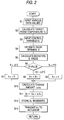
- Fig. 2 is a flowchart to show the air mix control operation of the auto amplifier 8.
- steps S1-S6 except step S3 are similar to the conventional process shown in Fig. 3 (steps S21-S26 except step S23); step S3 and step S7 and later steps are new steps.
- the auto amplifier 8 inputs various data values, such as a setup temperature from the temperature adjustment switch 15b, a cabin temperature from the inside air sensor 16, an outside temperature from the outside air sensor 17, the solar radiation amount from the solar radiation sensor 18, and a suction temperature from the suction temperature sensor 19, at step S1 and uses a preset vehicle thermal equilibrium constant to calculate a suction air target temperature in the cabin (target room temperature) Tm according to a predetermined calculation expression (for example, the same expression as used at step 522 in Fig. 3) at step S2.
- a predetermined calculation expression for example, the same expression as used at step 522 in Fig.
- the auto amplifier 8 inputs the control parameter (door opening target value) Xm stored in the memory 9 at step S3 and estimates air mix door opening X using a predetermined calculation expression (for example, the same expression as used at step S24 in Fig. 3) at step S4.
- a proper predetermined value for example, 0.5 (50%), etc., is entered in the memory 9 as an initial value of the control parameter Xm.
- the reason why the memory value is thus used to estimate (calculate) the door opening X is that the PBR value as in the conventional system is not input.
- the auto amplifier 8 uses the target room temperature Tm found at step S2 and the door opening X found at step S4 to calculate the deviation S value as an intermediate control parameter according to the following calculation expression at step S5:
- S Tm - (FX + G) (82 - Tint) - Tint where Tint is the suction temperature and F and G are constants. This expression is the same as that used at step S25 in Fig. 3.
- the auto amplifier 8 compares the S value with ⁇ 2°C at step S6. As the result of the comparison, if the S value is less than -2°C, the auto amplifier 8 decreases the value of the control parameter Xm a little; if the S value lies in the range of -2°C to +2°C, the auto amplifier 8 holds the Xm value intact; if the S value is greater than +2°C, the auto amplifier 8 increases the Xm value a little. Then, the auto amplifier 8 stores the Xm value in the memory 9 to update the contents of the memory 9.
- the change amount ⁇ Xm is determined according to a first-order lag at time constant ⁇ as one example.
- the corrected Xm value at step S11 is stored in the memory 9 at step S12, then is transmitted to the air mix door actuator 4a over the communication line 11 as control data for the air mix door actuator 4a at step S14.
- step S14 the auto amplifier 8 returns to step S1 and repeats execution of step S1 and the following steps in a predetermined short control cycle, whereby the actuator 4a performs positioning control of the air mix door 3 in response to the corrected command value (target opening) sent in sequence, namely, performs positioning control of the air mix door 3 while changing (correcting) the target opening of the air mix door 3 in the optimum direction in sequence, so that the air mix door 3 is always set to the optimum opening.
- the actuator 4a performs positioning control of the air mix door 3 in response to the corrected command value (target opening) sent in sequence, namely, performs positioning control of the air mix door 3 while changing (correcting) the target opening of the air mix door 3 in the optimum direction in sequence, so that the air mix door 3 is always set to the optimum opening.
- the control parameter transmitted to the actuator is calculated based on a predetermined intermediate control parameter.
- the intermediate control parameter is made the same as the control parameter in the conventional air mix control system, it can be calculated by the same method as the conventional method and the program change may be minimized. Therefore, the number of development steps is decreased and further the control program reliability is also maintained.
- this invention is applied to the air mix door and the contoller thereof.
- the embodiments of this invention is not limited to the aforementioned embodiment.
- this invention can be used to contoll the intake door, mode doors such as a deaf door, a vent door, and a foot door in the similar manner as described above.
Landscapes
- Physics & Mathematics (AREA)
- Thermal Sciences (AREA)
- Engineering & Computer Science (AREA)
- Mechanical Engineering (AREA)
- Air-Conditioning For Vehicles (AREA)
- Air Conditioning Control Device (AREA)
Abstract
Description
Claims (4)
- A door-opening controller for an automobile air conditioner comprising:a door to be opened at an arbitrary opening;an actuator for driving said door based on a given target position data; andcontrol means for controlling said actuator so as to always set said door to an optimum opening;wherein said control means calculates a predetermined intermediate control parameter from a target temperature in a cabin provided by performing operations on various input signals and an initial target position data stdred in an internal memory,corrects the initial target position data in sequence according to the intermediate control parameter value,stores the corrected target position data in said internal memory to update memory contents, andtransmits the target position data to said actuator by two-way serial communication.
- The door-opening controller for an automobile air conditioner according to claim 1, wherein said actuator inludes:a motor for driving said door;position detection means for outputting a current position of said door as a voltage; anda control circuit for controlling a rotation direction of said motor in response to the target position data and output of said position detection means.
- The door-opening controller for an automobile air conditioner according to claim 1, wherein the various input signals contain a set up temperature from temperture adjustment means provided in an antomobile, a cabin temperture, an outside temperture, solar radiation amount, and a suction temperture.
- A method for setting a door of an automobile air conditioner to an optimum opening, comprising the steps of:performing operations on various input signals so as to obtain a target temperature in a cabin;setting an initial target position data;calculating a predetermined intermediate control parameter based on the target temperture and the initial target position data;correcting the initial target position data in sequence according to the intermediate control parameter value;storing the corrected target position data; andtransmitting the target position data to an actuator for driving the door.
Applications Claiming Priority (3)
| Application Number | Priority Date | Filing Date | Title |
|---|---|---|---|
| JP19493396A JP3539825B2 (en) | 1996-07-24 | 1996-07-24 | Air mix control device for automotive air conditioner |
| JP194933/96 | 1996-07-24 | ||
| JP19493396 | 1996-07-24 |
Publications (3)
| Publication Number | Publication Date |
|---|---|
| EP0820886A2 true EP0820886A2 (en) | 1998-01-28 |
| EP0820886A3 EP0820886A3 (en) | 2000-03-08 |
| EP0820886B1 EP0820886B1 (en) | 2003-07-02 |
Family
ID=16332764
Family Applications (1)
| Application Number | Title | Priority Date | Filing Date |
|---|---|---|---|
| EP97112650A Expired - Lifetime EP0820886B1 (en) | 1996-07-24 | 1997-07-23 | Air mix controller of automobile air conditioner |
Country Status (5)
| Country | Link |
|---|---|
| US (1) | US5904293A (en) |
| EP (1) | EP0820886B1 (en) |
| JP (1) | JP3539825B2 (en) |
| KR (1) | KR100392118B1 (en) |
| DE (1) | DE69723162T2 (en) |
Cited By (4)
| Publication number | Priority date | Publication date | Assignee | Title |
|---|---|---|---|---|
| WO2001044632A3 (en) * | 1999-12-14 | 2001-12-27 | Bosch Gmbh Robert | Control valve |
| EP1362725A3 (en) * | 2002-05-15 | 2004-05-12 | Sanden Corporation | Control device |
| EP1479548A1 (en) * | 2003-05-22 | 2004-11-24 | Calsonic Kansei Corporation | Automobile servermotor controller |
| US8820372B2 (en) | 2008-12-05 | 2014-09-02 | Compagnie Generale Des Etablissements Michelin | Tire tread comprising incisions and recesses |
Families Citing this family (3)
| Publication number | Priority date | Publication date | Assignee | Title |
|---|---|---|---|---|
| US20030052180A1 (en) * | 2001-09-19 | 2003-03-20 | Trw Inc. | Method and apparatus for establishing addresses for plural actuators connected to a bus |
| KR100941807B1 (en) * | 2008-04-17 | 2010-02-10 | 현대자동차주식회사 | Control Apparatus for Automobile Actuator |
| US11458813B2 (en) | 2019-12-10 | 2022-10-04 | Valeo North America, Inc. | Heating, ventilation, and air conditioning (HVAC) assembly for managing air mixing door kinematics and method for managing the same |
Citations (5)
| Publication number | Priority date | Publication date | Assignee | Title |
|---|---|---|---|---|
| DE3222136A1 (en) * | 1981-06-11 | 1982-12-30 | Nippondenso Co., Ltd., Kariya, Aichi | DEVICE FOR CONTROLLING MOTOR VEHICLE AIR CONDITIONING |
| JPS61211110A (en) * | 1985-03-15 | 1986-09-19 | Diesel Kiki Co Ltd | On vehicle air conditioner |
| US4930698A (en) * | 1989-06-06 | 1990-06-05 | Diesel Kiki Co., Ltd. | Control apparatus for automobile air-conditioners |
| US4974776A (en) * | 1988-07-04 | 1990-12-04 | Diesel Kiki Co., Ltd. | Apparatus for controlling air-mix door in automobile air-conditioners |
| EP0709755A2 (en) * | 1994-10-27 | 1996-05-01 | General Motors Corporation | Automotive diagnostic communications |
Family Cites Families (4)
| Publication number | Priority date | Publication date | Assignee | Title |
|---|---|---|---|---|
| DE3128527A1 (en) * | 1981-07-18 | 1983-02-10 | Basf Ag, 6700 Ludwigshafen | NEW 3,4,5,6-TETRAHYDRO-1,2,4,6-THIATRIAZINE (3,5) -DION-1,1-DIOXIDE, METHOD FOR THE PRODUCTION THEREOF AND THEIR USE IN CONTROLLING UNWANTED PLANT GROWTH |
| JPS5939333A (en) * | 1982-08-31 | 1984-03-03 | Yoshikawa Kogyo Kk | Granulation of fine powdery coke in high efficiency |
| JP2573864B2 (en) * | 1988-05-20 | 1997-01-22 | 株式会社ゼクセル | Vehicle air conditioning controller |
| JP2519297B2 (en) * | 1988-05-20 | 1996-07-31 | 株式会社日立製作所 | Automotive air conditioner temperature controller |
-
1996
- 1996-07-24 JP JP19493396A patent/JP3539825B2/en not_active Expired - Fee Related
-
1997
- 1997-07-23 EP EP97112650A patent/EP0820886B1/en not_active Expired - Lifetime
- 1997-07-23 DE DE69723162T patent/DE69723162T2/en not_active Expired - Lifetime
- 1997-07-24 US US08/899,758 patent/US5904293A/en not_active Expired - Fee Related
- 1997-07-24 KR KR1019970034743A patent/KR100392118B1/en not_active IP Right Cessation
Patent Citations (5)
| Publication number | Priority date | Publication date | Assignee | Title |
|---|---|---|---|---|
| DE3222136A1 (en) * | 1981-06-11 | 1982-12-30 | Nippondenso Co., Ltd., Kariya, Aichi | DEVICE FOR CONTROLLING MOTOR VEHICLE AIR CONDITIONING |
| JPS61211110A (en) * | 1985-03-15 | 1986-09-19 | Diesel Kiki Co Ltd | On vehicle air conditioner |
| US4974776A (en) * | 1988-07-04 | 1990-12-04 | Diesel Kiki Co., Ltd. | Apparatus for controlling air-mix door in automobile air-conditioners |
| US4930698A (en) * | 1989-06-06 | 1990-06-05 | Diesel Kiki Co., Ltd. | Control apparatus for automobile air-conditioners |
| EP0709755A2 (en) * | 1994-10-27 | 1996-05-01 | General Motors Corporation | Automotive diagnostic communications |
Non-Patent Citations (1)
| Title |
|---|
| PATENT ABSTRACTS OF JAPAN vol. 011, no. 048 (M-561), 13 February 1987 (1987-02-13) & JP 61 211110 A (DIESEL KIKI CO LTD), 19 September 1986 (1986-09-19) * |
Cited By (6)
| Publication number | Priority date | Publication date | Assignee | Title |
|---|---|---|---|---|
| WO2001044632A3 (en) * | 1999-12-14 | 2001-12-27 | Bosch Gmbh Robert | Control valve |
| US6705586B2 (en) | 1999-12-14 | 2004-03-16 | Robert Bosch Gmbh | Control valve |
| EP1362725A3 (en) * | 2002-05-15 | 2004-05-12 | Sanden Corporation | Control device |
| EP1479548A1 (en) * | 2003-05-22 | 2004-11-24 | Calsonic Kansei Corporation | Automobile servermotor controller |
| US7061202B2 (en) | 2003-05-22 | 2006-06-13 | Calsonic Kansei Corporation | Automobile servomotor controller |
| US8820372B2 (en) | 2008-12-05 | 2014-09-02 | Compagnie Generale Des Etablissements Michelin | Tire tread comprising incisions and recesses |
Also Published As
| Publication number | Publication date |
|---|---|
| KR980008645A (en) | 1998-04-30 |
| EP0820886B1 (en) | 2003-07-02 |
| DE69723162T2 (en) | 2004-01-15 |
| JPH1035255A (en) | 1998-02-10 |
| DE69723162D1 (en) | 2003-08-07 |
| KR100392118B1 (en) | 2003-10-23 |
| US5904293A (en) | 1999-05-18 |
| EP0820886A3 (en) | 2000-03-08 |
| JP3539825B2 (en) | 2004-07-07 |
Similar Documents
| Publication | Publication Date | Title |
|---|---|---|
| US5832990A (en) | Automatic temperature control method and apparatus for an automotive vehicle | |
| US4325426A (en) | Air conditioner system | |
| JPS6021887B2 (en) | Vehicle air conditioning control device | |
| US5904293A (en) | Air mix controller of automobile air conditioner | |
| US6016964A (en) | Air-mix door control device for automobile air-conditioning system | |
| US4463801A (en) | Air induction control system for vehicle air conditioners | |
| US6745947B2 (en) | Vehicle air conditioner with automatic air-conditioning control | |
| JPS5934915A (en) | Controller for air-conditioning of automobile | |
| JPS6220456B2 (en) | ||
| US20210101446A1 (en) | Temperature adjustment device controller for convertible vehicle | |
| EP1466764A1 (en) | Method and device for controlling the air discharge temperature of an HVAC system | |
| JPH0872524A (en) | Vehicle air-conditioner | |
| JPS625804B2 (en) | ||
| JP3398512B2 (en) | Air mix control device for automotive air conditioner | |
| JP3029569B2 (en) | Vehicle air conditioning controller | |
| JP3212132B2 (en) | Vehicle air conditioner control method and control device | |
| JP3325428B2 (en) | Automotive air conditioners | |
| JPH0732853A (en) | Air conditioner for automobile | |
| JP3585304B2 (en) | Automotive air conditioning system | |
| JPH03178824A (en) | Air conditioning control device for vehicle | |
| JP3951965B2 (en) | Air conditioning control device and air conditioning device | |
| JP2965787B2 (en) | Air conditioning control method for automotive air conditioner | |
| JP3274172B2 (en) | Vehicle air conditioner control method and control device | |
| JPH0258125B2 (en) | ||
| JPS6213209B2 (en) |
Legal Events
| Date | Code | Title | Description |
|---|---|---|---|
| PUAI | Public reference made under article 153(3) epc to a published international application that has entered the european phase |
Free format text: ORIGINAL CODE: 0009012 |
|
| AK | Designated contracting states |
Kind code of ref document: A2 Designated state(s): DE FR GB |
|
| AX | Request for extension of the european patent |
Free format text: AL;LT;LV;RO;SI |
|
| RIN1 | Information on inventor provided before grant (corrected) |
Inventor name: OKASATO, YOSHITAKA |
|
| PUAL | Search report despatched |
Free format text: ORIGINAL CODE: 0009013 |
|
| AK | Designated contracting states |
Kind code of ref document: A3 Designated state(s): AT BE CH DE DK ES FI FR GB GR IE IT LI LU MC NL PT SE |
|
| AX | Request for extension of the european patent |
Free format text: AL;LT;LV;RO;SI |
|
| 17P | Request for examination filed |
Effective date: 20000426 |
|
| RAP1 | Party data changed (applicant data changed or rights of an application transferred) |
Owner name: CALSONIC KANSEI CORPORATION |
|
| AKX | Designation fees paid |
Free format text: DE FR GB |
|
| 17Q | First examination report despatched |
Effective date: 20020301 |
|
| GRAH | Despatch of communication of intention to grant a patent |
Free format text: ORIGINAL CODE: EPIDOS IGRA |
|
| GRAH | Despatch of communication of intention to grant a patent |
Free format text: ORIGINAL CODE: EPIDOS IGRA |
|
| GRAA | (expected) grant |
Free format text: ORIGINAL CODE: 0009210 |
|
| AK | Designated contracting states |
Designated state(s): DE FR GB |
|
| REG | Reference to a national code |
Ref country code: GB Ref legal event code: FG4D |
|
| RIN1 | Information on inventor provided before grant (corrected) |
Inventor name: OKASATO, YOSHITAKA |
|
| REF | Corresponds to: |
Ref document number: 69723162 Country of ref document: DE Date of ref document: 20030807 Kind code of ref document: P |
|
| ET | Fr: translation filed | ||
| PLBE | No opposition filed within time limit |
Free format text: ORIGINAL CODE: 0009261 |
|
| STAA | Information on the status of an ep patent application or granted ep patent |
Free format text: STATUS: NO OPPOSITION FILED WITHIN TIME LIMIT |
|
| 26N | No opposition filed |
Effective date: 20040405 |
|
| PGFP | Annual fee paid to national office [announced via postgrant information from national office to epo] |
Ref country code: FR Payment date: 20100805 Year of fee payment: 14 Ref country code: DE Payment date: 20100721 Year of fee payment: 14 |
|
| PGFP | Annual fee paid to national office [announced via postgrant information from national office to epo] |
Ref country code: GB Payment date: 20100721 Year of fee payment: 14 |
|
| GBPC | Gb: european patent ceased through non-payment of renewal fee |
Effective date: 20110723 |
|
| REG | Reference to a national code |
Ref country code: FR Ref legal event code: ST Effective date: 20120330 |
|
| PG25 | Lapsed in a contracting state [announced via postgrant information from national office to epo] |
Ref country code: DE Free format text: LAPSE BECAUSE OF NON-PAYMENT OF DUE FEES Effective date: 20120201 Ref country code: FR Free format text: LAPSE BECAUSE OF NON-PAYMENT OF DUE FEES Effective date: 20110801 |
|
| REG | Reference to a national code |
Ref country code: DE Ref legal event code: R119 Ref document number: 69723162 Country of ref document: DE Effective date: 20120201 |
|
| PG25 | Lapsed in a contracting state [announced via postgrant information from national office to epo] |
Ref country code: GB Free format text: LAPSE BECAUSE OF NON-PAYMENT OF DUE FEES Effective date: 20110723 |