EP0820831A1 - Method for forming wear resistant facings on ring groove areas of pistons of aluminium materials; piston for combustion engines - Google Patents
Method for forming wear resistant facings on ring groove areas of pistons of aluminium materials; piston for combustion engines Download PDFInfo
- Publication number
- EP0820831A1 EP0820831A1 EP97112844A EP97112844A EP0820831A1 EP 0820831 A1 EP0820831 A1 EP 0820831A1 EP 97112844 A EP97112844 A EP 97112844A EP 97112844 A EP97112844 A EP 97112844A EP 0820831 A1 EP0820831 A1 EP 0820831A1
- Authority
- EP
- European Patent Office
- Prior art keywords
- powder
- alloy
- silicon
- piston
- alloyed
- Prior art date
- Legal status (The legal status is an assumption and is not a legal conclusion. Google has not performed a legal analysis and makes no representation as to the accuracy of the status listed.)
- Granted
Links
Images

Classifications
-
- B—PERFORMING OPERATIONS; TRANSPORTING
- B23—MACHINE TOOLS; METAL-WORKING NOT OTHERWISE PROVIDED FOR
- B23K—SOLDERING OR UNSOLDERING; WELDING; CLADDING OR PLATING BY SOLDERING OR WELDING; CUTTING BY APPLYING HEAT LOCALLY, e.g. FLAME CUTTING; WORKING BY LASER BEAM
- B23K9/00—Arc welding or cutting
- B23K9/04—Welding for other purposes than joining, e.g. built-up welding
- B23K9/044—Built-up welding on three-dimensional surfaces
- B23K9/046—Built-up welding on three-dimensional surfaces on surfaces of revolution
-
- F—MECHANICAL ENGINEERING; LIGHTING; HEATING; WEAPONS; BLASTING
- F16—ENGINEERING ELEMENTS AND UNITS; GENERAL MEASURES FOR PRODUCING AND MAINTAINING EFFECTIVE FUNCTIONING OF MACHINES OR INSTALLATIONS; THERMAL INSULATION IN GENERAL
- F16J—PISTONS; CYLINDERS; SEALINGS
- F16J9/00—Piston-rings, e.g. non-metallic piston-rings, seats therefor; Ring sealings of similar construction
- F16J9/26—Piston-rings, e.g. non-metallic piston-rings, seats therefor; Ring sealings of similar construction characterised by the use of particular materials
-
- B—PERFORMING OPERATIONS; TRANSPORTING
- B23—MACHINE TOOLS; METAL-WORKING NOT OTHERWISE PROVIDED FOR
- B23K—SOLDERING OR UNSOLDERING; WELDING; CLADDING OR PLATING BY SOLDERING OR WELDING; CUTTING BY APPLYING HEAT LOCALLY, e.g. FLAME CUTTING; WORKING BY LASER BEAM
- B23K2103/00—Materials to be soldered, welded or cut
- B23K2103/08—Non-ferrous metals or alloys
- B23K2103/10—Aluminium or alloys thereof
Definitions
- the invention relates to a method for producing wear-resistant surfaces on ring groove areas of Piston made of aluminum-silicon alloy, being by Fusion alloying in the arc welding process Welding bead is applied.
- the invention relates furthermore a piston with an im Arc welding process melted Ring groove area.
- the present invention has for its object that Processes of the type described in the introduction improve that the disadvantages mentioned do not occur and the piston can withstand high loads.
- the process should also be economical be feasible.
- a piston should improved wear resistance of the melt-alloyed ring groove area can be created.
- This task is accomplished through a process of the beginning solved described type, which is characterized that when arc welding into the liquid weld pool or alloyed or unalloyed directly into the arc Copper powder, silicon powder or a mixture of copper and Silicon powder is introduced, as well as by a Piston according to claim 15.
- a fine-grained structure has a higher ductility as a coarse-grained, can therefore the proportion of nickel or Copper, i.e. the proportion of wear-resistant intermetallic phases in the structure can be increased without cracks appear in the weld bead after welding.
- the two-wire welding process is preferably used. It can be made of eutectic aluminum-silicon alloys existing wires that are available on the market, as well wires made of nickel and / or copper alloys can be used as electrodes.
- the amount of powder sprinkled in is advantageously such dimension that in the melt-alloyed ring groove area forms an aluminum-silicon alloy, the Silicon content 10, preferably 13 wt .-% or more is. Silicon then becomes primary or blocky eliminated, which increases wear resistance.
- additional alloying elements introduced with the powder or interspersed.
- additional alloying element For example, manganese can be added, or it can be a Grain refining agents, in particular titanium boron or zircon, be added.
- Such a quantity can also be used in reflow alloys Silicon powder are sprinkled in that the melt-alloyed ring groove area a hypereutectic Has structure.
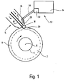
- Figure 1 shows a device in a schematic representation for reflow alloying of a pre-cast ring groove Piston 2 for an internal combustion engine.
- the device comprises a handling device 4 with which the machining piston 2 held in the horizontal direction and can be rotated about its piston axis 6.
- the Piston 2 preferably cooled from the inside.
- welding electrodes 10, 12 with a total of Reference numeral 14 designated arc welding device positionable.
- the electrode 10 can be made, for example an aluminum alloy, preferably AlSi12, and the Electrode 12 made of a nickel and / or copper alloy consist.
- the electrodes 10, 12 are of one Protective gas guide 16 surrounded with the in the area Arc 18 or in the area of the melt pool 20 Inert gas curtain is generated. There is only one for this slight flow velocity of the protective gas required. There is no undesirable turbulence or Vortex formation.
- feeder for a mixture of copper and Silicon powder provided one above the Piston jacket surface provided schematically shown Has reservoir 24, of which a pipe or channel-shaped feed section 26 leads away.
- Feed section 26 has one above the ends of the Electrodes 10, 12 and thus above the arc 18 or the melt pool 20 arranged mouth 28. Under Use of gravity causes the powder to slip or trickle from the reservoir 24 through the feed section 26 and is discharged through the mouth 28 and into the weld pool 20 interspersed.
- reference numeral 30 is one schematically indicated dosing device.
- the Scattered copper powder forms intermetallic phases (Copper aluminide) and it is primarily excreted silicon formed which the wear resistance of the melted ring groove area increased.
- Figure 2 shows a micrograph of the structure in one ring groove region melted according to the invention.
- Man recognizes silicon 32 that is excreted primarily and in blocks as well as the more or less rod-shaped intermetallic phases nickel and copper aluminide 34 and 36.
- silicon powder By adding silicon powder and by Alloying of the alloy containing nickel and / or copper through the second welding electrode the proportion of Alumiummatrix 38 reduced in the weld structure and thus the Wear resistance and hardness of the reflow alloy Ring groove area increased.
Abstract
Description
Die Erfindung betrifft ein Verfahren zur Herstellung von verschleißbeständigen Oberflächen an Ringnutbereichen von Kolben aus Aluminium-Silizium-Legierung, wobei durch Aufschmelzlegieren im Lichtbogenschweißverfahren eine Schweißraupe aufgetragen wird. Die Erfindung betrifft desweiteren einen Kolben mit einem im Lichtbogenschweißverfahren aufschmelzlegierten Ringnutbereich. The invention relates to a method for producing wear-resistant surfaces on ring groove areas of Piston made of aluminum-silicon alloy, being by Fusion alloying in the arc welding process Welding bead is applied. The invention relates furthermore a piston with an im Arc welding process melted Ring groove area.
Mit dem aus der DE 32 46 630 C2 und der DE 33 39 867 C2 und
auch aus der EP 0 095 604 B1 ansich bekannten
Aufschmelzlegieren von Ringnuten, vorzugsweise der ersten
Ringnut, soll eine Verstärkung des Ringnutbereichs erreicht
werden, ohne dass ein Eisen- oder Stahlringträger bei der
Herstellung des Kolbens eingegossen werden muss. Gemäß der
DE 33 39 867 C2 werden im sogenannten Zweidrahtverfahren am
Markt verfügbare (eutektische) Aluminium-Silizium-Drähte
und nickel- und/oder kupferhaltige Drähte als Elektroden
verwendet. Diese Elektroden werden im
Lichtbogenschweißverfahren aufgeschmolzen, und unter
Drehung des Kolbens um seine Kolbenachse wird die
vorgegossene Ringnut mit dem geschmolzenen
Elektrodenmaterial aufgefüllt. Dabei kommt es im
Schweißgefüge zu einer Verdünnung hinsichtlich Silizium.
Die für die Verschleißfestigkeit bedeutsamen primär
ausgeschiedenen Silizium-Kristalle werden nicht oder in
geringerem Maße gebildet. Daher waren bisher Kolben mit
einem aufschmelzlegierten Ringnutbereich für höhere
Beanspruchungen, wie sie Kolben für Dieselmotoren
ausgesetzt sind, nicht geeignet.With the from
Aus der CH 686 187 A5 ist ein Verfahren bekannt zum laserinduzierten Einschmelzen eines Pulvergemischs aus Siliziumcarbidpartikeln, Siliziumpulver und vorlegiertem AlSi-Pulver auf eine im Hinblick auf ihre Verschleißfestigkeit zu verbessernde Aluminiumsubstratoberfläche zur Bildung einer Metall-Matrix-Verbundschicht. Im Vordergrund stehen die Einbindung der keramischen Siliziumcarbidpartikel in die aufgeschmolzene Oberflächenschicht. Um eine Reaktion des SiC mit Aluminium zu Aluminiumcarbid (Al4C3) zu verhindern, wird Silizium, bevorzugt zu mehr als 20 Gew. %, zugesetzt. Zum Auffüllen einer Kolbenringnut wäre das Verfahren oder das Pulvergemisch nicht geeignet.From CH 686 187 A5, a method is known for laser-induced melting of a powder mixture of silicon carbide particles, silicon powder and pre-alloyed AlSi powder onto an aluminum substrate surface to be improved with regard to its wear resistance to form a metal-matrix composite layer. The focus is on the integration of the ceramic silicon carbide particles in the melted surface layer. In order to prevent a reaction of the SiC with aluminum to form aluminum carbide (Al 4 C 3 ), silicon, preferably more than 20% by weight, is added. The method or the powder mixture would not be suitable for filling a piston ring groove.
Der vorliegenden Erfindung liegt die Aufgabe zugrunde, das Verfahren der eingangs beschriebenen Art dahingehend zu verbessern, dass die genannten Nachteile nicht auftreten und der Kolben hohen Belastungen standzuhalten vermag. Das Verfahren soll desweiteren auf wirtschaftliche Weise durchführbar sein. Desweiteren soll ein Kolben mit verbesserter Verschleißbeständigkeit des aufschmelzlegierten Ringnutbereichs geschaffen werden.The present invention has for its object that Processes of the type described in the introduction improve that the disadvantages mentioned do not occur and the piston can withstand high loads. The The process should also be economical be feasible. Furthermore, a piston should improved wear resistance of the melt-alloyed ring groove area can be created.
Diese Aufgabe wird durch ein Verfahren der eingangs beschriebenen Art gelöst, das dadurch gekennzeichnet ist, dass beim Lichtbogenschweißen in das flüssige Schmelzbad oder direkt in den Lichtbogen legiertes oder unlegiertes Kupferpulver, Siliziumpulver oder eine Mischung aus Kupfer- und Siliziumpulver eingebracht wird, sowie durch einen Kolben nach Anspruch 15. This task is accomplished through a process of the beginning solved described type, which is characterized that when arc welding into the liquid weld pool or alloyed or unalloyed directly into the arc Copper powder, silicon powder or a mixture of copper and Silicon powder is introduced, as well as by a Piston according to claim 15.
Durch das Einstreuen des Kupferpulvers in das Schmelzbad oder den Lichtbogen wird der eutektische Punkt der aufzuschmelzenden Aluminium-Silizium-Legierung so verändert, dass Silizium auch bei verhältnismäßig geringen Silizium-Gehalten blockig, also primär ausgeschieden wird. Dies erweist sich im sogenannten Eindrahtverfahren als vorteilhaft, wenn mit einer einzigen eutektischen AlSi-Elekrode gearbeitet wird. - Wenn Siliziumpulver oder eine Mischung aus Kupfer- und Siliziumpulver eingebracht wird, so wird hierdurch das Schmelzgefüge des durch Abschmelzen des oder der Elektroden erhaltenen Füllmaterials derart mit Silizium "angereichert", dass sich verstärkt Siliziumkristalle primär ausscheiden. Durch das Einstreuen des Pulvers wird dem Schmelzbad auch Wärme entzogen, so dass eine rasche Abkühlung unter Ausbildung eines sehr feinkörnigen Gefüges erreicht wird.By sprinkling the copper powder into the weld pool or the arc becomes the eutectic point of the aluminum-silicon alloy to be melted so changed that silicon even at relatively low Silicon content is blocky, i.e. primarily excreted. This proves to be in the so-called single-wire process advantageous if with a single eutectic AlSi electrode is worked. - If silicon powder or one Mixture of copper and silicon powder is introduced, thus the melting structure becomes that of melting of the filling material or electrodes obtained in this way Silicon "enriched" that strengthens Eliminate silicon crystals primarily. By sprinkling heat is also removed from the molten bath, that rapid cooling to form a very fine-grained structure is achieved.
Beim Aufschmelzlegieren werden vorteilhafterweise Nickel und/oder Kupfer in Form der erschmolzenen Elektroden zulegiert, um die Härte und Verschleißbeständigkeit der Oberfläche des Ringnutbereichs durch die hierbei entstehenden intermetallischen Phasen zu erhöhen.When melting alloys are advantageously nickel and / or copper in the form of the fused electrodes alloyed to the hardness and wear resistance of the Surface of the annular groove area through the increasing intermetallic phases.
Da ein feinkörniges Gefüge eine höhere Duktilität aufweist als ein grobkörniges, kann daher der Anteil am Nickel oder Kupfer, d.h. der Anteil an verschleißbeständigen intermetallischen Phasen im Gefüge erhöht werden, ohne dass es nach dem Schweißen zu Rissen in der Schweißraupe kommt.Because a fine-grained structure has a higher ductility as a coarse-grained, can therefore the proportion of nickel or Copper, i.e. the proportion of wear-resistant intermetallic phases in the structure can be increased without cracks appear in the weld bead after welding.
Besonders vorteilhafte Ergebnisse wurden durch Einbringen von Pulver mit einer Körnung von 45 bis 75 µm erreicht.Particularly advantageous results have been brought in of powder with a grain size of 45 to 75 µm.
Bevorzugt findet das Zweidraht-Schweißverfahren Verwendung. Es können aus eutektischen Aluminium-Silizium-Legierungen bestehende Drähte, welche am Markt verfügbar sind, sowie aus Nickel- und/oder Kupfer-Legierungen bestehende Drähte als Elektroden verwendet werden.The two-wire welding process is preferably used. It can be made of eutectic aluminum-silicon alloys existing wires that are available on the market, as well wires made of nickel and / or copper alloys can be used as electrodes.
Die eingestreute Pulvermenge wird vorteilhafterweise derart
bemessen, dass sich im aufschmelzlegierten Ringnutbereich
eine Aluminium-Silizium-Legierung bildet, deren
Siliziumgehalt 10, vorzugsweise 13 Gew.-% oder mehr
beträgt. Silizium wird dann primär oder blockig
ausgeschieden, was die Verschleißfestigkeit erhöht.The amount of powder sprinkled in is advantageously such
dimension that in the melt-alloyed ring groove area
forms an aluminum-silicon alloy, the
In Weiterbildung der Erfindung werden zusätzliche Legierungselemente mit dem Pulver eingebracht bzw. eingestreut. Als zusätzliches Legierungselement kann beispielsweise Mangan zugegeben werden, oder es kann ein Kornfeinungsmittel, insbesondere Titanbor oder Zirkon, zugegeben werden. In a further development of the invention, additional Alloy elements introduced with the powder or interspersed. As an additional alloying element For example, manganese can be added, or it can be a Grain refining agents, in particular titanium boron or zircon, be added.
Desweiteren kann es vorteilhaft sein, wenn mit dem Pulver ein Material eingebracht wird, das mit dem Schmelzbad nur wenig oder gar nicht reagiert, wie zum Beispiel grobes Eisenpulver.Furthermore, it can be advantageous if with the powder a material is introduced that only with the weld pool little or no response, such as rough Iron powder.
Im aufschmelzlegierten Ringnutbereich weist ein erfindungsgemäß hergestellter Kolben primär oder blockig ausgeschiedenes Silizium auf.In the melt-alloyed annular groove area Piston produced according to the invention primary or blocky excreted silicon.
Wird ein Kolben aus der Aluminium-Silizium-Legierung AlSi12CuMg, also einer eutektischen Legierung hergestellt, so kommt es beim Aufschmelzlegieren notwendigerweise zu einer Verarmung der Siliziumphase, wenn im Zweidrahtverfahren zu der eutektischen Aluminium-Silizium-Elektrode noch eine zusätzliche Elektrode erschmolzen bzw. dazulegiert wird. Wird nach der Erfindung eine Mischung aus Kupfer- und Siliziumpulver eingestreut, so ist der Silizium-Gehalt gegenüber dem siliziumgehalt der Aluminium-Silizium-Legierung des Kolbenwerkstoffs im aufschmelzlegierten Bereich nicht verringert; auch in diesem Bereich liegt primär oder blockig ausgeschiedenes Silizium vor.Becomes a piston made of aluminum-silicon alloy AlSi12CuMg, i.e. a eutectic alloy, this is necessarily the case with reflow alloying depletion of the silicon phase if in Two-wire process for the eutectic aluminum-silicon electrode another electrode melted or is added. According to the invention, a mixture of Scattered copper and silicon powder, that's how it is Silicon content compared to the silicon content of the aluminum-silicon alloy of the piston material in melting area not reduced; also in this area is primarily or blockily excreted Silicon before.
Beim Aufschmelzlegieren kann auch eine solche Menge Siliziumpulver eingestreut werden, dass der aufschmelzlegierte Ringnutbereich ein übereutektisches Gefüge aufweist.Such a quantity can also be used in reflow alloys Silicon powder are sprinkled in that the melt-alloyed ring groove area a hypereutectic Has structure.
Es wird ausdrücklich darauf hingewiesen, dass vorteilhafte Ergebnisse im besonderen bei der Anwendung des Zweidrahtverfahrens auch erzielt werden, wenn kein Kupferpulver sondern nur Siliziumpulver in das Schmelzbad oder den Lichtbogen eingebracht wird.It is expressly pointed out that advantageous Results in particular when using the Two-wire process can also be achieved if none Copper powder but only silicon powder in the weld pool or the arc is introduced.
Weitere Merkmale, Einzelheiten und Vorteile der Erfindung ergeben sich aus den Schutzansprüchen und der beigefügten Zeichnung und nachfolgenden Beschreibung der Erfindung. In der Zeichnung zeigt:
- Figur 1
- eine schematische Darstellung einer erfindungsgemäßen Vorrichtung zum Aufschmelzlegieren einer vorgegossenen Ringnut;
Figur 2- ein Schliffbild des Gefüges in einem aufschmelzlegierten Ringnutbereichs eines Kolbens.
- Figure 1
- a schematic representation of a device according to the invention for reflow alloying of a pre-cast annular groove;
- Figure 2
- a micrograph of the structure in a melt-alloyed annular groove area of a piston.
Figur 1 zeigt in schematischer Darstellung eine Vorrichtung
zum Aufschmelzlegieren einer vorgegossenen Ringnut eines
Kolbens 2 für eine Brennkraftmaschine. Die Vorrichtung
umfasst eine Handhabungseinrichtung 4, mit der der zu
bearbeitende Kolben 2 in horizontaler Richtung gehalten und
um seine Kolbenachse 6 gedreht werden kann. Dabei wird der
Kolben 2 vorzugsweise von innen gekühlt. Unmittelbar
oberhalb des Kolbens 2 im Bereich der vorgegossenen Ringnut
8 sind Schweißelektroden 10, 12 einer insgesamt mit dem
Bezugszeichen 14 bezeichneten Lichtbogenschweißeinrichtung
positionierbar. Die Elektrode 10 kann beispielsweise aus
einer Aluminiumlegierung, vorzugsweise AlSi12, und die
Elektrode 12 aus einer Nickel- und/oder Kupferlegierung
bestehen. Die Elektroden 10, 12 sind von einer
Schutzgasführung 16 umgeben, mit der im Bereich des
Lichtbogens 18 bzw. im Bereich des Schmelzbads 20 ein
Schutzgasschleier erzeugt wird. Hierfür ist nur eine sehr
geringfügige Strömungsgeschwindigkeit des Schutzgases
erforderlich. Es kommt zu keinen unerwünschten Turbulenz- oder
Wirbelbildungen.Figure 1 shows a device in a schematic representation
for reflow alloying of a pre-cast ring groove
Piston 2 for an internal combustion engine. The device
comprises a handling device 4 with which the
Es ist desweiteren eine mit dem Bezugszeichen 22
bezeichnete Zuführeinrichtung für eine Mischung aus Kupfer- und
Siliziumpulver vorgesehen, die einen oberhalb der
Kolbenmantelfläche vorgesehenen schematisch dargestellten
Vorratsbehälter 24 aufweist, von dem ein rohr- oder
rinnenförmiger Zuführabschnitt 26 wegführt. Der
Zuführabschnitt 26 weist eine oberhalb der Enden der
Elektroden 10, 12 und damit oberhalb des Lichtbogens 18
bzw. des Schmelzbads 20 angeordnete Mündung 28 auf. Unter
Ausnützung der Schwerkraft rutscht oder rieselt das Pulver
aus dem Vorratsbehälter 24 durch den Zuführabschnitt 26 und
wird durch die Mündung 28 abgegeben und in das Schmelzbad
20 eingestreut. Mit dem Bezugszeichen 30 ist eine
schematisch angedeutete Dosiervorrichtung bezeichnet.It is also one with the
Durch die Zugabe des Pulvers in das Schmelzbad 20 wird eine Erhöhung des Siliziumgehalts erreicht und der eutektische Punkt wird so verschoben, dass sich auch bei geringeren SiKonzentrationen primäre Silizium-Ausscheidungen bilden. Das eingestreute Kupferpulver bildet intermetallische Phasen (Kupferaluminid) und es wird primär ausgeschiedenes Silizum gebildet, welches die Verschleißfestigkeit des aufschmelzlegierten Ringnutbereichs erhöht.By adding the powder to the molten bath 20 a Increased silicon content and the eutectic The point is shifted so that even at lower Si concentrations form primary silicon precipitates. The Scattered copper powder forms intermetallic phases (Copper aluminide) and it is primarily excreted silicon formed which the wear resistance of the melted ring groove area increased.
Durch die Zugabe von Kupfer- und Siliziumpulver sowie durch das Zulegieren der nickel- und/oder kupferhaltigen Legierung durch die zweite Schweißelektrode wird der Anteil der Aluminiummatrix im Schweißgefüge reduziert und damit die Verschleißfestigkeit und Härte des aufschmelzlegierten Ringnutbereichs erhöht.By adding copper and silicon powder and by alloying of those containing nickel and / or copper Alloy through the second welding electrode becomes the part the aluminum matrix in the welded structure and thus reduced the wear resistance and hardness of the reflow alloy Ring groove area increased.
Figur 2 zeigt ein Schliffbild des Gefüges in einem
erfindungsgemäß aufschmelzlegierten Ringnutbereich. Man
erkennt primär und blockig ausgeschiedenes Silizium 32
sowie die mehr oder weniger stabförmig ausgeschiedenen
intermetallischen Phasen Nickel- und Kupferaluminid 34 bzw.
36. Durch die Zugabe von Siliziumpulver sowie durch das
Zulegierung der nickel- und/oder kupferhaltigen Legierung
durch die zweite Schweißelektrode wird der Anteil der
Alumiummatrix 38 im Schweißgefüge reduziert und damit die
Verschleißfestigkeit und Härte des aufschmelzlegierten
Ringnutbereichs erhöht.Figure 2 shows a micrograph of the structure in one
ring groove region melted according to the invention. Man
recognizes
Claims (15)
Applications Claiming Priority (2)
| Application Number | Priority Date | Filing Date | Title |
|---|---|---|---|
| DE19630197 | 1996-07-26 | ||
| DE19630197A DE19630197C2 (en) | 1996-07-26 | 1996-07-26 | Process for producing wear-resistant surfaces on components made of aluminum materials and device for carrying it out; Pistons for internal combustion engines |
Publications (2)
| Publication Number | Publication Date |
|---|---|
| EP0820831A1 true EP0820831A1 (en) | 1998-01-28 |
| EP0820831B1 EP0820831B1 (en) | 1999-04-14 |
Family
ID=7800925
Family Applications (1)
| Application Number | Title | Priority Date | Filing Date |
|---|---|---|---|
| EP97112844A Expired - Lifetime EP0820831B1 (en) | 1996-07-26 | 1997-07-25 | Method for forming wear resistant facings on ring groove areas of pistons of aluminium materials; piston for combustion engines |
Country Status (2)
| Country | Link |
|---|---|
| EP (1) | EP0820831B1 (en) |
| DE (2) | DE19630197C2 (en) |
Cited By (3)
| Publication number | Priority date | Publication date | Assignee | Title |
|---|---|---|---|---|
| EP1190810A1 (en) * | 2000-09-13 | 2002-03-27 | Federal-Mogul Nürnberg GmbH | Method of manufacturing a piston |
| EP1386687A1 (en) * | 2002-07-30 | 2004-02-04 | Federal-Mogul Nürnberg GmbH | Process for making a piston and piston |
| WO2009043537A1 (en) * | 2007-09-26 | 2009-04-09 | Ks Kolbenschmidt Gmbh | Reinforcement of an annular groove of a piston for an internal combustion engine |
Families Citing this family (4)
| Publication number | Priority date | Publication date | Assignee | Title |
|---|---|---|---|---|
| DE19907105A1 (en) | 1999-02-19 | 2000-08-31 | Volkswagen Ag | Method and device for producing wear-resistant, tribological cylinder running surfaces |
| DE19915038A1 (en) | 1999-04-01 | 2000-10-26 | Vaw Ver Aluminium Werke Ag | Light metal cylinder block, method for its production and device for carrying out the method |
| AT4665U1 (en) | 2000-07-14 | 2001-10-25 | Plansee Tizit Ag | METHOD FOR PRESSING A CUTTING INSERT |
| DE10202193B4 (en) * | 2002-01-22 | 2006-11-23 | Man B&W Diesel A/S | Method for providing a large machine component with a protective coating |
Citations (3)
| Publication number | Priority date | Publication date | Assignee | Title |
|---|---|---|---|---|
| DE3246630A1 (en) * | 1982-12-16 | 1984-06-20 | Karl Schmidt Gmbh, 7107 Neckarsulm | Method of producing wear-resistant surfaces on the ring grooves of aluminium-alloy pistons for internal combustion engines |
| DE3339867A1 (en) * | 1982-12-16 | 1985-05-15 | Kolbenschmidt AG, 7107 Neckarsulm | METHOD FOR THE PRODUCTION OF WEAR-RESISTANT SURFACES OF THE RING GROOVES OF PISTONS, MADE OF ALUMINUM ALLOYS, FOR INTERNAL COMBUSTION ENGINES |
| JPH02169182A (en) * | 1988-12-21 | 1990-06-29 | Atsugi Unisia Corp | Wear resistant alloy member and its manufacture and filler metal used for same manufacture |
Family Cites Families (5)
| Publication number | Priority date | Publication date | Assignee | Title |
|---|---|---|---|---|
| DE2200003B2 (en) * | 1972-01-03 | 1977-09-15 | Karl Schmidt Gmbh, 7107 Neckarsulm | PROCESS FOR SURFACE FINISHING OF LIGHT ALLOY PISTONS |
| US4432313A (en) * | 1982-05-27 | 1984-02-21 | Trw Inc. | Aluminum base material with hard facing deposit |
| DE3922378A1 (en) * | 1989-07-07 | 1991-01-17 | Audi Ag | METHOD FOR PRODUCING WEAR-RESISTANT SURFACES ON COMPONENTS FROM AN ALUMINUM-SILICUM ALLOY |
| JPH04100693A (en) * | 1990-08-21 | 1992-04-02 | Showa Alum Corp | Filler metal for surface reforming of aluminum material |
| CH686187A5 (en) * | 1993-03-30 | 1996-01-31 | Alusuisse Lonza Services Ag | Metal substrates with laser-induced MMC coating. |
-
1996
- 1996-07-26 DE DE19630197A patent/DE19630197C2/en not_active Expired - Lifetime
-
1997
- 1997-07-25 EP EP97112844A patent/EP0820831B1/en not_active Expired - Lifetime
- 1997-07-25 DE DE59700130T patent/DE59700130D1/en not_active Expired - Lifetime
Patent Citations (3)
| Publication number | Priority date | Publication date | Assignee | Title |
|---|---|---|---|---|
| DE3246630A1 (en) * | 1982-12-16 | 1984-06-20 | Karl Schmidt Gmbh, 7107 Neckarsulm | Method of producing wear-resistant surfaces on the ring grooves of aluminium-alloy pistons for internal combustion engines |
| DE3339867A1 (en) * | 1982-12-16 | 1985-05-15 | Kolbenschmidt AG, 7107 Neckarsulm | METHOD FOR THE PRODUCTION OF WEAR-RESISTANT SURFACES OF THE RING GROOVES OF PISTONS, MADE OF ALUMINUM ALLOYS, FOR INTERNAL COMBUSTION ENGINES |
| JPH02169182A (en) * | 1988-12-21 | 1990-06-29 | Atsugi Unisia Corp | Wear resistant alloy member and its manufacture and filler metal used for same manufacture |
Non-Patent Citations (1)
| Title |
|---|
| PATENT ABSTRACTS OF JAPAN vol. 014, no. 428 (M - 1025) 14 September 1990 (1990-09-14) * |
Cited By (4)
| Publication number | Priority date | Publication date | Assignee | Title |
|---|---|---|---|---|
| EP1190810A1 (en) * | 2000-09-13 | 2002-03-27 | Federal-Mogul Nürnberg GmbH | Method of manufacturing a piston |
| US6546626B2 (en) | 2000-09-13 | 2003-04-15 | Federal-Mogul Nürnberg GmbH | Method of producing a piston |
| EP1386687A1 (en) * | 2002-07-30 | 2004-02-04 | Federal-Mogul Nürnberg GmbH | Process for making a piston and piston |
| WO2009043537A1 (en) * | 2007-09-26 | 2009-04-09 | Ks Kolbenschmidt Gmbh | Reinforcement of an annular groove of a piston for an internal combustion engine |
Also Published As
| Publication number | Publication date |
|---|---|
| DE19630197A1 (en) | 1998-01-29 |
| DE59700130D1 (en) | 1999-05-20 |
| EP0820831B1 (en) | 1999-04-14 |
| DE19630197C2 (en) | 1999-10-14 |
Similar Documents
| Publication | Publication Date | Title |
|---|---|---|
| EP0973953B1 (en) | Device for precipitating compounds from zinc metal baths by means of a hollow rotary body that can be driven about an axis and is dipped into the molten zinc | |
| DE3506302C2 (en) | ||
| EP1124660B1 (en) | A cylinder crank case, method for the manufacture of a cylinder liner therefor and method for the production of the cylinder crank case with said cylinder liners | |
| DE3339867A1 (en) | METHOD FOR THE PRODUCTION OF WEAR-RESISTANT SURFACES OF THE RING GROOVES OF PISTONS, MADE OF ALUMINUM ALLOYS, FOR INTERNAL COMBUSTION ENGINES | |
| DE3305633C2 (en) | ||
| DE3344450C2 (en) | ||
| EP0871791B1 (en) | Process for manufacturing cylinder liners | |
| DE2200003A1 (en) | PROCESS FOR SURFACE FINISHING OF LIGHT METAL COMPONENTS | |
| DE60003221T2 (en) | CAST IRON ALLOY | |
| EP0820831B1 (en) | Method for forming wear resistant facings on ring groove areas of pistons of aluminium materials; piston for combustion engines | |
| EP1157141B1 (en) | Method and device for treating a component surface | |
| DE102010055055B3 (en) | Use of a copper-tin multi-substance bronze | |
| DE4201793C2 (en) | Bearing metal for large-sized engines | |
| DE3114124A1 (en) | ALUMINUM PISTON WITH HARDOXIZED BOTTOM | |
| DE4142454C2 (en) | Composite sliding element and method for its production | |
| DE3246630C2 (en) | ||
| DE2830459B2 (en) | Use of a brass alloy for parts with high resistance to corrosive wear | |
| DE10124250C2 (en) | Method of forming a high strength and wear resistant composite layer | |
| DE19800433C2 (en) | Continuous casting process for casting an aluminum plain bearing alloy | |
| DE4408717A1 (en) | Composite element for coating the tip of screw feeder blades | |
| DE2213230B2 (en) | Cored wire electrode for electroslag welding | |
| EP0042455B1 (en) | Aluminium- and cobalt-containing copper alloys with high wear resistance; process for the manufacture of these alloys | |
| DE3114701C2 (en) | Process for surfacing a metal layer on an aluminum alloy | |
| DE2510630C3 (en) | Electrode tape with powder filling for build-up welding of wear-resistant composite alloys | |
| EP0141966A1 (en) | Process for centrifugal casting |
Legal Events
| Date | Code | Title | Description |
|---|---|---|---|
| PUAI | Public reference made under article 153(3) epc to a published international application that has entered the european phase |
Free format text: ORIGINAL CODE: 0009012 |
|
| AK | Designated contracting states |
Kind code of ref document: A1 Designated state(s): AT BE CH DE DK ES FI FR GB GR IE IT LI LU MC NL PT SE |
|
| AX | Request for extension of the european patent |
Free format text: AL;LT;LV;RO;SI |
|
| 17P | Request for examination filed |
Effective date: 19980127 |
|
| 17Q | First examination report despatched |
Effective date: 19980319 |
|
| GRAG | Despatch of communication of intention to grant |
Free format text: ORIGINAL CODE: EPIDOS AGRA |
|
| RBV | Designated contracting states (corrected) |
Designated state(s): DE ES FR GB |
|
| GRAG | Despatch of communication of intention to grant |
Free format text: ORIGINAL CODE: EPIDOS AGRA |
|
| GRAH | Despatch of communication of intention to grant a patent |
Free format text: ORIGINAL CODE: EPIDOS IGRA |
|
| GRAH | Despatch of communication of intention to grant a patent |
Free format text: ORIGINAL CODE: EPIDOS IGRA |
|
| GRAA | (expected) grant |
Free format text: ORIGINAL CODE: 0009210 |
|
| AK | Designated contracting states |
Kind code of ref document: B1 Designated state(s): DE ES FR GB |
|
| PG25 | Lapsed in a contracting state [announced via postgrant information from national office to epo] |
Ref country code: GB Free format text: LAPSE BECAUSE OF NON-PAYMENT OF DUE FEES Effective date: 19990414 Ref country code: FR Free format text: LAPSE BECAUSE OF FAILURE TO SUBMIT A TRANSLATION OF THE DESCRIPTION OR TO PAY THE FEE WITHIN THE PRESCRIBED TIME-LIMIT Effective date: 19990414 Ref country code: ES Free format text: THE PATENT HAS BEEN ANNULLED BY A DECISION OF A NATIONAL AUTHORITY Effective date: 19990414 |
|
| REF | Corresponds to: |
Ref document number: 59700130 Country of ref document: DE Date of ref document: 19990520 |
|
| PGFP | Annual fee paid to national office [announced via postgrant information from national office to epo] |
Ref country code: DE Payment date: 19990827 Year of fee payment: 3 |
|
| EN | Fr: translation not filed | ||
| GBV | Gb: ep patent (uk) treated as always having been void in accordance with gb section 77(7)/1977 [no translation filed] |
Effective date: 19990414 |
|
| PLBQ | Unpublished change to opponent data |
Free format text: ORIGINAL CODE: EPIDOS OPPO |
|
| PLBI | Opposition filed |
Free format text: ORIGINAL CODE: 0009260 |
|
| PLAV | Examination of admissibility of opposition |
Free format text: ORIGINAL CODE: EPIDOS OPEX |
|
| PLAV | Examination of admissibility of opposition |
Free format text: ORIGINAL CODE: EPIDOS OPEX |
|
| PLBF | Reply of patent proprietor to notice(s) of opposition |
Free format text: ORIGINAL CODE: EPIDOS OBSO |
|
| 26 | Opposition filed |
Opponent name: FEDERAL MOGUL NUERNBERG GMBH Effective date: 20000114 Opponent name: MAHLE GMBH Effective date: 20000104 |
|
| PLBF | Reply of patent proprietor to notice(s) of opposition |
Free format text: ORIGINAL CODE: EPIDOS OBSO |
|
| PG25 | Lapsed in a contracting state [announced via postgrant information from national office to epo] |
Ref country code: DE Free format text: LAPSE BECAUSE OF THE APPLICANT RENOUNCES Effective date: 20000711 |
|
| PLBL | Opposition procedure terminated |
Free format text: ORIGINAL CODE: EPIDOS OPPC |
|
| PLBM | Termination of opposition procedure: date of legal effect published |
Free format text: ORIGINAL CODE: 0009276 |
|
| STAA | Information on the status of an ep patent application or granted ep patent |
Free format text: STATUS: OPPOSITION PROCEDURE CLOSED |
|
| 27C | Opposition proceedings terminated |
Effective date: 20020901 |