EP0820697B2 - Skin-holding vent cutter - Google Patents
Skin-holding vent cutter Download PDFInfo
- Publication number
- EP0820697B2 EP0820697B2 EP97202354A EP97202354A EP0820697B2 EP 0820697 B2 EP0820697 B2 EP 0820697B2 EP 97202354 A EP97202354 A EP 97202354A EP 97202354 A EP97202354 A EP 97202354A EP 0820697 B2 EP0820697 B2 EP 0820697B2
- Authority
- EP
- European Patent Office
- Prior art keywords
- skin
- vent
- pin
- holding element
- animal
- Prior art date
- Legal status (The legal status is an assumption and is not a legal conclusion. Google has not performed a legal analysis and makes no representation as to the accuracy of the status listed.)
- Expired - Lifetime
Links
Images

Classifications
-
- A—HUMAN NECESSITIES
- A22—BUTCHERING; MEAT TREATMENT; PROCESSING POULTRY OR FISH
- A22B—SLAUGHTERING
- A22B5/00—Accessories for use during or after slaughtering
- A22B5/0094—Cutting or blocking the rectum of a carcass, e.g. for avoiding fecal contamination
-
- A—HUMAN NECESSITIES
- A22—BUTCHERING; MEAT TREATMENT; PROCESSING POULTRY OR FISH
- A22C—PROCESSING MEAT, POULTRY, OR FISH
- A22C21/00—Processing poultry
- A22C21/06—Eviscerating devices for poultry
Definitions
- This invention is a device for cutting out the vent, which is the excretory canal of a slaughtered animal, such as poultry, pigs, other mammals or the like, in order to cut the vent completely out.
- the device uses a holding element to capture the skin surrounding the vent.
- a cutter cooperates with the holding element in order to cut through the typically highly-elastic skin with a shearing action.
- Vents of slaughtered animals such as poultry, pigs or the like must be cut out and removed during processing, typically as a prelude to eviscerating the animal.
- regulations require complete removal of the vent, including the orbicular muscle surrounding the vent exit.
- Devices also exist for clamping or positioning the orbicular muscle before cutting.
- U.S. Patent No. 5,133,686 fixes the orbicular muscle in place before cutting by using an annular gap carefully-sized to capture the orbicular muscle. Pulling the clamped orbicular muscle away from the carcass draws the intestines at least partially out.
- vent cutters are often placed on a rotary processor that operates on poultry or other carcasses suspended from an adjacent overhead conveyor and clamped to the processor during vent removal. Some machines leave a piece of orbicular muscle on a small number of carcasses. Possibly, this failure completely to cut out the orbicular muscle is caused by the movement of the rotary apparatus (the uncut orbicular muscle often occurs on the edge of the carcass trailing the direction of rotary movement) or the high elasticity of the animal skin that must be cut. In any event, left-over bits of orbicular muscle hurt the quality scores for the processing plants and may ultimately reduce the quality of the product.
- This invention overcomes the above problems by providing a holding element that holds the skin of the animal surrounding the vent exit.
- the holding element thereby prevents the skin from twisting when cut by the rotary cutter.
- the face surface of the holding element may be beveled to provide more surface area for contacting the skin. The increased surface area can better withstand the initiation of the cutting action. That cutting action begins first only at the "high" point of the bevel, which causes the cutting action to build up more smoothly, improving the cut.
- the face surface is roughened in order to capture and hold the skin, preventing it from the typical twisting that makes cutting more difficult.
- a series of grooves may be formed in the face surface. Such grooves capture and hold the skin. The grooves also form the skin into folds that are easier to cut through than the unfolded, elastic skin of the typical animal carcass.
- the holding element cooperates with the rotary cutter to cut through the skin with a shearing action that makes a cleaner, better cut.
- the cutter and holding element are positioned fairly close to one another, separated only by a small annular gap whose width ranges from about 0.1 to 1 millimeters (mm).
- An elongated centering pin terminating in a knob may be coaxial to and nested within the holding element, which, in turn, is coaxial to and nested within a rotary cutter.
- the rotary cutter may be generally cylindrical in shape.
- Each of these elements can move toward and away from a slaughtered animal, which is typically suspended from an overhead conveyor adjacent to a rotary processing machine holding numerous assemblies containing the pin, holding element and cutter. Clamping devices on the processor fix the poultry carcasses in position for cutting.
- blocks connected to each of the various assemblies slide within corresponding tracks in the processor.
- the slide blocks move the various elements of each assembly.
- the tracks and blocks can be arranged so that as the processor rotates, tracks move a sliding block down, which moves the centering pin into the vent of a poultry carcass held in an overhead conveyor and clamped to the side of the processor underneath the pin.
- the holding element is similarly moved toward the carcass.
- the terminating knob on the pin passes through the orbicular muscle into the vent.
- the resilient orbicular muscle closes around the pin shaft that has a smaller diameter than the knob on its terminating end. Meanwhile, the holding element has been brought to abut against the skin of the animal surrounding the vent.
- the face surface or the holding element may be appropriately beveled to improve contact with the carcass.
- slide blocks move the pin toward the holding element, which has a recess that cooperates with the shoulder of the knob to clasp the orbicular muscle. Moving the pin and holding element slightly further away from the carcass lifts the clamped orbicular muscle.
- the pin and holding element clasp the orbicular muscle between them. Also, the skin is held by the roughened face surface of the holding element. Because the cutter and holding element are fairly close to one another, a shearing force is created that improves cutting of the skin. Cutting may be further improved by using grooves to roughen the face surface. The grooves form folds in the skin, allowing the rotary cutter initially to focus its cutting forces on the tops of the folds.
- the pin and holding element After cutting, the pin and holding element are retracted from the carcass to pull away the orbicular muscle and an attached section of intestine. Separating the pin and holding element then releases the completely cut free orbicular muscle.
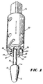
- Figure 1 shows a perspective view of the vent cutter of the present invention.
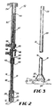
- Figure 2 shows a side, cross-sectional view of the vent cutter and assembly of the present invention.
- Figure 3 shows a side view of the holding element used in the vent cutter of the present invention.
- Figure 4 shows a front view of the vent cutter of the present invention.
- Figure 5 shows a schematic view of the vent cutter of the present invention in use.
- FIG 1 shows a perspective view of the vent cutter of the present invention.
- a centering pin 10 terminates in a generally cone-shaped probe 12 forming a shoulder 14 that leads to an elongated shaft 16.
- the centering pin 10 is coaxial to a holding element 20, shown as a partial, hollowed cylinder.
- Pin shaft 16 extends from and retracts into the holding element 20 so that the shoulder 14 of the probe 12 is drawn into a recess 26 formed in the holding element 20, as shown in Figure 2 .
- Both the pin 10 and holding element 20 may be nested within and coaxial to a rotary cutter 30 in order to form an assembly 40.
- a small annular space separates the outside of the holding element 20 from the inside of the cutter 30.
- the annular space between the holding element 20 and cutter 30 shown in the Figure 1 embodiment is about 0.25 millimeters ("mm") wide (This 0.25 mm width is the difference between the outer and inner diameters defining the annular space).
- the annular space may range between about 0.1 and 1 mm. Even more or less separation can be used so long as the cutter 30 can cooperate with the holding element 20 to shear through the skin.
- Pin 10 has a solid shaft 16 passing through a bore 28 in the holding element 20.
- the terminating end of the holding element 20 forms the recess 26 into which the shoulders 14 ofthe cone-shaped probe 12 seat.
- Pin shaft 16 extends through a hollow shaft 21 that, in turn, extends through a square shaft 42.
- Square shaft 42 rotates in order to spin blades 32 on the rotary cutter 30, which attaches to the square shaft 42 via a retainer 34. Since the square shaft 42 rotates, it connects to a fixed shaft 50 through a bushing 43 and washer 44 arrangement.
- Pin shaft 16 and hollow shaft 21 may extend and retract within the square shaft 42; but neither the pin shaft 16 nor the hollow shaft 21 rotates.
- Moving a first slide block 45 within a track or slot also moves the pin 10 and holding element 20.
- a bolt 46 secures first slide block 45 to the pin shaft 16.
- shoulder 14 engages recess 26, thereby also moving holding element 20.
- a spring 47 biases the hollow shaft 21 toward blades 32 on the cutter 30. The initial bias of the spring 47 may be adjusted by relocating into any of a number of spaced holes a set screw 48 against which one end of spring 47 bears. Another set screw 49 holds holding element 20 inside shaft 50 by protruding into slot 29.
- Moving a second block 52 within a slot or track extends and retracts moving the entire assembly 40 toward and away from an animal carcass held in, for instance, the clamps shown in Figure 4 .
- Those clamps are operated by sliding a third block 54 within a track
- gears shown in Figure 4
- slide blocks While the holding element 20 is in an end position adjacent to the carcass in order to hold the skin, slide blocks will extend the blade 32 toward the carcass held in the clamps, thereby initiating cutting and vent removal.
- Figure 3 shows additional detail about the holding element 20.
- a face surface 22 is formed at the terminating end of holding element 20.
- the face surface 22 is beveled at an angle 23 selected to maximize contact of the face surface 22 with the skin of a carcass, which typically is tilted by clamps on a processing station.
- angle 23 shown in Figure 3 is at a 10° angle to a line perpendicular to the axis of hollow shaft 21.
- Face surface 22 is roughened so as to better capture and hold the skin of a carcass.
- One way to roughen the surface is to form various grooves 24 in the face surface 22 so that teeth 25 can capture and hold the skin surrounding the animal's vent.
- face surface 22 may be provided with serrated edges, small ridges or strips of abrasive material such as sandpaper or the like.
- grooves 24 and teeth 25 with the spring 47 results in the spring 47 forcing the holding element 20 toward the animal, which forces skin into grooves 24 to form the skin into folds.
- Grooves 24 at the back 27 of the holding element 20 need not be as deep or sharply defined as grooves 24 at the front.
- the assembly 40 may be mounted in a rotary processor provided with various tracks for moving slide blocks 45, 52 and 54 in order to extend and retract elements of the assembly 40.
- the pin 10 or holding element 20 may also be extended and retracted by using hydraulics or solenoids.
- the rotary processor may have gears or other mechanisms for rotating the square shaft 42.
- Figure 5 shows a schematic view of an assembly 40 in operation.
- Probe 12 at the terminating end of pin 10 is located underneath skin 60 of a carcass.
- the elastic orbicular muscle at the end of the vent stretched around the probe 12 and then contracted around the narrower shaft 16. While this occurred, the cutter 30 and holding element 20 dropped toward the carcass.
- the holding element 20 first reached the carcass and holds the skin in grooves 24. Cutting was started and the probe 12 was then retracted toward the holding element 20 in order to clasp the orbicular muscle between the shoulders 14 of the probe 12 and the recess 26 formed in the holding element 20, which contacts the skin 60.
- holding element 20 acts both as a sleeve for encasing the orbicular muscle and as a means for holding the skin surrounding the vent.
- rotary cutter 30 advances axially in direction "A" toward the skin 60, it rotates in direction "R".
- Rotating blades 32 will cooperate with the holding element 20 to cut through the skin 60 with a shearing action.
- Forming the skin folds 62 also improves cutting performance because the blades 32 focus their cutting forces on the smaller surface area of the folds 62.
Landscapes
- Life Sciences & Earth Sciences (AREA)
- Engineering & Computer Science (AREA)
- Food Science & Technology (AREA)
- Wood Science & Technology (AREA)
- Zoology (AREA)
- Processing Of Meat And Fish (AREA)
Description
- This invention is a device for cutting out the vent, which is the excretory canal of a slaughtered animal, such as poultry, pigs, other mammals or the like, in order to cut the vent completely out. The device uses a holding element to capture the skin surrounding the vent. A cutter cooperates with the holding element in order to cut through the typically highly-elastic skin with a shearing action.
- Vents of slaughtered animals such as poultry, pigs or the like must be cut out and removed during processing, typically as a prelude to eviscerating the animal. At least in the United States, regulations require complete removal of the vent, including the orbicular muscle surrounding the vent exit.
- Various devices exist for cutting out the vent of slaughtered animals. Many devices, such as those disclosed in
U.S. Patent Nos. 4,117,570 ,4,155,146 and5,499,390 , use centering pins that insert into the vent and guide or center (with respect to the vent) an axially-movable, rotary cutter that extends toward a carefully positioned carcass and cuts out the vent. - Devices also exist for clamping or positioning the orbicular muscle before cutting.
-
U.S. Patent No. 5,133,686 fixes the orbicular muscle in place before cutting by using an annular gap carefully-sized to capture the orbicular muscle. Pulling the clamped orbicular muscle away from the carcass draws the intestines at least partially out. - But these devices cannot obtain a good grip on the orbicular muscle in order to better withstand the sudden cutting action produced by the cutter. Thus, the cut sometimes is improperly made, possibly leading to contamination within the carcass. Additionally, vent cutters are often placed on a rotary processor that operates on poultry or other carcasses suspended from an adjacent overhead conveyor and clamped to the processor during vent removal. Some machines leave a piece of orbicular muscle on a small number of carcasses. Possibly, this failure completely to cut out the orbicular muscle is caused by the movement of the rotary apparatus (the uncut orbicular muscle often occurs on the edge of the carcass trailing the direction of rotary movement) or the high elasticity of the animal skin that must be cut. In any event, left-over bits of orbicular muscle hurt the quality scores for the processing plants and may ultimately reduce the quality of the product.
- This invention overcomes the above problems by providing a holding element that holds the skin of the animal surrounding the vent exit. The holding element thereby prevents the skin from twisting when cut by the rotary cutter. The face surface of the holding element may be beveled to provide more surface area for contacting the skin. The increased surface area can better withstand the initiation of the cutting action. That cutting action begins first only at the "high" point of the bevel, which causes the cutting action to build up more smoothly, improving the cut. The face surface is roughened in order to capture and hold the skin, preventing it from the typical twisting that makes cutting more difficult. For example, a series of grooves may be formed in the face surface. Such grooves capture and hold the skin. The grooves also form the skin into folds that are easier to cut through than the unfolded, elastic skin of the typical animal carcass.
- Additionally, the holding element cooperates with the rotary cutter to cut through the skin with a shearing action that makes a cleaner, better cut. In order to create such a shearing action, the cutter and holding element are positioned fairly close to one another, separated only by a small annular gap whose width ranges from about 0.1 to 1 millimeters (mm).
- An elongated centering pin terminating in a knob may be coaxial to and nested within the holding element, which, in turn, is coaxial to and nested within a rotary cutter. The rotary cutter may be generally cylindrical in shape. Each of these elements can move toward and away from a slaughtered animal, which is typically suspended from an overhead conveyor adjacent to a rotary processing machine holding numerous assemblies containing the pin, holding element and cutter. Clamping devices on the processor fix the poultry carcasses in position for cutting.
- In operation, blocks connected to each of the various assemblies slide within corresponding tracks in the processor. The slide blocks, in turn, move the various elements of each assembly. For instance, the tracks and blocks can be arranged so that as the processor rotates, tracks move a sliding block down, which moves the centering pin into the vent of a poultry carcass held in an overhead conveyor and clamped to the side of the processor underneath the pin. The holding element is similarly moved toward the carcass. The terminating knob on the pin passes through the orbicular muscle into the vent. The resilient orbicular muscle closes around the pin shaft that has a smaller diameter than the knob on its terminating end. Meanwhile, the holding element has been brought to abut against the skin of the animal surrounding the vent. The face surface or the holding element may be appropriately beveled to improve contact with the carcass.
- Just after cutting begins, slide blocks move the pin toward the holding element, which has a recess that cooperates with the shoulder of the knob to clasp the orbicular muscle. Moving the pin and holding element slightly further away from the carcass lifts the clamped orbicular muscle.
- The pin and holding element clasp the orbicular muscle between them. Also, the skin is held by the roughened face surface of the holding element. Because the cutter and holding element are fairly close to one another, a shearing force is created that improves cutting of the skin. Cutting may be further improved by using grooves to roughen the face surface. The grooves form folds in the skin, allowing the rotary cutter initially to focus its cutting forces on the tops of the folds.
- After cutting, the pin and holding element are retracted from the carcass to pull away the orbicular muscle and an attached section of intestine. Separating the pin and holding element then releases the completely cut free orbicular muscle.
- It is accordingly an object of the present invention to provide apparatus for completely removing the vents, including the orbicular muscles, of slaughtered animal such as poultry, pigs or the like.
- It is an additional object of the invention to provide a holding element for capturing the skin of an animal carcass for improved cutting.
- It is yet another object of the invention to provide a cutter that cooperates with the holding element to shear through the skin of the animal.
- Other objects, features and advantages of the present invention will become apparent upon reading the rest of this document.
-
Figure 1 shows a perspective view of the vent cutter of the present invention. -
Figure 2 shows a side, cross-sectional view of the vent cutter and assembly of the present invention. -
Figure 3 shows a side view of the holding element used in the vent cutter of the present invention. -
Figure 4 shows a front view of the vent cutter of the present invention. -
Figure 5 shows a schematic view of the vent cutter of the present invention in use. -
Figure 1 shows a perspective view of the vent cutter of the present invention. A centeringpin 10 terminates in a generally cone-shaped probe 12 forming ashoulder 14 that leads to anelongated shaft 16. The centeringpin 10 is coaxial to aholding element 20, shown as a partial, hollowed cylinder.Pin shaft 16 extends from and retracts into theholding element 20 so that theshoulder 14 of theprobe 12 is drawn into arecess 26 formed in theholding element 20, as shown inFigure 2 . Both thepin 10 and holdingelement 20 may be nested within and coaxial to arotary cutter 30 in order to form anassembly 40. - A small annular space separates the outside of the holding
element 20 from the inside of thecutter 30. The annular space between the holdingelement 20 andcutter 30 shown in theFigure 1 embodiment is about 0.25 millimeters ("mm") wide (This 0.25 mm width is the difference between the outer and inner diameters defining the annular space). However, the annular space may range between about 0.1 and 1 mm. Even more or less separation can be used so long as thecutter 30 can cooperate with the holdingelement 20 to shear through the skin. -
Figures 2 and 3 perhaps better show the structure of theassembly 40.Pin 10 has asolid shaft 16 passing through abore 28 in the holdingelement 20. The terminating end of the holdingelement 20 forms therecess 26 into which theshoulders 14 ofthe cone-shapedprobe 12 seat.Pin shaft 16 extends through ahollow shaft 21 that, in turn, extends through asquare shaft 42.Square shaft 42 rotates in order to spinblades 32 on therotary cutter 30, which attaches to thesquare shaft 42 via aretainer 34. Since thesquare shaft 42 rotates, it connects to a fixedshaft 50 through abushing 43 andwasher 44 arrangement. -
Pin shaft 16 andhollow shaft 21 may extend and retract within thesquare shaft 42; but neither thepin shaft 16 nor thehollow shaft 21 rotates. Moving a first slide block 45 within a track or slot also moves thepin 10 and holdingelement 20. Abolt 46 secures first slide block 45 to thepin shaft 16. When the slide block 45 slides sufficiently far within its track,shoulder 14 engagesrecess 26, thereby also moving holdingelement 20. Aspring 47 biases thehollow shaft 21 towardblades 32 on thecutter 30. The initial bias of thespring 47 may be adjusted by relocating into any of a number of spaced holes aset screw 48 against which one end ofspring 47 bears. Anotherset screw 49 holds holdingelement 20 insideshaft 50 by protruding intoslot 29. - Moving a
second block 52 within a slot or track extends and retracts moving theentire assembly 40 toward and away from an animal carcass held in, for instance, the clamps shown inFigure 4 . Those clamps are operated by sliding athird block 54 within a track As theassembly 40 continues around the rotary processor, gears (shown inFigure 4 ) spin thesquare shaft 42 and, in turn, theblade 32. While the holdingelement 20 is in an end position adjacent to the carcass in order to hold the skin, slide blocks will extend theblade 32 toward the carcass held in the clamps, thereby initiating cutting and vent removal. -
Figure 3 shows additional detail about the holdingelement 20. Aface surface 22 is formed at the terminating end of holdingelement 20. Theface surface 22 is beveled at an angle 23 selected to maximize contact of theface surface 22 with the skin of a carcass, which typically is tilted by clamps on a processing station. For instance, angle 23 shown inFigure 3 is at a 10° angle to a line perpendicular to the axis ofhollow shaft 21. -
Face surface 22 is roughened so as to better capture and hold the skin of a carcass. One way to roughen the surface is to formvarious grooves 24 in theface surface 22 so thatteeth 25 can capture and hold the skin surrounding the animal's vent. Alternatively, facesurface 22 may be provided with serrated edges, small ridges or strips of abrasive material such as sandpaper or the like. But usinggrooves 24 andteeth 25 with thespring 47 results in thespring 47 forcing the holdingelement 20 toward the animal, which forces skin intogrooves 24 to form the skin into folds.Grooves 24 at theback 27 of the holdingelement 20 need not be as deep or sharply defined asgrooves 24 at the front. That is because theback 27 of the holdingelement 20 corresponds to the rear of the carcass, where the skin is usually fairly tight and easier to cut through. By contrast, the "belly skin" toward the front of the poultry or other carcass is looser. Thus, deeper and sharper (e.g., in terms of steeper sides)grooves 24 andteeth 25 may be formed at the front of the holdingelement 20 in order to better capture the loose skin and form it into folds for easier cutting.Figures 1-3 show that relatively deep andsharp grooves 24 may be formed by milling a radial section out of the sides of the holdingelement 20 - Note that the
assembly 40 may be mounted in a rotary processor provided with various tracks for moving slide blocks 45, 52 and 54 in order to extend and retract elements of theassembly 40. However, thepin 10 or holdingelement 20 may also be extended and retracted by using hydraulics or solenoids. Also, the rotary processor may have gears or other mechanisms for rotating thesquare shaft 42. -
Figure 5 shows a schematic view of anassembly 40 in operation.Probe 12 at the terminating end ofpin 10 is located underneathskin 60 of a carcass. As theprobe 12 penetrated the vent, the elastic orbicular muscle at the end of the vent stretched around theprobe 12 and then contracted around thenarrower shaft 16. While this occurred, thecutter 30 and holdingelement 20 dropped toward the carcass. The holdingelement 20 first reached the carcass and holds the skin ingrooves 24. Cutting was started and theprobe 12 was then retracted toward the holdingelement 20 in order to clasp the orbicular muscle between theshoulders 14 of theprobe 12 and therecess 26 formed in the holdingelement 20, which contacts theskin 60. AsFigure 5 shows, thegrooves 24 andteeth 25 captured theskin 60, forcing it intofolds 62 that are thus held firmly by the holdingelement 20 before cutting by therotary cutter 30. Thus, holdingelement 20 acts both as a sleeve for encasing the orbicular muscle and as a means for holding the skin surrounding the vent. - As
rotary cutter 30 advances axially in direction "A" toward theskin 60, it rotates in direction "R". Rotatingblades 32 will cooperate with the holdingelement 20 to cut through theskin 60 with a shearing action. Forming the skin folds 62 also improves cutting performance because theblades 32 focus their cutting forces on the smaller surface area of thefolds 62. - The foregoing is provided for purposes of explanation and disclosure of preferred embodiments of the present invention. For instance, the shape of the pin, holding element or cutter may be modified, yet still fall within the following claims. Further, modifications and adaptations to the described embodiments will be apparent to those skilled in the art and may be made without departing from the scope of the following claims.
Claims (12)
- Apparatus for removing the vent from a slaughtered animal, comprising:- means (30), movable relative to the animal, for cutting the vent;- means (10) for centering the cutting means within the vent;- means (20) for holding the skin (60) of the animal near the vent,the holding means comprising a roughened face surface (22) that captures the skin so that the centered cutting means cooperates with the holding means to shear through a section of the skin near the vent,
characterized in that the cutting means are rotatable, and that the roughened face surface is adapted to prevent the skin from twisting. - Apparatus according to claim 1 characterized by a series of grooves (24) which roughen the face surface and capture the skin in order to form folds in the skin.
- Apparatus according to claim 2 characterized in that the grooves (24) are radial.
- Apparatus according to any of claims 1-3 characterized in that the face surface (22) generally lies in a plane obliquely to the axis of the centering means so that a first portion of the face surface is adapted to contact the skin before a second portion of the face surface.
- Apparatus according to claim 1 for use when the vent has an orbicular muscle characterized in that the centering means comprises an elongated pin (10) provided with a knob (12) on one end and the holding means further comprises a recess (26) shaped so that the orbicular muscle can be captured between the knob and the recess.
- Apparatus according to claim 1, comprising:- a centering pin (10) for inserting into the vent;- a rotary cutter (30), coaxial with the pin, comprising an inner edge and a cutting edge (32);the holding means being coaxial with the pin and the cutter, located between about 0.1 and 1 millimeters from the inner edge and adapted to move to an end position adjacent the animal, for holding the skin (60) of the animal when in the end position, whereby the cutting edge cooperates with the holding means in order to shear through the skin of the animal.
- Apparatus according to claim 6 characterized in that the holding means comprises a generally cylindrical sleeve, nested within the cutter.
- Apparatus according to claim 7 for use when the vent has an orbicular muscle, characterized in that the centering pin (10) comprises a probe (12) with a shoulder shaped (14) to fit within a recess (26) formed by the sleeve, which probe can be drawn out of the vent to capture the orbicular muscle between the shoulder and recess.
- Apparatus according to claim 6 characterized in that the face surface (22) is beveled between about 5 and 20 degrees relative to a line perpendicular to the axis of the cutter.
- Apparatus according to claim 1 for use when the vent has an orbicular muscle, characterized by:- an axially-movable, centering pin (10) terminated with a generally cone-shaped knob (12) with a shoulder (14);- a holding element (20), coaxial with and surrounding the pin, movable between a first position and an end position in which the holding element bears against the skin (60) of the animal, the holding element comprising:- a recess (26), generally shaped to accept the shoulder of the knob, which recess cooperates with the axially-movable pin to clasp the orbicular muscle between the shoulder of the knob and the recess;- and a generally cylindrical, rotary cutter (30) separated from the holding element by an annular space, which cutter cooperates with the holding element to create a shearing action that cuts through the skin of the animal so that the pin and holding element can then be moved to draw the cut free orbicular muscle away from the animal.
- Apparatus according to claim 10 characterized in that the annular space is between 0.1 and 0.5 millimeters wide.
- Apparatus according to claim 6, characterized by slide blocks (45,52,54) adapted to extend and retract the pin, holding means and rotary cutter.
Applications Claiming Priority (2)
| Application Number | Priority Date | Filing Date | Title |
|---|---|---|---|
| US08/687,756 US5741176A (en) | 1996-07-26 | 1996-07-26 | Skin-holding vent cutter |
| US687756 | 1996-07-26 |
Publications (4)
| Publication Number | Publication Date |
|---|---|
| EP0820697A2 EP0820697A2 (en) | 1998-01-28 |
| EP0820697A3 EP0820697A3 (en) | 1998-04-08 |
| EP0820697B1 EP0820697B1 (en) | 2001-03-14 |
| EP0820697B2 true EP0820697B2 (en) | 2009-08-12 |
Family
ID=24761722
Family Applications (1)
| Application Number | Title | Priority Date | Filing Date |
|---|---|---|---|
| EP97202354A Expired - Lifetime EP0820697B2 (en) | 1996-07-26 | 1997-07-25 | Skin-holding vent cutter |
Country Status (6)
| Country | Link |
|---|---|
| US (1) | US5741176A (en) |
| EP (1) | EP0820697B2 (en) |
| JP (1) | JPH1084860A (en) |
| DE (1) | DE69704236T2 (en) |
| DK (1) | DK0820697T3 (en) |
| ES (1) | ES2155960T3 (en) |
Families Citing this family (33)
| Publication number | Priority date | Publication date | Assignee | Title |
|---|---|---|---|---|
| NL1006691C2 (en) * | 1997-07-30 | 1999-02-02 | Stork Mps Bv | Device for separating bone material from a meat piece. |
| AU735096B2 (en) * | 1997-09-26 | 2001-06-28 | Meat & Livestock Australia Limited | Anal sealing of carcasses |
| AUPO943997A0 (en) * | 1997-09-26 | 1997-10-16 | Meat Research Corporation | Anal sealing |
| US6193595B1 (en) | 1998-02-20 | 2001-02-27 | Stork Gamco Incorporated | Methods and apparatus for performing processing operations on a slaughtered animal or part thereof |
| US6190250B1 (en) | 1998-02-20 | 2001-02-20 | Stork Gamco Incorporated | Method and apparatus for performing processing operations on a slaughtered animal or part thereof |
| NL1011287C2 (en) * | 1999-02-12 | 2000-08-15 | Stork Mps Bv | Method and device for loosening the fat end of a carcass. |
| NL1012463C2 (en) * | 1999-06-29 | 2001-01-02 | Meyn Food Proc Technology Bv | Device for cutting off the butt of slaughtered poultry. |
| US6265004B1 (en) | 1999-11-19 | 2001-07-24 | G. Douglas Cagle | Poultry visceral cavity shaping method and product |
| NL1026016C2 (en) * | 2004-04-23 | 2005-10-25 | Systemate Group Bv | Device and method for cutting a vent out of a carcass. |
| US8157625B2 (en) * | 2010-01-26 | 2012-04-17 | Foodmate Bv | Method and apparatus for collecting meat from an animal part |
| US8632380B2 (en) * | 2010-01-26 | 2014-01-21 | Foodmate B.V. | Method and apparatus for removing a sleeve of meat from an animal part having bone with knuckles on each of its opposite ends |
| NL2004574C2 (en) | 2010-04-19 | 2011-10-20 | Foodmate B V | Rotatable article support for a conveyor. |
| NL2006075C2 (en) | 2011-01-26 | 2012-07-30 | Foodmate B V | Rotationally indexed article support for a conveyor system having an alignment station. |
| US8789684B2 (en) | 2010-04-19 | 2014-07-29 | Foodmate Bv | Rotatable article support for a conveyor |
| US8757354B2 (en) | 2010-04-19 | 2014-06-24 | Foodmate Bv | Turning block alignment |
| NL2004573C2 (en) | 2010-04-19 | 2011-10-20 | Foodmate B V | Turning block alignment. |
| US8641486B1 (en) * | 2010-11-16 | 2014-02-04 | M and M Poultry Equipment, Inc. | Venting blade assembly for poultry processing |
| US8727839B2 (en) | 2011-01-21 | 2014-05-20 | Foodmate Bv | Poultry wing cutter for narrow pitch poultry lines |
| US8882571B2 (en) | 2011-01-26 | 2014-11-11 | Foodmate Bv | Method of deboning animal thighs for separating and collecting meat therefrom and apparatus for performing the method |
| US8267241B2 (en) | 2011-01-26 | 2012-09-18 | Foodmate Bv | Rotationally indexed article support for a conveyor system having an alignment station |
| WO2012102609A1 (en) | 2011-01-26 | 2012-08-02 | Foodmate B.V. | Method of deboning animal thighs for separating and collecting meat there from and apparatus for performing the method |
| US8430728B2 (en) | 2011-02-14 | 2013-04-30 | Foodmate Bv | Special cut poultry wing cutter |
| KR101200624B1 (en) | 2011-04-11 | 2012-11-16 | 주식회사 태진 | Auto vent cutter |
| NL2009033C2 (en) | 2012-06-19 | 2013-12-23 | Foodmate B V | Weighing method and apparatus. |
| NL2009718C2 (en) | 2012-10-29 | 2014-05-01 | Foodmate B V | Method of mechanically removing skin from animal parts. |
| US8808068B2 (en) | 2012-10-29 | 2014-08-19 | Foodmate Bv | Method of and system for automatically removing meat from an animal extremity |
| US9078453B2 (en) | 2013-11-01 | 2015-07-14 | Foodmate B.V. | Method and system for automatically deboning poultry breast caps containing meat and a skeletal structure to obtain breast fillets therefrom |
| US8961274B1 (en) | 2013-12-18 | 2015-02-24 | Foodmate Bv | Selective tendon cutter and method |
| NL2017997B1 (en) | 2016-12-14 | 2018-06-26 | Meyn Food Processing Tech Bv | Vent cutter and method for cutting loose tissue around a vent of poultry |
| AU2021250830B2 (en) * | 2020-03-31 | 2026-03-19 | Marel Red Meat B.V. | A bung driller with a bung holder |
| DK181104B1 (en) * | 2021-09-13 | 2022-12-16 | Teknologisk Inst | System for automatic cutting and sealing of the rectum of a pig carcasses |
| WO2023052382A1 (en) | 2021-09-29 | 2023-04-06 | Marel Red Meat B.V. | A cutting device, a system including a cutting device and a method for cutting free a rectum end portion of an animal carcass |
| WO2025228914A1 (en) * | 2024-04-29 | 2025-11-06 | Marel Poultry B.V. | Drill for vent cutter, vent cutter, method for making a vent opening |
Family Cites Families (15)
| Publication number | Priority date | Publication date | Assignee | Title |
|---|---|---|---|---|
| US3653093A (en) * | 1968-01-26 | 1972-04-04 | Johnson Co Gordon | Poultry eviscerating machine |
| US3555593A (en) * | 1968-01-26 | 1971-01-19 | Johnson Co Gordon | Method of eviscerating poultry |
| US3705440A (en) * | 1971-01-21 | 1972-12-12 | Gainesville Machine Co Inc | Fowl vent removal apparatus and method |
| NL156025B (en) * | 1975-04-29 | 1978-03-15 | Meyn Pieter | DEVICE FOR CUTTING OUT THE EAR OF A BIRD. |
| AU510751B2 (en) * | 1977-01-12 | 1980-07-10 | P Meyn | Poultry vent cutting |
| US4117570A (en) * | 1977-07-25 | 1978-10-03 | Pieter Meyn | Apparatus for cutting out the vent of a fowl |
| US4564977A (en) * | 1983-09-15 | 1986-01-21 | Simon-Johnson, Inc. | Poultry vent removal machine |
| NL189443C (en) * | 1990-04-03 | 1994-06-16 | Stork Pmt | Cloaca cutter. |
| NL9001308A (en) * | 1990-06-08 | 1992-01-02 | Stork Pmt | Device for cutting out the skin of poultry. |
| NL9002712A (en) * | 1990-10-16 | 1992-05-18 | Stork Pmt | ARCH CUTTER. |
| NL9002861A (en) * | 1990-12-21 | 1992-07-16 | Stork Nijhuis Bv | CUTTING DEVICE. |
| NL9101050A (en) * | 1991-06-18 | 1993-01-18 | Stork Pmt | METHOD AND APPARATUS FOR PROCESSING THE SKIN OF A LEG OF A GENDER BIRD. |
| NL9300686A (en) * | 1993-04-22 | 1994-11-16 | Stork Rms Bv | Controlled device for removing the vent of slaughtered animals. |
| NZ293519A (en) * | 1994-09-26 | 1996-11-26 | Commw Scient Ind Res Org | Rectum separating for use with slaughtered animal carcass: gripper located inside a closure bag |
| US5580304A (en) * | 1995-01-18 | 1996-12-03 | Baader North America Corporation | Method and apparatus for venting slaughtered poultry |
-
1996
- 1996-07-26 US US08/687,756 patent/US5741176A/en not_active Expired - Lifetime
-
1997
- 1997-07-25 ES ES97202354T patent/ES2155960T3/en not_active Expired - Lifetime
- 1997-07-25 DE DE69704236T patent/DE69704236T2/en not_active Expired - Fee Related
- 1997-07-25 EP EP97202354A patent/EP0820697B2/en not_active Expired - Lifetime
- 1997-07-25 JP JP9199959A patent/JPH1084860A/en active Pending
- 1997-07-25 DK DK97202354T patent/DK0820697T3/en active
Also Published As
| Publication number | Publication date |
|---|---|
| DE69704236T2 (en) | 2001-10-11 |
| EP0820697A2 (en) | 1998-01-28 |
| DE69704236D1 (en) | 2001-04-19 |
| JPH1084860A (en) | 1998-04-07 |
| ES2155960T3 (en) | 2001-06-01 |
| DK0820697T3 (en) | 2001-04-17 |
| US5741176A (en) | 1998-04-21 |
| EP0820697A3 (en) | 1998-04-08 |
| EP0820697B1 (en) | 2001-03-14 |
Similar Documents
| Publication | Publication Date | Title |
|---|---|---|
| EP0820697B1 (en) | Skin-holding vent cutter | |
| US5368520A (en) | Apparatus and method for separating wings and attached breasts from poultry carcasses | |
| NL9001308A (en) | Device for cutting out the skin of poultry. | |
| US4488332A (en) | Removal of meat from poultry limbs | |
| DE3854204T2 (en) | Device for the automatic splitting of carcasses. | |
| US5098334A (en) | Method for the mechanical gutting of fish | |
| JP2803025B2 (en) | Method and apparatus for preparing flesh from animal limb bones | |
| US3213488A (en) | Poultry leg and oil gland remover | |
| US4825510A (en) | Apparatus for filleting fish | |
| CN115702650B (en) | Method and device for processing carcass parts of slaughtered poultry | |
| WO1997030594A1 (en) | Tool, knife, and method for automatic cutting along spinous processes in a carcass or part of a carcass | |
| EP0324094B1 (en) | Method and apparatus for pitting and slicing olives | |
| US4109347A (en) | Power operated apparatus for splitting carcasses of slaughtered animals | |
| US6299523B1 (en) | Means for remotely ejecting the blade of a meat skinning machine | |
| EP0362457B1 (en) | Device for the removal of meat from poultry thigh bones | |
| DE69307323T2 (en) | METHOD AND DEVICE FOR REMOVING MEAT FROM BONES | |
| DE68911249T2 (en) | Process and apparatus for the mechanical cleaning of round fish. | |
| US3486187A (en) | Deboning method | |
| US4815167A (en) | Arrangement in machines for gutting fish | |
| KR101938970B1 (en) | Crab Shells Removal Apparatus Having Improved Sorting Quality | |
| KR102507346B1 (en) | Bone and meat separating toolr | |
| US3523325A (en) | Ham marking guide | |
| CN120732000B (en) | Automatic feeding shrimp tail shearing device capable of being adjusted in reversing mode and automatic shrimp peeling machine | |
| DK176713B1 (en) | Process and apparatus for processing fish | |
| US2300212A (en) | Peach stoner |
Legal Events
| Date | Code | Title | Description |
|---|---|---|---|
| PUAI | Public reference made under article 153(3) epc to a published international application that has entered the european phase |
Free format text: ORIGINAL CODE: 0009012 |
|
| AK | Designated contracting states |
Kind code of ref document: A2 Designated state(s): DE DK ES FR GB IT NL |
|
| AX | Request for extension of the european patent |
Free format text: AL;LT;LV;RO;SI |
|
| PUAL | Search report despatched |
Free format text: ORIGINAL CODE: 0009013 |
|
| AK | Designated contracting states |
Kind code of ref document: A3 Designated state(s): AT BE CH DE DK ES FI FR GB GR IE IT LI LU MC NL PT SE |
|
| AX | Request for extension of the european patent |
Free format text: AL;LT;LV;RO;SI |
|
| AKX | Designation fees paid |
Free format text: DE DK ES FR GB IT NL |
|
| RBV | Designated contracting states (corrected) |
Designated state(s): DE DK ES FR GB IT NL |
|
| 17P | Request for examination filed |
Effective date: 19981006 |
|
| 17Q | First examination report despatched |
Effective date: 19981230 |
|
| GRAG | Despatch of communication of intention to grant |
Free format text: ORIGINAL CODE: EPIDOS AGRA |
|
| 17Q | First examination report despatched |
Effective date: 19981230 |
|
| GRAG | Despatch of communication of intention to grant |
Free format text: ORIGINAL CODE: EPIDOS AGRA |
|
| GRAH | Despatch of communication of intention to grant a patent |
Free format text: ORIGINAL CODE: EPIDOS IGRA |
|
| GRAH | Despatch of communication of intention to grant a patent |
Free format text: ORIGINAL CODE: EPIDOS IGRA |
|
| GRAA | (expected) grant |
Free format text: ORIGINAL CODE: 0009210 |
|
| AK | Designated contracting states |
Kind code of ref document: B1 Designated state(s): DE DK ES FR GB IT NL |
|
| REG | Reference to a national code |
Ref country code: DK Ref legal event code: T3 |
|
| REF | Corresponds to: |
Ref document number: 69704236 Country of ref document: DE Date of ref document: 20010419 |
|
| ET | Fr: translation filed | ||
| ITF | It: translation for a ep patent filed | ||
| REG | Reference to a national code |
Ref country code: ES Ref legal event code: FG2A Ref document number: 2155960 Country of ref document: ES Kind code of ref document: T3 |
|
| PLBQ | Unpublished change to opponent data |
Free format text: ORIGINAL CODE: EPIDOS OPPO |
|
| PLBI | Opposition filed |
Free format text: ORIGINAL CODE: 0009260 |
|
| REG | Reference to a national code |
Ref country code: GB Ref legal event code: IF02 |
|
| PLBF | Reply of patent proprietor to notice(s) of opposition |
Free format text: ORIGINAL CODE: EPIDOS OBSO |
|
| 26 | Opposition filed |
Opponent name: SFK-DANFOTECH A/S Effective date: 20011213 |
|
| NLR1 | Nl: opposition has been filed with the epo |
Opponent name: SFK-DANFOTECH A/S |
|
| PLBF | Reply of patent proprietor to notice(s) of opposition |
Free format text: ORIGINAL CODE: EPIDOS OBSO |
|
| PLBF | Reply of patent proprietor to notice(s) of opposition |
Free format text: ORIGINAL CODE: EPIDOS OBSO |
|
| RDAF | Communication despatched that patent is revoked |
Free format text: ORIGINAL CODE: EPIDOSNREV1 |
|
| APBP | Date of receipt of notice of appeal recorded |
Free format text: ORIGINAL CODE: EPIDOSNNOA2O |
|
| APBP | Date of receipt of notice of appeal recorded |
Free format text: ORIGINAL CODE: EPIDOSNNOA2O |
|
| APBQ | Date of receipt of statement of grounds of appeal recorded |
Free format text: ORIGINAL CODE: EPIDOSNNOA3O |
|
| APAA | Appeal reference recorded |
Free format text: ORIGINAL CODE: EPIDOS REFN |
|
| APBY | Invitation to file observations in appeal sent |
Free format text: ORIGINAL CODE: EPIDOSNOBA2O |
|
| APCA | Receipt of observations in appeal recorded |
Free format text: ORIGINAL CODE: EPIDOSNOBA4O |
|
| PLAQ | Examination of admissibility of opposition: information related to despatch of communication + time limit deleted |
Free format text: ORIGINAL CODE: EPIDOSDOPE2 |
|
| PLAR | Examination of admissibility of opposition: information related to receipt of reply deleted |
Free format text: ORIGINAL CODE: EPIDOSDOPE4 |
|
| PLBQ | Unpublished change to opponent data |
Free format text: ORIGINAL CODE: EPIDOS OPPO |
|
| PLAB | Opposition data, opponent's data or that of the opponent's representative modified |
Free format text: ORIGINAL CODE: 0009299OPPO |
|
| R26 | Opposition filed (corrected) |
Opponent name: SFK-DANFOTECH A/S Effective date: 20011213 |
|
| APBU | Appeal procedure closed |
Free format text: ORIGINAL CODE: EPIDOSNNOA9O |
|
| APBW | Interlocutory revision of appeal recorded |
Free format text: ORIGINAL CODE: EPIDOSNIRAPO |
|
| NLR1 | Nl: opposition has been filed with the epo |
Opponent name: SFK-DANFOTECH A/S |
|
| APAH | Appeal reference modified |
Free format text: ORIGINAL CODE: EPIDOSCREFNO |
|
| PGFP | Annual fee paid to national office [announced via postgrant information from national office to epo] |
Ref country code: GB Payment date: 20060630 Year of fee payment: 10 |
|
| PGFP | Annual fee paid to national office [announced via postgrant information from national office to epo] |
Ref country code: ES Payment date: 20060725 Year of fee payment: 10 |
|
| PGFP | Annual fee paid to national office [announced via postgrant information from national office to epo] |
Ref country code: FR Payment date: 20060726 Year of fee payment: 10 |
|
| PGFP | Annual fee paid to national office [announced via postgrant information from national office to epo] |
Ref country code: IT Payment date: 20060731 Year of fee payment: 10 |
|
| PLBP | Opposition withdrawn |
Free format text: ORIGINAL CODE: 0009264 |
|
| PLAY | Examination report in opposition despatched + time limit |
Free format text: ORIGINAL CODE: EPIDOSNORE2 |
|
| GBPC | Gb: european patent ceased through non-payment of renewal fee |
Effective date: 20070725 |
|
| PG25 | Lapsed in a contracting state [announced via postgrant information from national office to epo] |
Ref country code: GB Free format text: LAPSE BECAUSE OF NON-PAYMENT OF DUE FEES Effective date: 20070725 |
|
| REG | Reference to a national code |
Ref country code: FR Ref legal event code: ST Effective date: 20080331 |
|
| PG25 | Lapsed in a contracting state [announced via postgrant information from national office to epo] |
Ref country code: FR Free format text: LAPSE BECAUSE OF NON-PAYMENT OF DUE FEES Effective date: 20070731 |
|
| REG | Reference to a national code |
Ref country code: ES Ref legal event code: FD2A Effective date: 20070726 |
|
| PGFP | Annual fee paid to national office [announced via postgrant information from national office to epo] |
Ref country code: DK Payment date: 20080725 Year of fee payment: 12 Ref country code: DE Payment date: 20080724 Year of fee payment: 12 |
|
| PGFP | Annual fee paid to national office [announced via postgrant information from national office to epo] |
Ref country code: NL Payment date: 20080731 Year of fee payment: 12 |
|
| PG25 | Lapsed in a contracting state [announced via postgrant information from national office to epo] |
Ref country code: ES Free format text: LAPSE BECAUSE OF NON-PAYMENT OF DUE FEES Effective date: 20070726 |
|
| PUAH | Patent maintained in amended form |
Free format text: ORIGINAL CODE: 0009272 |
|
| STAA | Information on the status of an ep patent application or granted ep patent |
Free format text: STATUS: PATENT MAINTAINED AS AMENDED |
|
| 27A | Patent maintained in amended form |
Effective date: 20090812 |
|
| AK | Designated contracting states |
Kind code of ref document: B2 Designated state(s): DE DK ES FR GB IT NL |
|
| REG | Reference to a national code |
Ref country code: ES Ref legal event code: FD2A Effective date: 20070726 |
|
| PG25 | Lapsed in a contracting state [announced via postgrant information from national office to epo] |
Ref country code: IT Free format text: LAPSE BECAUSE OF NON-PAYMENT OF DUE FEES Effective date: 20070725 |
|
| NLR2 | Nl: decision of opposition |
Effective date: 20090812 |
|
| NLV1 | Nl: lapsed or annulled due to failure to fulfill the requirements of art. 29p and 29m of the patents act | ||
| PG25 | Lapsed in a contracting state [announced via postgrant information from national office to epo] |
Ref country code: NL Free format text: LAPSE BECAUSE OF FAILURE TO SUBMIT A TRANSLATION OF THE DESCRIPTION OR TO PAY THE FEE WITHIN THE PRESCRIBED TIME-LIMIT Effective date: 20010314 |
|
| PG25 | Lapsed in a contracting state [announced via postgrant information from national office to epo] |
Ref country code: DK Free format text: LAPSE BECAUSE OF FAILURE TO SUBMIT A TRANSLATION OF THE DESCRIPTION OR TO PAY THE FEE WITHIN THE PRESCRIBED TIME-LIMIT Effective date: 20091112 |
|
| PG25 | Lapsed in a contracting state [announced via postgrant information from national office to epo] |
Ref country code: DE Free format text: LAPSE BECAUSE OF NON-PAYMENT OF DUE FEES Effective date: 20100202 |