EP0820184B1 - Multifunctional apparatus and control method for said apparatus - Google Patents
Multifunctional apparatus and control method for said apparatus Download PDFInfo
- Publication number
- EP0820184B1 EP0820184B1 EP97111063A EP97111063A EP0820184B1 EP 0820184 B1 EP0820184 B1 EP 0820184B1 EP 97111063 A EP97111063 A EP 97111063A EP 97111063 A EP97111063 A EP 97111063A EP 0820184 B1 EP0820184 B1 EP 0820184B1
- Authority
- EP
- European Patent Office
- Prior art keywords
- battery
- units
- low level
- loaded
- head
- Prior art date
- Legal status (The legal status is an assumption and is not a legal conclusion. Google has not performed a legal analysis and makes no representation as to the accuracy of the status listed.)
- Expired - Lifetime
Links
Images


Classifications
-
- H—ELECTRICITY
- H04—ELECTRIC COMMUNICATION TECHNIQUE
- H04N—PICTORIAL COMMUNICATION, e.g. TELEVISION
- H04N1/00—Scanning, transmission or reproduction of documents or the like, e.g. facsimile transmission; Details thereof
- H04N1/00885—Power supply means, e.g. arrangements for the control of power supply to the apparatus or components thereof
-
- B—PERFORMING OPERATIONS; TRANSPORTING
- B41—PRINTING; LINING MACHINES; TYPEWRITERS; STAMPS
- B41J—TYPEWRITERS; SELECTIVE PRINTING MECHANISMS, i.e. MECHANISMS PRINTING OTHERWISE THAN FROM A FORME; CORRECTION OF TYPOGRAPHICAL ERRORS
- B41J29/00—Details of, or accessories for, typewriters or selective printing mechanisms not otherwise provided for
- B41J29/38—Drives, motors, controls or automatic cut-off devices for the entire printing mechanism
- B41J29/393—Devices for controlling or analysing the entire machine ; Controlling or analysing mechanical parameters involving printing of test patterns
-
- H—ELECTRICITY
- H04—ELECTRIC COMMUNICATION TECHNIQUE
- H04N—PICTORIAL COMMUNICATION, e.g. TELEVISION
- H04N1/00—Scanning, transmission or reproduction of documents or the like, e.g. facsimile transmission; Details thereof
- H04N1/00885—Power supply means, e.g. arrangements for the control of power supply to the apparatus or components thereof
- H04N1/00899—Detection of supply level or supply failure
-
- H—ELECTRICITY
- H04—ELECTRIC COMMUNICATION TECHNIQUE
- H04N—PICTORIAL COMMUNICATION, e.g. TELEVISION
- H04N1/00—Scanning, transmission or reproduction of documents or the like, e.g. facsimile transmission; Details thereof
- H04N1/00885—Power supply means, e.g. arrangements for the control of power supply to the apparatus or components thereof
- H04N1/00904—Arrangements for supplying power to different circuits or for supplying power at different levels
-
- H—ELECTRICITY
- H04—ELECTRIC COMMUNICATION TECHNIQUE
- H04N—PICTORIAL COMMUNICATION, e.g. TELEVISION
- H04N1/00—Scanning, transmission or reproduction of documents or the like, e.g. facsimile transmission; Details thereof
- H04N1/04—Scanning arrangements, i.e. arrangements for the displacement of active reading or reproducing elements relative to the original or reproducing medium, or vice versa
- H04N1/0461—Scanning arrangements, i.e. arrangements for the displacement of active reading or reproducing elements relative to the original or reproducing medium, or vice versa part of the apparatus being used in common for reading and reproducing
Definitions
- the present invention relates to a multifunctional apparatus, which can operate being driven by a battery, and to a control method for the apparatus; and, more particularly, to a multifunctional apparatus capable of both a printing (or inking) function of characters and a scanning function for reading image pictures.
- a printing head is exposed to an ambient atmosphere, which becomes a possible cause of printing failures such as a poor printing. Accordingly, a mean for detecting the low battery level of the inkjet-type printer is controlled so that a minimum electric power at least necessary for capping the printing head can be reserved in the battery.
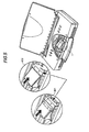
- FIG.5 is an overview of an apparatus capable of loading a plurality of different sorts of function units in a manner wherein exchangeability between units is reserved.
- the apparatus shown in FIG.5 represents an actual apparatus which exchangeably loads a printing head 401 in use for recording onto a recording medium and a scanner head 402 in use for reading an image of originals.
- the apparatus shown in FIG.5 varies its operating functions depending on species of heads loaded on a carriage unit 7, which is one of constituents of the apparatus. If the ink head 401 is, for instance, loaded on that unit, the apparatus is driven so that an inkjet-type printing (line printing) function operates. If the scanner head 402 in use for reading the image pictures is loaded on that unit on the contrary, the apparatus is driven so that a scanner function operates.
- the low battery level is set up so that a minimum electric power at least necessary for capping the printing head can be reserved.
- the scanner head 402 can operate at a lower storage level of the battery than the inkjet head 401 because the scanner head 402 does not require the capping. Namely, a set up of the low battery level being adjusted to the printing operation brings about an inefficient utilization of storage energy with regard to the scanner operation of the same apparatus.
- the low battery level control whereby the scanner operates in the vicinities of the utilization limit of the battery capacity is allowable.
- the printing function operates being driven by the battery on that status set up above, there arises a danger that the battery is excessively discharged to such a storage capacity level wherein capping of the printing head cannot be attained anymore.
- a set up of the low battery level being adjusted to the scanner operation can be regarded as the set up having a danger of causing the operational failures on the printing function involved by the same apparatus.
- US-4,984,185 discloses a system for checking whether the voltage of a battery is sufficient for the load that is to be imposed on it. There may be two or more voltage checking circuits with different reference voltages.
- the disclosed apparatus may be a portable, battery-driven computer and the system checks to see whether the battery has adequate power to drive the logic circuit, a floppy disk drive or a printer, wherein the printer may be prevented from operating if there is insufficient power in the battery.
- the system operates by measuring the voltage across the battery terminals.
- the constitutions mentioned above according to the present invention can solve the mismatching problem which has so far arisen between the species of the operating functions and the levels set up for detecting the low battery state.
- the embodiments deal mainly with a multifunctional apparatus which can operate both a printing function and a scanner function.
- FIG.1 is a block diagram showing both the constituents and an organizational relation between those constituents, which constitute an operation system of the multifunctional apparatus of the embodiments.
- the constituted operation system of this apparatus is governed and controlled by a microprocessor unit (referred to as "MPU” hereinafter) 1 and a read only memory (referred to as “ROM” hereinafter) 2, the latter of which is used for programming operation of the apparatus.
- MPU microprocessor unit
- ROM read only memory
- This multifunctional apparatus of the embodiment includes a power supply unit 3.
- the unit 3 converts a power supply input from an alternating current (referred to as "AC” hereinafter) adapter or from the battery, without inverting into any intervening AC power, directly into new direct current (referred to as “DC” hereinafter) powers having required voltages to output the powers to each of other units.
- FIG.2 illustrates in detail the constituents which relate particularly to the present invention, i.e. constituents of the battery output.
- the unit 3 has a space wherein a battery 201 for driving the multifunctional apparatus of the embodiment is built-in.
- a terminal voltage of the battery 201 is constituted so as to be monitored by a detecting mean 202 of a battery voltage.
- a value detected by the detecting mean 202 is to be sent to a comparator 203, which plays a role of comparing mean.
- the comparing mean 203 compares above-mentioned detected value with a certain threshold value sent from MPU 1 to pass a judgment whether a present status of the battery is on a low battery state or not.
- the apparatus of the embodiment has a random access memory (referred to as "RAM” hereinafter) 5 and a data bus line 6 as controlling and managing means of the data.
- RAM random access memory
- the multifunctional apparatus of the embodiment is structurally equipped with a carriage unit 7, which can load either an ink head 401 or a scanner head 402 thereon, as can be seen from FIG.5.
- the function operated by the multifunctional apparatus concerned is decided by the species of head which is loaded on the carriage 7. Namely, the apparatus concerned is designed so that the apparatus works as a printer if the ink head 401 is loaded on the carriage 7 while the apparatus works as a scanner if the scanner head 402 is loaded on the carriage 7.
- FIG.1 The other constituents of the embodiments beside the cited above are summarized similarly in FIG.1. They are a carriage (referred to as "CR” hereinafter) motor 8, a driver 9 of the same, a line feeding (referred to as “LF” hereinafter) motor 10 to feed the apparatus with media, namely, with white papers which are to be printed by the ink cartridge head 401, with manuscripts of which image pictures are to be read by the scanner head 402, with etc., a driver 11 of the same and an operation unit 12 for users, which is composed of switches, light emitting diodes (referred to as "LED” hereinafter) and so on.
- CR carriage
- LF line feeding
- a driver 11 of the same to feed the apparatus with media, namely, with white papers which are to be printed by the ink cartridge head 401, with manuscripts of which image pictures are to be read by the scanner head 402, with etc.
- a driver 11 of the same and an operation unit 12 for users which is composed of switches, light emitting diodes (referred
- FIG. 3 is a flow chart showing a control operation sequence of the embodiments.
- MPU 1 shown in FIG.1 discriminates first the species of head loaded on the carriage 7 at Step F01 of FIG.3.
- a detecting procedure of the loaded head herein, a detecting mean utilizing an identification (referred to as "I/D” hereinafter) technology as shown in FIG.4 is well known.
- the I/D technology is substantially formed of a discrimination whether certain terminals of various heads are connected with the ground (referred to as "GND” hereinafter) or ungrounded.
- GND ground
- MPU 1 reads the I/D data of the head concerned as a change of a signal propagated along a certain bus line 6.
- the signal output of I/D data exhibits a unity (referred to as "1" hereinafter) state having an output voltage of 5 volts (referred to as "V” hereinafter) if the ink head 401 is loaded on the carriage 7 while the signal output of I/D data is changed to a null (referred to as "0" hereinafter) state having an output voltage of 0 V if the scanner head is loaded.
- the species of the loaded head is discriminated by this signal change.
- a tri-state I/D technology to detect whether a signal output from a certain terminal is plus, zero or minus, is available instead of this bistate I/D technology.
- MPU 1 passes a judgment at Step F02 that the apparatus is just now operating the scanner function, and then prepares a threshold value of the low battery level for scanner use as a comparing value of a comparator mean 203 at Step F03-1.
- MPU 1 passes another judgment at Step F02 that the apparatus concerned is now operating the printer function, and then chooses the threshold value of the low battery level for printer use at Step F03-2.
- the threshold level by which the low battery state is to be detected, varies depending on the species of function modes just operated by the multifunctional apparatus concerned. Namely, during operating the printing function, the apparatus concerned detects the level of the low battery state whereby the reserved capacity can protect the ink head 401 while, during operating the scanner function, the apparatus can control the battery so as to utilize the battery capacity to its discharging limit.
- the control mode for detecting the low battery state should also be changed dependently upon the species of heads.
- the embodiments according to the present invention clarify that a difference in control methods of detecting the low battery level between the printing operation and the scanner operation can substantially solve the mismatch problem which we have so far encountered with so long as a constant threshold level is set up.
- the embodiments mentioned above mainly deal with the apparatus wherein the inkjet head 401 and the scanner head 402 are exchangeably loaded.
- availability of the present invention is not limited to above-mentioned examples.
- the present invention is also available to an apparatus exchangeably loading a plurality of function units of which power dissipations are different from each other and of which lowest power capacity levels necessary for stably operating the functions are different from each other.
- this invention can still be carried out into practice even on an apparatus which exchangeably loads both a thermal head to transcribe an ink by the use of thermal energy and a scanner head.
- I/D detection technologies according to the present invention are not restricted to the example mentioned above. It may be an I/D detection technology of the exchangeably loaded units wherein a code for identification recorded on a recording medium such as a ROM provided on each of units is identified by reading. It may also be an I/D detection technology of the exchangeably loaded units wherein a resistivity of a resistor provided on each of units so as to be resistively different from each other is identified by measurement.
- the present invention is further applicable to other multifunctional apparatus driven by the battery in use for such as office automation beside the mentioned above; for instance, to a notebook-type personal computer, which is equipped with a key-in function, a printing function, recording functions utilizing an HDD, an FDD, a minicompact disk or an MO driver driven by different sorts of motors, a communicating function and with many other functions, and to many other apparatus.
- a notebook-type personal computer which is equipped with a key-in function, a printing function, recording functions utilizing an HDD, an FDD, a minicompact disk or an MO driver driven by different sorts of motors, a communicating function and with many other functions, and to many other apparatus.
- the set up of the low battery level is controlled so that the minimum required power, which is necessary at least for stably operating the functions, is reserved in the battery.
Description
Claims (7)
- A battery-operated apparatus which operates being driven by an electric power supplied from a battery (201) comprising;characterized in that said apparatus further comprisesa detecting means (202) for a low level status of capacity stored in said battery (201), anda control means (1) for terminating an operation of said apparatus corresponding to said low level state of said battery (201 detected by said detecting means (202),
a loading stage (7) exchangeably to load a plurality of units (401, 402) having functions different from each other, wherein lowest levels of capacity stored in said battery necessary for being capable of stably operating said functions are also different from each other;
wherein said control means varies threshold values of said low level state of said battery thereby to terminate said operation of said apparatus depending upon species of said units loaded on said loading stage (7). - The apparatus according to claim 1, further comprising an I/D-means to identify said species of said units (401, 402) loaded on said loading stage (7), wherein said control means (1) varies said threshold values of said low level state of said battery (201) thereby to terminate said operation of said apparatus depending on said I/D-data detected by said I/D-means.
- The apparatus according to claim 1 or 2, wherein said detecting means (202) detects said low level state of said battery (201) depending on a terminal voltage of said battery.
- The apparatus according to any one of the preceding claims, wherein said apparatus is a printer capable of printing operation onto recording media and said units include both a printing head (401) to record data onto recording media and scanner head (402) capable of reading image pictures out of manuscript surfaces.
- The apparatus according to claim 4, wherein said printing-head (401) is an inkjet-type printing head to record data onto recording media surfaces by ejecting ink.
- The apparatus according to claim 5, wherein said control means (1) terminates said operation of said apparatus at a lower level of said capacity stored in said battery (201) when said unit loaded on said loading stage (7) is said scanner head (402), compared with a level of said capacity stored in said battery (201) when said unit loaded on said loading stage is said printing head (401).
- A control method of a battery-operated apparatus, which operates being driven by an electric power supplied from a battery (201) and comprises a loading stage (7) exchangeably to load a plurality of units (401, 402) having functions different from each other wherein lowest stored capacity levels of said battery necessary for being capable of stably operating said functions are also different from each other, comprising the steps:an I/D process step for identifying the species of said units (401, 402) loaded on said loading stage (7), a detecting process step for detecting said low level status of capacity stored in said battery (201), anda terminating process step for terminating said operation of said apparatus depending on said low level status of capacity stored in said battery (201) detected by said detecting process step, wherein said terminating process step varies said threshold values of said low level state of said battery (201) thereby to terminate said operation of said apparatus depending on said species of said units (401, 402) loaded on said loading stage (7).
Applications Claiming Priority (3)
| Application Number | Priority Date | Filing Date | Title |
|---|---|---|---|
| JP18621396 | 1996-07-16 | ||
| JP8186213A JPH1032668A (en) | 1996-07-16 | 1996-07-16 | Multi-functional office automation device |
| JP186213/96 | 1996-07-16 |
Publications (3)
| Publication Number | Publication Date |
|---|---|
| EP0820184A2 EP0820184A2 (en) | 1998-01-21 |
| EP0820184A3 EP0820184A3 (en) | 1999-09-15 |
| EP0820184B1 true EP0820184B1 (en) | 2004-03-03 |
Family
ID=16184356
Family Applications (1)
| Application Number | Title | Priority Date | Filing Date |
|---|---|---|---|
| EP97111063A Expired - Lifetime EP0820184B1 (en) | 1996-07-16 | 1997-07-02 | Multifunctional apparatus and control method for said apparatus |
Country Status (4)
| Country | Link |
|---|---|
| US (1) | US6114837A (en) |
| EP (1) | EP0820184B1 (en) |
| JP (1) | JPH1032668A (en) |
| DE (1) | DE69727863T2 (en) |
Families Citing this family (6)
| Publication number | Priority date | Publication date | Assignee | Title |
|---|---|---|---|---|
| DE69634884T2 (en) * | 1995-04-11 | 2006-04-27 | Canon K.K. | Inkjet recorder with an image reading head |
| JP2001067304A (en) * | 1999-08-24 | 2001-03-16 | Canon Inc | Multi-functional device and identification method of mounted device in the same |
| JP2001246821A (en) | 2000-03-07 | 2001-09-11 | Sony Corp | Machinery of every kind integrated with printer |
| US6851781B2 (en) | 2002-02-20 | 2005-02-08 | Seiko Epson Corporation | Printing apparatus controlling method, printing apparatus controlling program, recording medium for storing printing apparatus controlling program and printing system |
| US7433090B2 (en) * | 2003-01-28 | 2008-10-07 | Murray David K | Print/scan assembly and printer apparatus and methods including the same |
| US6971731B2 (en) * | 2003-06-17 | 2005-12-06 | Hewlett-Packard Development Company, L.P. | Performing power reduction action when average power utilization for inkjet printing a swath exceeds a threshold |
Family Cites Families (8)
| Publication number | Priority date | Publication date | Assignee | Title |
|---|---|---|---|---|
| JPS58116076A (en) * | 1981-12-28 | 1983-07-11 | Toshiba Corp | Detecting circuit for angle of allowance of commutation |
| JPS6375877U (en) * | 1986-11-07 | 1988-05-20 | ||
| JP3060347B2 (en) * | 1992-12-28 | 2000-07-10 | キヤノン株式会社 | Recording device |
| JP3325362B2 (en) * | 1993-01-18 | 2002-09-17 | 株式会社リコー | Facsimile machine |
| US5532825A (en) * | 1993-08-30 | 1996-07-02 | Hewlett-Packard Company | Add-on scanner for existing ink jet printer |
| AUPM478094A0 (en) * | 1994-03-29 | 1994-04-21 | Zhang, Weibin | Scanner |
| JP3604767B2 (en) * | 1994-06-01 | 2004-12-22 | キヤノン株式会社 | Image information processing device |
| JPH08331768A (en) * | 1995-06-02 | 1996-12-13 | Internatl Business Mach Corp <Ibm> | Overdischarge protective circuit for battery |
-
1996
- 1996-07-16 JP JP8186213A patent/JPH1032668A/en not_active Withdrawn
-
1997
- 1997-07-02 US US08/887,424 patent/US6114837A/en not_active Expired - Fee Related
- 1997-07-02 EP EP97111063A patent/EP0820184B1/en not_active Expired - Lifetime
- 1997-07-02 DE DE69727863T patent/DE69727863T2/en not_active Expired - Fee Related
Also Published As
| Publication number | Publication date |
|---|---|
| EP0820184A3 (en) | 1999-09-15 |
| DE69727863D1 (en) | 2004-04-08 |
| US6114837A (en) | 2000-09-05 |
| DE69727863T2 (en) | 2004-08-05 |
| EP0820184A2 (en) | 1998-01-21 |
| JPH1032668A (en) | 1998-02-03 |
Similar Documents
| Publication | Publication Date | Title |
|---|---|---|
| US7293187B2 (en) | Image sensing apparatus and power managing method | |
| US8382223B2 (en) | Image forming apparatus, image formation enabling or disabling method, and computer-readable storage medium | |
| EP0820184B1 (en) | Multifunctional apparatus and control method for said apparatus | |
| CN109334259B (en) | Consumable chip and its communication means, consumable chip and imaging device communication system, method | |
| US6666540B2 (en) | Detection of a print recording material reservoir | |
| US10965122B2 (en) | Information processing apparatus including plurality of power supply units for supplying power to fan | |
| KR100212992B1 (en) | Ink cartridge status detecting method of inkjet printer | |
| US6412900B2 (en) | Recording apparatus having a charging function, and charging method | |
| EP1661711A1 (en) | Image forming apparatus | |
| JP2003072058A (en) | Printer, and device and method for controlling print head mechanism | |
| US4951235A (en) | Option unit detecting apparatus for electronic equipment | |
| JP2010157477A (en) | Led lighting control device, recording device using the same, and led lighting control method | |
| JP3747705B2 (en) | Total ink usage estimation method, host device, printer, ink cartridge | |
| US8542383B2 (en) | Data transfer system for an electronic device, a media processing device, and a control method for a media processing device | |
| JP2003212356A (en) | Printing medium loading device, printing device, and discrimination information setting method of printing medium loading device | |
| KR100558986B1 (en) | Apparatus and method for controlling a reproduction speed of an optical disc based on a remaining battery energy | |
| KR100233674B1 (en) | Apparatus and method for protecting recording head ina multi function product used ink jet process | |
| US20210233573A1 (en) | Electronic device | |
| JP4411018B2 (en) | Recording device | |
| JP2820579B2 (en) | Terminal control device | |
| JPH10217578A (en) | Information processing unit with printer | |
| JP3382391B2 (en) | Low battery detection mechanism provided in recording apparatus and recording apparatus | |
| JP3154913B2 (en) | Printer device | |
| US20090244763A1 (en) | Electronic information storage apparatus, information processing apparatus, image forming apparatus, and computer readable medium | |
| JPH0895442A (en) | Image forming device |
Legal Events
| Date | Code | Title | Description |
|---|---|---|---|
| PUAI | Public reference made under article 153(3) epc to a published international application that has entered the european phase |
Free format text: ORIGINAL CODE: 0009012 |
|
| AK | Designated contracting states |
Kind code of ref document: A2 Designated state(s): DE FR GB IT |
|
| PUAL | Search report despatched |
Free format text: ORIGINAL CODE: 0009013 |
|
| AK | Designated contracting states |
Kind code of ref document: A3 Designated state(s): AT BE CH DE DK ES FI FR GB GR IE IT LI LU MC NL PT SE |
|
| RIC1 | Information provided on ipc code assigned before grant |
Free format text: 6H 04N 1/00 A, 6H 04N 1/04 B |
|
| 17P | Request for examination filed |
Effective date: 20000131 |
|
| AKX | Designation fees paid |
Free format text: DE FR GB IT |
|
| 17Q | First examination report despatched |
Effective date: 20021213 |
|
| GRAH | Despatch of communication of intention to grant a patent |
Free format text: ORIGINAL CODE: EPIDOS IGRA |
|
| GRAS | Grant fee paid |
Free format text: ORIGINAL CODE: EPIDOSNIGR3 |
|
| GRAA | (expected) grant |
Free format text: ORIGINAL CODE: 0009210 |
|
| AK | Designated contracting states |
Kind code of ref document: B1 Designated state(s): DE FR GB IT |
|
| PG25 | Lapsed in a contracting state [announced via postgrant information from national office to epo] |
Ref country code: IT Free format text: LAPSE BECAUSE OF FAILURE TO SUBMIT A TRANSLATION OF THE DESCRIPTION OR TO PAY THE FEE WITHIN THE PRE;WARNING: LAPSES OF ITALIAN PATENTS WITH EFFECTIVE DATE BEFORE 2007 MAY HAVE OCCURRED AT ANY TIME BEFORE 2007. THE CORRECT EFFECTIVE DATE MAY BE DIFFERENT FROM THE ONE RECORDED.SCRIBED TIME-LIMIT Effective date: 20040303 Ref country code: FR Free format text: LAPSE BECAUSE OF FAILURE TO SUBMIT A TRANSLATION OF THE DESCRIPTION OR TO PAY THE FEE WITHIN THE PRESCRIBED TIME-LIMIT Effective date: 20040303 |
|
| REG | Reference to a national code |
Ref country code: GB Ref legal event code: FG4D |
|
| REF | Corresponds to: |
Ref document number: 69727863 Country of ref document: DE Date of ref document: 20040408 Kind code of ref document: P |
|
| PLBE | No opposition filed within time limit |
Free format text: ORIGINAL CODE: 0009261 |
|
| STAA | Information on the status of an ep patent application or granted ep patent |
Free format text: STATUS: NO OPPOSITION FILED WITHIN TIME LIMIT |
|
| EN | Fr: translation not filed | ||
| 26N | No opposition filed |
Effective date: 20041206 |
|
| PGFP | Annual fee paid to national office [announced via postgrant information from national office to epo] |
Ref country code: DE Payment date: 20070628 Year of fee payment: 11 |
|
| PGFP | Annual fee paid to national office [announced via postgrant information from national office to epo] |
Ref country code: GB Payment date: 20070627 Year of fee payment: 11 |
|
| GBPC | Gb: european patent ceased through non-payment of renewal fee |
Effective date: 20080702 |
|
| PG25 | Lapsed in a contracting state [announced via postgrant information from national office to epo] |
Ref country code: DE Free format text: LAPSE BECAUSE OF NON-PAYMENT OF DUE FEES Effective date: 20090203 |
|
| PG25 | Lapsed in a contracting state [announced via postgrant information from national office to epo] |
Ref country code: GB Free format text: LAPSE BECAUSE OF NON-PAYMENT OF DUE FEES Effective date: 20080702 |