EP0820004A1 - Druckersystem, Druckertreiber und Drucker - Google Patents
Druckersystem, Druckertreiber und Drucker Download PDFInfo
- Publication number
- EP0820004A1 EP0820004A1 EP97305382A EP97305382A EP0820004A1 EP 0820004 A1 EP0820004 A1 EP 0820004A1 EP 97305382 A EP97305382 A EP 97305382A EP 97305382 A EP97305382 A EP 97305382A EP 0820004 A1 EP0820004 A1 EP 0820004A1
- Authority
- EP
- European Patent Office
- Prior art keywords
- printer
- job data
- intermediate code
- level
- plotting
- Prior art date
- Legal status (The legal status is an assumption and is not a legal conclusion. Google has not performed a legal analysis and makes no representation as to the accuracy of the status listed.)
- Granted
Links
Images


Classifications
-
- G—PHYSICS
- G06—COMPUTING OR CALCULATING; COUNTING
- G06F—ELECTRIC DIGITAL DATA PROCESSING
- G06F3/00—Input arrangements for transferring data to be processed into a form capable of being handled by the computer; Output arrangements for transferring data from processing unit to output unit, e.g. interface arrangements
- G06F3/12—Digital output to print unit, e.g. line printer, chain printer
- G06F3/1297—Printer code translation, conversion, emulation, compression; Configuration of printer parameters
-
- G—PHYSICS
- G06—COMPUTING OR CALCULATING; COUNTING
- G06K—GRAPHICAL DATA READING; PRESENTATION OF DATA; RECORD CARRIERS; HANDLING RECORD CARRIERS
- G06K15/00—Arrangements for producing a permanent visual presentation of the output data, e.g. computer output printers
-
- G—PHYSICS
- G06—COMPUTING OR CALCULATING; COUNTING
- G06K—GRAPHICAL DATA READING; PRESENTATION OF DATA; RECORD CARRIERS; HANDLING RECORD CARRIERS
- G06K2215/00—Arrangements for producing a permanent visual presentation of the output data
- G06K2215/0002—Handling the output data
- G06K2215/0005—Accepting output data; Preparing data for the controlling system
- G06K2215/0011—Accepting output data; Preparing data for the controlling system characterised by a particular command or data flow, e.g. Page Description Language, configuration commands
Definitions
- the present invention relates to a print system including a host computer and a printer connected with the host computer and, in particular, to an improvement in a print speedup technology suitable for a print system using a page printer.
- a controller employed in the page printer includes a high-power CPU and a mass storage memory and, in this respect, the controller is more powerful that the host computer.
- the controller of the page printer does not translate one or more plotting commands from a host computer directly into one or more bit map images but allows an intermediate code to intervene in the middle of translation from the plotting commands to the bit map images, thereby being able not only to simplify the next and following operations of translation into the bit map images but also to facilitate the conversion of the plotting commands free from the detailed characteristics of the print engine, so that the efficiency of-the whole print processing can be improved. Therefore, in the controller of the page printer, a module which interprets a plotting command and creates an intermediate code corresponding to the plotting command is clearly separate from a module which interprets the thus created intermediate code and creates a page of bit map images.
- a print system which includes a host computer and a printer connected with the host computer.
- the host computer includes a printer driver which is used to generate print job data including one or more plotting commands to be given to the printer, while the printer driver further includes intermediate level job data generating means used to generate intermediate level print job data including plotting commands at least part of which are expressed in the format of a first intermediate code.
- the printer includes intermediate code conversion means which is used to receive intermediate level print job data and converts the plotting commands of the intermediate level job data into a second intermediate code, and third conversion means which is used to convert the second intermediate code into bit image data for printing.
- the host computer in the host computer, part or all of the plotting commands are converted to the intermediate code format before being transmitted to the printer. Therefore, in the printer, there can be omitted a processing which converts the plotting commands written in a high-level language to the intermediate code.
- the intermediate code generation processing which has been conventionally performed only in the printer, can be shared by the host computer, especially when the memory or CPU of the host computer has capabilities to spare, and the printing speed of the printer can be enhanced.
- the printer driver further may include high-level job data generation means used to generate high-level print job data in which the plotting commands thereof are all expressed in a high-level printer control language, and mode select means used to select one of the intermediate level job data generation means and the high-level job data generation means.
- the printer further may include graphics means which is used to convert the plotting commands expressed in the high-level printer control language to the second intermediate code.
- two operation modes can be used selectively on a case-by-case basis: that is, an operation mode in which all the plotting commands with respect to the printer are expressed in the high-level printer control language as in the prior art; and, an operation mode in which the plotting commands are in part or wholly converted to the intermediate code.
- selection of one of the two operation modes can be decided automatically.
- the operation mode can be selected automatically by synthetically considering the kinds of application programs, the capabilities of the printer, and the capabilities of the host computer.
- the operation mode may be decided according to a print job unit; or, a page unit, a band unit, or a plotting command unit; or, an application program unit.
- the print job data can also be formed such that it includes specification information for specifying which plotting commands are converted to the intermediate code. For example, when all the plotting commands are converted to the intermediate codes, the print job data can declare in the head portion thereof to the effect that all the plotting commands are converted to the intermediate codes. Also, when only the specific pages, specific bands, or specific commands are converted to the intermediate codes, the declaration to this effect can be set in the head of the specific pages, bands or commands. Such declaration, that is, such specification information, can be described in the printer control language.
- the first intermediate code to be generated by the printer driver and the second intermediate code to be generated by the printer be in the same format.
- the first intermediate code must include bit image data on the individual characters to be plotted and on the individual images to be plotted.
- bit image data is managed at a different storage location from the intermediate code and, therefore, the second intermediate code does not include such bit image data.
- Fig. 1 shows the overall structure of an embodiment of a print system according to the invention.
- the present print system includes a host computer 1 and a page printer 3 connected to the host computer 1.
- an application program 5 notifies the start of a new print job to a plotting module (which is hereinafter referred to as "an application programming interface (API) module") 8 provided within an operating system (OS) 7, and sends the call of the plotting function of the API to the API module 8.
- the API module 8 sends a printer driver 9 the call of the plotting function of the printer driver 9 (which is hereinafter referred to as "a device driver interface (DDI) call").
- a printer driver 9 the call of the plotting function of the printer driver 9 (which is hereinafter referred to as "a device driver interface (DDI) call”).
- DPI device driver interface
- the printer driver 9 converts the DDI call into a print command in an output format which can be recognized by the page printer 3.
- the output format includes two kinds of output formats. One of them is a high-level language which is generally referred to as a printer control language and, in the present embodiment, this corresponds to a Page Description Language (PDL).
- PDL Page Description Language
- the other output format is an intermediate (IM) code which is described in an Intermediate Language (IML).
- This intermediate code is basically the same format as an intermediate code which is generated from PDL by a controller 11 provided in the page printer 3, but they are a little different in the details from each other.
- the intermediate code to be generated by the printer driver 9 is referred to as a driver intermediate (DIM) code
- the intermediate code to be generated by the page printer 3 is referred to as a printer intermediate (PIM) code.
- the DIM code is different from the PIM code mainly in that it includes image bit map data on characters and bit images. That is, when a certain band, with characters and bit images drawn therein, is described in an intermediate code, within the printer, the bit map data on the respective characters and bit images are placed in other memory areas than the PIM code, while pointers to the respective characters and bit images in these memory areas are described in the PIM code.
- the DIM code there are placed not only the characters and bit images but also the bit map data on such characters and bit images. In this case, in order to avoid the repetition of the bit map data, for example, the following format can be employed.
- bit map data on the characters and bit images are placed or registered in the DIM code together with the identification numbers and the size specifications thereof and, next, the identification numbers of the characters and bit images, the coordinates thereof within the band, the specifications of the actually used portions of the thus registered bit map data, and the like are described. After that, each time the same characters and bit images appear again within the same band, the identification numbers of the characters and bit images, the coordinates thereof within the band, the specifications of the actually used portions of the thus registered bit map data are described.
- the PIM code within a printer supports a great variety of plotting functions.
- the DIM code must be matched to the function of the DDI that is supplied by the OS 7 and, therefore, if the function of the DDI is more limited than the function of the PIM code, for example, in the passes, graphics parameters, kinds of coordinate conversion function calls and the like, then the function of the DIM code is similarly more limited than the function of the PIM code in the above-mentioned respects.
- the print command from the printer driver 9 is sent through the OS 7 to the printer 3.
- the controller 11 interprets the print command and converts it into a PIM code.
- the controller 11 interprets the PDL command and converts it into a PIM code according to the same procedure as a conventional printer follows.
- the controller 11 on receipt of a DIM code, the controller 11 generates a PIM code by means of very simple conversion (that is, a conversion which merely cancels the above-mentioned differences). Therefore, the amount of processing of the controller 11 is very small when it receives the DIM code.
- the controller 11 stores the thus generated PIM code into the intermediate code buffer 13. Also, in synchronization with the operation of the print engine 17, the controller 11 creates bit image data from the PIM code stored in the intermediate code buffer 13 and develops it to the image buffer 15. Here, under a specific condition that the bit map data is more advantageous than the PIM code in the amount of memory required and/or processing speed, the controller 11 pre-develops the PIM code to the bit map image before it develops the same to the image buffer 15.
- the print engine 17 reads out the bit map image from the image buffer 15 and prints it on a printing sheet.
- the page printer 3 may include a receive buffer which is capable of provisionally storing a print command from the host computer 1.
- Fig. 2 shows the functional structure of the printer driver 9 included in the host computer 1.
- "to decide a page mode” means to decide whether the output format of a print command to be output to the printer is a PDL format or a DIM code format.
- a mode to output the print command in the PDL format is referred to as a "printer page mode”
- a mode to output the print command in the DIM code format is referred to as a "driver page mode”.
- a method for deciding the page mode will be described in detail later.
- the job data generation module 25 executes a plotting processing which corresponds to a DDI call delivered from the system interface 23 and, as a result of this, a print command chain relating to a print job (which is hereinafter referred to as job data) is generated in such format as shown in Fig. 3 (A).
- the job data shown in Fig. 3 (A) starts with a job start declaration 41, and a language specify command 43 and a printer initialize command 45 follow sequentially after the job start declaration 41. After that, plotting commands 47 in pages follow, while a page eject command 49 is added to the end of each of the plotting commands 47 in the -respective pages.
- a job end declaration 51 is placed after the last plotting command 47 in the last page, which ends the job data.
- the first job start declaration 41, language specify command 43 and the last job end declaration 51 are expressed in a high-level language called a job language which is independent of a printer control language.
- the language specify command 43 specifies a printer control language to be used in the present job data and, in the present embodiment, a given PDL is specified as the language specify command 43.
- Commands 45 to 49 following the language specify command 43 are respectively expressed in a given PDL specified by the language specify command 43.
- the printer initialize command 45 is used to initialize the environment or state of the printer.
- the printer initialize command 45 there is also included the specification of a page mode and, here, a printer page mode is specified.
- Fig. 3 (B) shows an example of the plotting command that is expressed in the IMM call and, in this example, a page is divided into one or more bands and the plotting command 55 of each band is expressed in the IMM call.
- band number declarations 53 which show the start of the respective bands. The band number declarations 53 are respectively expressed in the PDL.
- the job data from the IMM driver 27 is delivered through shared memory 29 to a replay module 31.
- delivery of the job data to the replay module 31 is basically executed through the shared memory 29 but, in the case of the job data having a large record size, the job data is arranged as a file and the name of the file is written into the shared memory 29.
- the replay module 31 passes-therethrough the portions of the job data that are expressed in the job language and PDL, that is, the job start declaration 41, language specify command 43, printer initialize command 45, band number declaration 53 and page eject command 49 respectively shown in Figs. 3 (A) and (B), as they are, and writes them into the spooler 35.
- the replay module 31 calls the plotting function of the IMM module 33.
- the plotting function of the IMM module 33 converts the present plotting command 55 to a DIM code (that is, a driver intermediate code).
- Fig. 3 (C) shows an example of a plotting command 61 included in each of the bands and converted to the DIM code and, to the head of the plotting command 61, there is attached a declaration 59 indicating that the plotting command 61 is an intermediate code (that is, binary data).
- This intermediate code declaration 59 is expressed in the PDL.
- Fig. 4 shows the functional structure of the controller 11 of the printer 3.
- a language interpret part 81 interprets a command included in the job data and expressed in a job language and PDL and, in accordance with the interpretation result, calls the plotting function of a graphics module (which is hereinafter referred to as "GRM").
- GRM graphics module
- the GRM 83 has a function to generate a PIM code (a printer intermediate code) in accordance with a plotting command expressed in the PDL. Also, the intermediate code conversion part 85 is a function which is added to the GRM 83 in order to convert the DIM code to the PIM code.
- a processing for converting the DIM code to the PIM code is very simple when compared with a processing to be performed by the GRM 83, as was described before.
- the GRM 83 generates a PIM code.
- the intermediate code conversion part 85 generates the PIM code from the DIM code included in the job data by means of simple conversion.
- the DIM code may also be pre-developed to the bit map data.
- the generated PIM code is delivered from the GRM 83 to a PIM code register & develop part 87.
- the PIM code register & develop part 87 registers the PIM code in the intermediate code buffer 13 and, in synchronization with the operation of the print engine 17, reads out the PIM code from the intermediate code buffer 13 and develops a bit map image on the image buffer 15 in accordance with the read-out PIM code.
- Fig. 5 shows a flow chart of the overall flow of the processing to be performed by the printer driver 9.
- the printer driver 9 receives the DDI call from the API 8 (S1), if the initialize function of the driver 9 is invoked by the present DDI call (Y in S2), then not only is page mode decided (S3) but also banding (S4) is decided in the present initialize processing. These decisions are executed according to the flows that are respectively shown in Fig. 6.
- evaluation points are calculated with respect to the printer page mode and driver page mode, and page mode is selected which has the greater evaluation points (S11, S12).
- the calculation of the evaluation points is executed according to an evaluation point table which, as shown in Fig. 7, shows the evaluation points of the respective modes with respect to various parameters.
- an application type is used to distinguish the types of the applications 5 from each other. That is, whether the application 5 is an application of a type that is mainly used to handle characters (such as a text editor, a word processor, or the like), a type that is mainly used to handle graphics forms (such as CAD, draw-system graphics, or the like), or a type that is mainly used to handle images (such as photo-retouch, paint-system graphics, or the like).
- the parameters can be evaluated in the following manner. That is, when the quantity of data to be processed is large or the power of a printer is low, the evaluation point of the driver page mode is high. On the other hand, when the quantity of data to be processed is small or the capability of a host computer is low, the evaluation point of the printer page mode is high.
- the evaluation points of these parameters are summed up for each of the two modes and the sum values of the evaluation points of the two modes are compared with each other. The mode that is found higher in the sum value is selected.
- Fig. 3 (D) in this technique, it is arranged that certain plotting commands 65 and 69 in one band are expressed in the IMM call, the other command 67 is expressed in the PDL and, after that, as shown in Fig. 3 (E), the IMM calls 65 and 69 are converted toa DIM code 75.
- the command 67 when there is included a command to plot characters using the printer fonts, the command 67 is expressed in the PDL as conventionally and thus the command 67 is allowed to exist together with the plotting commands 65 and 69 expressed in the IMM call.
- the portion of the command to plot characters using the printer fonts can be processed only at the same speed as the conventional processing speed, the other portions thereof are allowed to generate intermediate codes on the printer driver side, with the result that the present print job as a whole can be processed at high speed.
- the banding decision processing (S4) is executed.
- the number of bytes of a memory necessary to store DIM codes corresponding to one page is estimated, the estimated byte number is set in a variable P, and the initial value 1 of the band number is set in a variable n (S13).
- n a P byte memory can be actually secured or not.
- an unbanding processing that is, a page is not divided into two or more bands but is processed as a band
- S16 the larger the size of the P byte is, the less frequently the plotting element is divided, which reduces the number of times of replay to thereby reduce the driver processing time, resulting in improved performance of the overall processing.
- the main operation of the plotting processing is assigned to the job generation module 25 or IMM driver 27. That is, if the mode is the printer page mode, then the plotting function of the job generation module 25 is called by the plotting DDI call, plotting commands in the PDL are thereby generated, and the thus generated PDL commands are respectively written into the spooler 35 in pages (S6).
- the function of the IMM driver 27 is invoked by the plotting DDI call, a function call for the IMM module 33 is thereby generated, and the thus generated function call is then written into the shared memory 29 (S7). Also, asynchronously with the writing of the function call into the shared memory 29, in response to an IMM function call within the shared memory 29, the replay module 31 calls the IMM module 33, generates a DIM code, and writes the thus generated DIM code into the spooler 35 (S8). The above-mentioned processing is performed repeatedly until a DDI call indicating the end of the job appears (S9).
- Fig. 8 shows the details of the above-mentioned processing to be performed in Step S7 shown in Fig. 5. This processing is executed by the job data generation module 25 and IMM driver 27 shown in Fig. 2.
- a DDI call for initialization of the print job is received (S21).
- a command for initialization of the function of the IMM module 33 is received (S21).
- the start declaration 41, language specify command 43 and printer initialize command 45 (including the specification of the page mode) respectively shown in Fig. 3 (A) (S22 to S25), and they are written into the shared memory 29 (S28).
- a DDI call for the plotting processing of each page is received.
- the plotting command 55 in the form of an IMM call and band number declarations 53 and 57 expressed in the PDL, which are respectively shown in Fig.
- Fig. 9 shows the details of the processing to be performed in Step S8 shown in Fig. 5. This processing is executed by the replay module 31 and IMM module 33 shown in Fig. 2.
- the replay module 31 reads out job data from the shared memory 29 (S31) and checks whether or not a command included in the thus read-out job data is a command described in a job language or a command described in the PDL (S32). Then, if it is found that the command in the job data is described in the job language or PDL, then the command, as it is, is output to the spooler 35 (Y in S32). On the other hand, for an IMM call in the job data, there is invoked a plotting function which is stored in the IMM module 33 and corresponds to the IMM call (S33), and a plotting processing is executed using the parameters of the present IMM call (S34).
- bit map data on characters and bit images are developed onto a previously secured page memory (or band memory) (S34) and, in bands, there are generated such plotting commands 61 in the form of DIM codes as shown in Fig. 3 (C) (S35).
- the respective bands may be pre-developed to the bit map images not in the form of DIM codes.
- the thus generated DIM code plotting commands 61 are output to the spooler 35 (S36).
- the above-mentioned processing is performed repeatedly until the last portion of the job data is finished (S37).
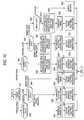
- Fig. 10 shows the details of the processing to be performed by the language interpret part 81 of the controller 11 provided within the printer, which is already shown in Fig. 4.
- each plotting command is a command to plot characters or not (that is, whether it includes character data or not) (S42), or a command to plot bit images or not (whether it includes binary data or not) (S43), or a command to plot graphics (figures) or not (whether it includes graphics data or not), that is, (whether it includes neither character data nor binary data or not).
- the bit map data of the characters are generated (S44) and, then a character plotting instruction is given to GRM 83 (S45). If the command to plot graphics is received, then the plotting control point of the graphics is set (S46) and, after that, a graphics plotting instruction is given to the GRM 83 (S47). If the command to plot bit images is received, then the bit map data of the bit images is created (S48) and, then-an image plotting instruction is given to the GRM 83 (S49). In accordance with such plotting instruction, the GRM 83 generates a PIM code and then writes the same into the intermediate code buffer 13.
- the plotting command in the form of a DIM code is output to the GRM 83 (S62).
- the GRM 83 invokes the intermediate code convert part 85 to thereby convert the DIM code to the PIM code. This conversion processing is so simple that it can be executed at a high speed.
- the printer page mode or driver page mode is selected and, for the driver page mode, the plotting command is converted to the intermediate code by the printer driver before it is supplied to the printer.
- the plotting commands of all pages are expressed in the intermediate code form.
- the invention is not always limited to this but, for example, some pages may be expressed in the intermediate code, whereas the other pages may be expressed in the PDL. That is, the intermediate code conversion processing may be controlled in pages. Or, the intermediate code conversion processing may be controlled in applications.
- the above conversion processing can be controlled in bands or in commands.
- the processing is controlled in bands, for example, the plotting commands of certain bands are converted to the IMM code as shown in Figs. 3 (B) and (C) before they are converted to the DIM code, whereas the plotting commands of the other bands are expressed in the PDL.
- the processing is controlled in commands, at first, as shown in Fig. 3 (D), certain commands 65 and 69 in a band are expressed in the IMM call and the other band 67 is expressed in the PDL and, then, as shown in Fig. 3 (E), the IMM calls 65 and 69 are converted to the DIM code 75.
- a clipping area corresponding to the range of a physical band to be processed is firstly set (S55)
- the plotting control point of the graphics is then set (S58) and, after that, a graphics plotting instruction is given to the GRM 83 (S59).
- a clipping area corresponding to the range of a physical band to be processed is firstly set (S63)
- the bit map data on the bit images is created (S60) and, after that, an image plotting instruction is given to the GRM 83 (S61).
- the command expressed in the intermediate code is received, then the command, as it is, is delivered to the GRM 83 (S62).
Landscapes
- Engineering & Computer Science (AREA)
- Theoretical Computer Science (AREA)
- General Engineering & Computer Science (AREA)
- Physics & Mathematics (AREA)
- General Physics & Mathematics (AREA)
- Human Computer Interaction (AREA)
- Record Information Processing For Printing (AREA)
- Accessory Devices And Overall Control Thereof (AREA)
Applications Claiming Priority (3)
| Application Number | Priority Date | Filing Date | Title |
|---|---|---|---|
| JP19084996A JP3209102B2 (ja) | 1996-07-19 | 1996-07-19 | プリントシステム、プリンタドライバ及びプリンタ |
| JP19084996 | 1996-07-19 | ||
| JP190849/96 | 1996-07-19 |
Publications (2)
| Publication Number | Publication Date |
|---|---|
| EP0820004A1 true EP0820004A1 (de) | 1998-01-21 |
| EP0820004B1 EP0820004B1 (de) | 2002-04-10 |
Family
ID=16264805
Family Applications (1)
| Application Number | Title | Priority Date | Filing Date |
|---|---|---|---|
| EP19970305382 Expired - Lifetime EP0820004B1 (de) | 1996-07-19 | 1997-07-18 | Druckersystem, Druckverfahren, Druckertreiber und Drucker |
Country Status (3)
| Country | Link |
|---|---|
| EP (1) | EP0820004B1 (de) |
| JP (1) | JP3209102B2 (de) |
| DE (1) | DE69711775T2 (de) |
Cited By (11)
| Publication number | Priority date | Publication date | Assignee | Title |
|---|---|---|---|---|
| EP0935187A3 (de) * | 1998-02-05 | 2000-08-16 | Canon Kabushiki Kaisha | Druckdatenerzeugung und Drucksteuerungsverfahren und -gerät |
| EP1098265A3 (de) * | 1999-11-05 | 2002-03-20 | Claricom Limited | Verpackung von verderblichen Produkten |
| EP1071036A3 (de) * | 1999-07-22 | 2002-08-28 | Seiko Epson Corporation | Ausdruck aus verschiedenen Druckersteuerungssprachen |
| EP1098242A3 (de) * | 1999-11-02 | 2005-08-03 | Canon Kabushiki Kaisha | Informationsprozessor, Verfahren um Information zu verarbeiten sowie Speichermedium, um durch ein Rechner lesbares Programm zu speichern |
| GB2387938B (en) * | 2002-01-30 | 2005-10-26 | Hewlett Packard Co | Conversion from page description language and conversion to printer language |
| EP1189134A3 (de) * | 2000-09-18 | 2006-02-15 | Canon Kabushiki Kaisha | Datenverarbeitungsgerät, Druckersystem, und Befehlserzeugungsverfahren |
| US7054020B2 (en) * | 2000-01-24 | 2006-05-30 | Seiko Epson Corporation | Print job management system |
| US7110129B2 (en) * | 2001-01-26 | 2006-09-19 | International Business Machines Corporation | Method, system, and program for responding to an acknowledgement request from a printer driver |
| US7172121B2 (en) | 2000-11-03 | 2007-02-06 | Claricom Limited | System and method for applying codes onto packaged products |
| EP1329801A3 (de) * | 2002-01-17 | 2007-03-14 | Canon Kabushiki Kaisha | Druckersystem und Drucker |
| US7973963B2 (en) | 1998-03-27 | 2011-07-05 | Canon Kabushiki Kaisha | Image forming apparatus, method of controlling image forming apparatus, and memory medium for storing computer program for executing method, with function program providing API |
Families Citing this family (4)
| Publication number | Priority date | Publication date | Assignee | Title |
|---|---|---|---|---|
| JP2008312204A (ja) * | 2008-06-09 | 2008-12-25 | Canon Inc | 画像処理装置、画像処理装置の制御方法、および記憶媒体 |
| JP4522476B2 (ja) * | 2009-04-24 | 2010-08-11 | キヤノン株式会社 | 画像処理装置、画像処理装置の制御方法、および記憶媒体 |
| JP4642927B2 (ja) * | 2010-04-12 | 2011-03-02 | キヤノン株式会社 | 画像処理装置、画像処理装置の制御方法、および記憶媒体 |
| JP2011078114A (ja) * | 2010-11-10 | 2011-04-14 | Canon Inc | 画像処理装置、画像処理装置の制御方法、およびプログラム |
Citations (2)
| Publication number | Priority date | Publication date | Assignee | Title |
|---|---|---|---|---|
| WO1990012372A1 (en) * | 1989-04-11 | 1990-10-18 | Eastman Kodak Company | Computer output printer with plotter emulation |
| EP0659570A2 (de) * | 1993-12-27 | 1995-06-28 | Canon Kabushiki Kaisha | Mustererzeugungsgerät und Mustererzeugungsmethode |
-
1996
- 1996-07-19 JP JP19084996A patent/JP3209102B2/ja not_active Expired - Lifetime
-
1997
- 1997-07-18 DE DE1997611775 patent/DE69711775T2/de not_active Expired - Lifetime
- 1997-07-18 EP EP19970305382 patent/EP0820004B1/de not_active Expired - Lifetime
Patent Citations (2)
| Publication number | Priority date | Publication date | Assignee | Title |
|---|---|---|---|---|
| WO1990012372A1 (en) * | 1989-04-11 | 1990-10-18 | Eastman Kodak Company | Computer output printer with plotter emulation |
| EP0659570A2 (de) * | 1993-12-27 | 1995-06-28 | Canon Kabushiki Kaisha | Mustererzeugungsgerät und Mustererzeugungsmethode |
Cited By (21)
| Publication number | Priority date | Publication date | Assignee | Title |
|---|---|---|---|---|
| EP0935187A3 (de) * | 1998-02-05 | 2000-08-16 | Canon Kabushiki Kaisha | Druckdatenerzeugung und Drucksteuerungsverfahren und -gerät |
| US6734986B1 (en) | 1998-02-05 | 2004-05-11 | Canon Kabushiki Kaisha | Print control apparatus, print data generating apparatus, print control method, print data generating method, and storage medium |
| US8300253B2 (en) | 1998-03-27 | 2012-10-30 | Canon Kabushika Kaisha | Image forming apparatus, method of controlling image forming apparatus, and memory medium for storing computer program for executing method, with interpreter for control programs that are provided for execution on OS-independent platform |
| US7973963B2 (en) | 1998-03-27 | 2011-07-05 | Canon Kabushiki Kaisha | Image forming apparatus, method of controlling image forming apparatus, and memory medium for storing computer program for executing method, with function program providing API |
| EP1071036A3 (de) * | 1999-07-22 | 2002-08-28 | Seiko Epson Corporation | Ausdruck aus verschiedenen Druckersteuerungssprachen |
| US7443519B1 (en) | 1999-07-22 | 2008-10-28 | Seiko Epson Corporation | Printer system flexibly compatible with plurality of printer control languages (PCL) using intermediate and raster codes |
| US7154627B2 (en) | 1999-11-02 | 2006-12-26 | Canon Kabushiki Kaisha | Information processor, method for processing information and memory medium for storing program readable by computer |
| US7307749B2 (en) | 1999-11-02 | 2007-12-11 | Canon Kabushiki Kaisha | Information processor, method for processing information and memory medium for storing program readable by computer |
| EP1098242A3 (de) * | 1999-11-02 | 2005-08-03 | Canon Kabushiki Kaisha | Informationsprozessor, Verfahren um Information zu verarbeiten sowie Speichermedium, um durch ein Rechner lesbares Programm zu speichern |
| US7500613B2 (en) | 1999-11-05 | 2009-03-10 | Claricom Limited | System and method for applying codes onto packaged products |
| EP1098265A3 (de) * | 1999-11-05 | 2002-03-20 | Claricom Limited | Verpackung von verderblichen Produkten |
| US6732928B1 (en) | 1999-11-05 | 2004-05-11 | Clarion Limited | System and method for applying codes onto packaged products |
| US7054020B2 (en) * | 2000-01-24 | 2006-05-30 | Seiko Epson Corporation | Print job management system |
| US7170619B2 (en) | 2000-09-18 | 2007-01-30 | Canon Kabushiki Kaisha | Information processing apparatus, printing system, and command generating method |
| EP1189134A3 (de) * | 2000-09-18 | 2006-02-15 | Canon Kabushiki Kaisha | Datenverarbeitungsgerät, Druckersystem, und Befehlserzeugungsverfahren |
| US7172121B2 (en) | 2000-11-03 | 2007-02-06 | Claricom Limited | System and method for applying codes onto packaged products |
| US7110129B2 (en) * | 2001-01-26 | 2006-09-19 | International Business Machines Corporation | Method, system, and program for responding to an acknowledgement request from a printer driver |
| US7248384B2 (en) * | 2001-01-26 | 2007-07-24 | International Business Machines Corporation | Method, system, and program for responding to an acknowledgement request from a printer driver |
| EP1329801A3 (de) * | 2002-01-17 | 2007-03-14 | Canon Kabushiki Kaisha | Druckersystem und Drucker |
| US7229224B2 (en) | 2002-01-17 | 2007-06-12 | Canon Kabushiki Kaisha | Printing system and printing apparatus |
| GB2387938B (en) * | 2002-01-30 | 2005-10-26 | Hewlett Packard Co | Conversion from page description language and conversion to printer language |
Also Published As
| Publication number | Publication date |
|---|---|
| JPH1040031A (ja) | 1998-02-13 |
| JP3209102B2 (ja) | 2001-09-17 |
| DE69711775T2 (de) | 2002-08-08 |
| EP0820004B1 (de) | 2002-04-10 |
| DE69711775D1 (de) | 2002-05-16 |
Similar Documents
| Publication | Publication Date | Title |
|---|---|---|
| US6665081B1 (en) | Print system printer driver and printer | |
| EP0820004B1 (de) | Druckersystem, Druckverfahren, Druckertreiber und Drucker | |
| EP0750250A1 (de) | Druckersteuerungsgerät und -verfahren,Datenverarbeitungsgerät und -verfahren sowie das Steuerungsprogramm speicherndes Speichermedium | |
| EP0772115B1 (de) | System, Ausgabegerät, Verfahren, und rechnerlesbares Medium, die zum Steuern eines Druckers einen gespaltenen Druckertreiber verwenden | |
| US6476938B1 (en) | Print control system and method | |
| US7103833B1 (en) | Image processing apparatus, output apparatus, image processing system and image processing method | |
| EP0684546B1 (de) | Drucker, Druckersystem und Verfahren, um die Zeichenbetriebsmittel des Druckerssystems zu erfahren | |
| US5970221A (en) | Printer with reduced memory | |
| US20040105102A1 (en) | Information processing apparatus, information processing method and printing control method | |
| EP0870277B1 (de) | Bilderzeugung für seitendrucker | |
| US6310693B1 (en) | Printing control apparatus and method, and printing system for reducing processing overhead | |
| US20040004739A1 (en) | Printer system, printer, printer control method | |
| KR970010375B1 (ko) | 밴드 오버런 에러를 방지하는 페이지 프린터의 밴드 프린팅방법 | |
| KR100223650B1 (ko) | 프린트 데이타 처리방법 | |
| US7443519B1 (en) | Printer system flexibly compatible with plurality of printer control languages (PCL) using intermediate and raster codes | |
| EP0752641B1 (de) | Steuerung von Druckerauflösung und/oder Graustufen | |
| US20040120007A1 (en) | Method and apparatus for forming a display list | |
| EP0675428B1 (de) | Druckersystem und Verfahren um grafische Daten zu drucken | |
| US20030098988A1 (en) | Fast printing apparatus and method thereof | |
| JP2000207147A (ja) | 印刷デ―タ転送システム | |
| US6281985B1 (en) | Print control apparatus, print control method, and memory medium | |
| JP3432205B2 (ja) | 情報処理装置およびデータ処理方法および印刷制御システム | |
| JPH0789153A (ja) | プリンタシステム | |
| JP2000033730A (ja) | 印刷装置とその制御方法及び印刷システム | |
| JP4325339B2 (ja) | 印刷システム、ホストコンピュータ及びプリンタドライバ |
Legal Events
| Date | Code | Title | Description |
|---|---|---|---|
| PUAI | Public reference made under article 153(3) epc to a published international application that has entered the european phase |
Free format text: ORIGINAL CODE: 0009012 |
|
| AK | Designated contracting states |
Kind code of ref document: A1 Designated state(s): DE FR GB |
|
| AX | Request for extension of the european patent |
Free format text: AL;LT;LV;RO;SI |
|
| 17P | Request for examination filed |
Effective date: 19980710 |
|
| AKX | Designation fees paid |
Free format text: DE FR GB |
|
| RBV | Designated contracting states (corrected) |
Designated state(s): DE FR GB |
|
| 17Q | First examination report despatched |
Effective date: 20001009 |
|
| GRAG | Despatch of communication of intention to grant |
Free format text: ORIGINAL CODE: EPIDOS AGRA |
|
| RTI1 | Title (correction) |
Free format text: PRINT SYSTEM, PRINT METHOD, PRINTER DRIVER AND PRINTER |
|
| GRAG | Despatch of communication of intention to grant |
Free format text: ORIGINAL CODE: EPIDOS AGRA |
|
| GRAH | Despatch of communication of intention to grant a patent |
Free format text: ORIGINAL CODE: EPIDOS IGRA |
|
| GRAG | Despatch of communication of intention to grant |
Free format text: ORIGINAL CODE: EPIDOS AGRA |
|
| GRAH | Despatch of communication of intention to grant a patent |
Free format text: ORIGINAL CODE: EPIDOS IGRA |
|
| GRAH | Despatch of communication of intention to grant a patent |
Free format text: ORIGINAL CODE: EPIDOS IGRA |
|
| REG | Reference to a national code |
Ref country code: GB Ref legal event code: IF02 |
|
| GRAA | (expected) grant |
Free format text: ORIGINAL CODE: 0009210 |
|
| AK | Designated contracting states |
Kind code of ref document: B1 Designated state(s): DE FR GB |
|
| REF | Corresponds to: |
Ref document number: 69711775 Country of ref document: DE Date of ref document: 20020516 |
|
| ET | Fr: translation filed | ||
| PLBE | No opposition filed within time limit |
Free format text: ORIGINAL CODE: 0009261 |
|
| STAA | Information on the status of an ep patent application or granted ep patent |
Free format text: STATUS: NO OPPOSITION FILED WITHIN TIME LIMIT |
|
| 26N | No opposition filed |
Effective date: 20030113 |
|
| REG | Reference to a national code |
Ref country code: FR Ref legal event code: PLFP Year of fee payment: 20 |
|
| PGFP | Annual fee paid to national office [announced via postgrant information from national office to epo] |
Ref country code: FR Payment date: 20160613 Year of fee payment: 20 |
|
| PGFP | Annual fee paid to national office [announced via postgrant information from national office to epo] |
Ref country code: DE Payment date: 20160712 Year of fee payment: 20 Ref country code: GB Payment date: 20160713 Year of fee payment: 20 |
|
| REG | Reference to a national code |
Ref country code: DE Ref legal event code: R071 Ref document number: 69711775 Country of ref document: DE |
|
| REG | Reference to a national code |
Ref country code: GB Ref legal event code: PE20 Expiry date: 20170717 |
|
| PG25 | Lapsed in a contracting state [announced via postgrant information from national office to epo] |
Ref country code: GB Free format text: LAPSE BECAUSE OF EXPIRATION OF PROTECTION Effective date: 20170717 |