EP0819947A2 - Resistive fault location - Google Patents
Resistive fault location Download PDFInfo
- Publication number
- EP0819947A2 EP0819947A2 EP97304252A EP97304252A EP0819947A2 EP 0819947 A2 EP0819947 A2 EP 0819947A2 EP 97304252 A EP97304252 A EP 97304252A EP 97304252 A EP97304252 A EP 97304252A EP 0819947 A2 EP0819947 A2 EP 0819947A2
- Authority
- EP
- European Patent Office
- Prior art keywords
- voltage
- conductor
- readings
- current
- taking
- Prior art date
- Legal status (The legal status is an assumption and is not a legal conclusion. Google has not performed a legal analysis and makes no representation as to the accuracy of the status listed.)
- Withdrawn
Links
Images


Classifications
-
- G—PHYSICS
- G01—MEASURING; TESTING
- G01R—MEASURING ELECTRIC VARIABLES; MEASURING MAGNETIC VARIABLES
- G01R31/00—Arrangements for testing electric properties; Arrangements for locating electric faults; Arrangements for electrical testing characterised by what is being tested not provided for elsewhere
- G01R31/08—Locating faults in cables, transmission lines, or networks
- G01R31/081—Locating faults in cables, transmission lines, or networks according to type of conductors
- G01R31/083—Locating faults in cables, transmission lines, or networks according to type of conductors in cables, e.g. underground
-
- G—PHYSICS
- G01—MEASURING; TESTING
- G01R—MEASURING ELECTRIC VARIABLES; MEASURING MAGNETIC VARIABLES
- G01R31/00—Arrangements for testing electric properties; Arrangements for locating electric faults; Arrangements for electrical testing characterised by what is being tested not provided for elsewhere
- G01R31/08—Locating faults in cables, transmission lines, or networks
- G01R31/088—Aspects of digital computing
Definitions
- the present invention relates to the location of resistive faults in communication and power cables.
- a known method of locating a resistive fault between first and second ends of an electric conductor comprises:
- a known apparatus for locating a resistive fault between first and second ends of an electric conductor comprises:
- the conductor ends can be 100 km or more apart. At these distances the series resistance and parallel capacitance to ground of the protective steel armor gives rise to transmission line phase delays. Disturbances along the conductor from external electrical influences such as power lines or telluric earth currents affect the ends of the conductors differently at different times. These disturbances coupled with time delays result in different transient voltage and current conditions at different times at the conductor ends. These transient voltages can introduce measurement errors at the precise time of the simultaneous measurements.
- the present invention is concerned with a determination of the distance to a conductor fault without the inherent susceptibility to errors caused by transient voltages and other electrical disturbances.
- the invention thus calculates the distance to a resistive fault from a series of measurements which are made independently at both ends of the faulted conductor.
- the instruments connected to the conductor ends take a series of voltage and current readings.
- the data is examined for transient conditions. The transient data is statistically eliminated ensuring that steady state readings only are used for the calculation, thereby eliminating errors from electrical disturbances.
- the average of the remaining data is then calculated and saved.
- the instruments make independent and therefore uncorrelated measurements during the test cycle.
- Another significant advantage exists in that the time to establish the synchronized communication and measurement routine is eliminated.
- the remote unit preferably processes the data independently, so that the remote unit only needs to transmit the computed average values back to the controlling end rather than every single data point. This greatly speeds up the measurement routine and produces more accurate results in a fraction of the time.
- the process is repeated applying positive and negative DC voltages to the conductor and the complete measurement cycle is completed from the second end of the conductor.
- the apparatus is preferably two similar control units connected to opposite ends of the faulted conductor. Each unit has a computing capability to analyze the readings taken and to compute average values to be communicated between the units.
- the conductor ends can be 100 km or more apart. At these distances, the series resistance and parallel capacitance to ground of the protective steel armor gives rise to transmission line phase delays. Disturbances along the conductor from external electrical influences such as power lines or telluric earth currents affect the ends of the conductors differently at different times. These disturbances, coupled with time delays result in different transient voltage and current conditions at different times at the conductor ends. This is shown graphically in Figure 1. As shown in that figure a simultaneous measurement of voltage at opposite ends of the conductor ends "a" and "b" can introduce measurement errors at the precise time of the simultaneous measurements.
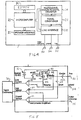
- the measurement circuit for determining the location of a resistive fault is illustrated schematically in Figure 3 connected to a conductor 10 faulted to ground by resistive fault 12.
- the ends of the conductor are designated "a" and "b". In the following, those letters will be used to designate characteristics of the measurement circuit located at those respective ends.
- the measurement circuit includes two instruments 14a and 14b connected to the ends “a" and “b” respectively of the conductor.
- the instruments include respective power supplies 16a and 16b connected to respective polarity reversing switches SW1a and SW1b.
- the switches are connected to ground points Ga and Gb which are located locally at the ends of the cable.
- the ground resistances of Ga and Gb are RGa and RGb respectively.
- Switches SW1a and SW1b are connected to respective digital current meters DCMa and DCMb which are in turn connected to the associated conductor ends through switches SW2a and SW2b.
- Two digital voltmeters DVMa and DVMb are connected to the respective conductor ends and respective reference grounds Gref.
- the reference grounds are placed outside the voltage gradients of the associated local grounds.
- the measuring current is driven through the ground resistances RGa and RGb. These resistances are generally unknown and may cause significant error.
- the placement of the reference grounds Gref outside the local ground voltage gradients minimizes the voltage drop error of the local ground resistance.
- the voltmeters DVMa and DVMb have respective meter resistances RDVMa and RDVMb.
- Ra the resistance of the conductor from end "a" to the resistive fault
- Rb The resistance of the conductor from end "b” to the resistive fault 12
- Rf The resistance of the fault itself
- the location of the ground fault 12 is carried out as follows:
- Instrument 14a calculates: where Va is the voltage to ground at conductor end "a” and Ira is the current in conductor 10 from end "a" to the location of fault 12.
- Instrument 14b calculates: where V1b is the voltage to ground at end "b" of the conductor 10 and llb is the leakage current through volt meter DVMb.
- Instrument 14b calculates: where Vb is the voltage to ground at conductor end "b” and lrb is the current in conductor 10 from end "b" to the location of fault 12.
- Instrument 14a calculates: where V1a is the voltage to ground at end "a" of the conductor 10 and IIa is the leakage current through volt meter DVMa.
- each of the instruments 14a and 14b consists of a microprocessor controlled with firmware instructions stored in EEPROM.
- the microprocessor 20 has an operator interface 22. It is connected to a multi-channel analog to digital converter 24, a signal additioner 26 and a line interface 28.
- the EEPROM 30 operates the test sequence and displays the data results. External connections are a conductor connection 32, a local ground connection 34 and the reference ground connection 36.
- FIG. 5 is a schematic representation of the line interface component of an instrument 14a or 14b.
- the line interface includes the power supply 16 which is connected through an on-off switch 38 to the polarity reversing switch SW1.
- the reversing switch is a double pull-double throw switch with one throw 42 connected to the negative terminal of the power supply through the on-off switch 38.
- the throw 42 connects with either terminal 44 or terminal 46.
- the other throw 48 is connected to the positive terminal of the power supply 16 and connects with either terminal 50 or 52 of the switch.
- the terminals 44 and 52 are connected through enable switch SW2 to the conductor connector 32 of the instrument.
- the terminals 46 and 52 are connected, through a resistor 56 to the ground terminal 34 of the unit.
- An amplifier 58 is connected in parallel across the resistor 56 and serves to provide a signal representing the current in the circuit between the conductor and ground terminals 32 and 34.
- a line voltage amplifier 60 is connected to the upstream side of the enable switch SW2 and to the reference ground terminal 36 to produce a signal representing the voltage between the conductor terminal 32 and the ground reference terminal 36. This equates to the voltage Va discussed above.
- a further amplifier 62 is connected between the ground terminal 34 and the ground reference terminal 36 and generates a signal representing the voltage between these two terminals. The outputs from the three amplifiers are passed to the signal conditioner 26 of the instrument 14.
- a shunt switch 64 is connected across the conductor and ground terminals 32 and 34.
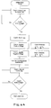
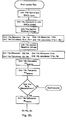
- the flow chart Figures 6a, 6b and 6c describes the method used in fault location. Initially, the two instruments 14a and 14b are connected to the ends of the fault conductor. The two units establish communication over the faulted conductor. Instrument 14b then shorts the line with shunt switch 64. Instrument 14a applies a positive voltage to the conductor and a series of voltage and current readings are taken at end "a" of the conductor. The polarity is then reversed and another series of voltage and current readings are taken at end a. The voltage and current readings are summed and the total line resistance of the conductor is calculated.
- instrument 14a communicates with instrument 14b and initiates a fault location test according to the procedure discussed above.
- the information transmitted is not the raw data but a calculated value, thus minimizing the amount of information that must be transmitted over the faulted conductor.
Landscapes
- Physics & Mathematics (AREA)
- General Physics & Mathematics (AREA)
- Locating Faults (AREA)
Abstract
Description
- The present invention relates to the location of resistive faults in communication and power cables.
- Communication and power cables, which operate exposed to the environment, often develop faults between the insulated conductors or between the metallic shields or armor and earth. Locating and repairing damage to communication and power cables presents a particular challenge when certain types of fault develop. A conductor to conductor or conductor to ground fault caused by moisture is particularly difficult to locate. This type of fault tends to be erratic, with the ohmic value of the fault resistance changing with applied voltage and polarity over time. The unpredictable and electrically noisy nature of such faults makes fault locating using simple loop measurements from the ends of the faulted conductor(s) ineffective.
- A known method of locating a resistive fault between first and second ends of an electric conductor comprises:
- (a) applying a DC voltage to the first end of the conductor;
- (b) taking a series of first voltage readings of the DC voltage at the first end of the conductor;
- (c) taking a series of first current readings at the first end of the conductor;
- (d) taking a series of second voltage readings of the DC voltage at the second end of the conductor;
- (e) recording the first voltage, first current and second voltage readings;
- (f) computing from the first voltage, first current and second voltage readings the resistance of the conductor between the resistive fault and the first end of the conductor; and
- (g) computing the distance between the resistive fault and the first end of the conductor from the computed resistance of the conductor.
- A known apparatus for locating a resistive fault between first and second ends of an electric conductor comprises:
- a first power supply for applying a DC voltage to the first end of the conductor;
- first voltage metering means for taking a series of first voltage readings of the DC voltage at the first end of the conductor;
- first current metering means for taking a series of first current readings at the first end of the conductor;
- second voltage metering means for taking a series of second voltage readings of the DC voltage at the second end of the conductor;
- recording means for recording the first voltage, first current and second voltage readings;
- means for computing from the first voltage, first current and second voltage readings the resistance of the conductor between the resistive fault and at least one end of the conductor; and
- means for computing the distance between the resistive fault and at least one end of the conductor from the computed resistance of the conductor.
- A measurement method and of this type are described by Vokey et al in U.S. patent no. 4,947,469. The patent details a method whereby instruments are placed at both ends of the faulted conductor(s). A series of simultaneous measurements are then carried out by carefully synchronizing the instruments such that the voltage and current readings are recorded at both ends at the same instant. The instrument at the remote end transmits its measurement data to the first instrument for computation. The conductor resistances are then calculated as follows:


- Va is the voltage at end a, la is the current at end a;
- Vb is the voltage at end b, lb is the current at end b;
- i is the ith simultaneous measurement; and
- N is the number of simultaneous measurements.
- A fundamental limitation exists in this method. The simultaneous measurement of the voltage and current at the conductor ends assumes that steady state conditions will predictably exist at both ends at the same instant.
- In practical applications such as locating damage to the plastic and steel protective outer jacket on buried fiber optic communication cables, the conductor ends can be 100 km or more apart. At these distances the series resistance and parallel capacitance to ground of the protective steel armor gives rise to transmission line phase delays. Disturbances along the conductor from external electrical influences such as power lines or telluric earth currents affect the ends of the conductors differently at different times. These disturbances coupled with time delays result in different transient voltage and current conditions at different times at the conductor ends. These transient voltages can introduce measurement errors at the precise time of the simultaneous measurements.
- The present invention is concerned with a determination of the distance to a conductor fault without the inherent susceptibility to errors caused by transient voltages and other electrical disturbances.
- According to one aspect of the present invention there is provided a method of the above type that is characterized by:
- (h) taking the readings without synchronizing the taking of readings at the first and second ends of the conductor;
- (i) analyzing the readings and discarding readings analyzed to have been effected by transients;
- (j) computing from the undiscarded readings average values for the first voltage, first current and second voltage readings; and
- (k) computing from the average values for the first voltage, first current and second voltage readings the resistance of the conductor between the resistive fault and the first end of the conductor.
- The invention thus calculates the distance to a resistive fault from a series of measurements which are made independently at both ends of the faulted conductor. During a measurement cycle, the instruments connected to the conductor ends take a series of voltage and current readings. At the end of the cycle the data is examined for transient conditions. The transient data is statistically eliminated ensuring that steady state readings only are used for the calculation, thereby eliminating errors from electrical disturbances. The average of the remaining data is then calculated and saved.
- No attempt is made to synchronize the measurements. The instruments make independent and therefore uncorrelated measurements during the test cycle. Another significant advantage exists in that the time to establish the synchronized communication and measurement routine is eliminated. The remote unit preferably processes the data independently, so that the remote unit only needs to transmit the computed average values back to the controlling end rather than every single data point. This greatly speeds up the measurement routine and produces more accurate results in a fraction of the time.
- In preferred embodiments of the invention, the process is repeated applying positive and negative DC voltages to the conductor and the complete measurement cycle is completed from the second end of the conductor.
- According to another aspect of the present invention there is provided an apparatus of the above type characterized by:
- means for analyzing the readings and discarding readings analyzed to have been effected by transients;
- means for computing from the undiscarded readings average values for the first voltage, first current and second voltage readings; and
- means for computing from the average values for the first voltage, first current and second voltage readings the resistance of the conductor between the resistive fault and at least one end of the conductor.
- The apparatus is preferably two similar control units connected to opposite ends of the faulted conductor. Each unit has a computing capability to analyze the readings taken and to compute average values to be communicated between the units.
- In the accompanying drawings, which illustrate an exemplary embodiment of the present invention:
- Figure 1 is a chart showing the transient voltage conditions at the end of a long conductor;
- Figure 2 is a chart like Figure 1 showing a typical test cycle;
- Figure 3 is a schematic view of the measurement circuit according to the present invention;
- Figure 4 is a schematic of a control unit;
- Figure 5 is a schematic line interface included in the control unit; and
- Figures 6a through 6d are a flow chart describing the operation of the apparatus.
- In practical applications of the present invention, such as locating damage to the plastic and steel protective outer jacket on buried fibre optic communication cables, the conductor ends can be 100 km or more apart. At these distances, the series resistance and parallel capacitance to ground of the protective steel armor gives rise to transmission line phase delays. Disturbances along the conductor from external electrical influences such as power lines or telluric earth currents affect the ends of the conductors differently at different times. These disturbances, coupled with time delays result in different transient voltage and current conditions at different times at the conductor ends. This is shown graphically in Figure 1. As shown in that figure a simultaneous measurement of voltage at opposite ends of the conductor ends "a" and "b" can introduce measurement errors at the precise time of the simultaneous measurements.
- As shown in Figure 2, with the present invention there is no attempt made to synchronize the measurements. The independent and therefore uncorrelated measurements are made at opposite ends of the conductor during a measurement cycle. The data produced is analyzed and data analyzed as being affected by transients is discarded. The remaining, saved data is representative of steady state conditions.
- The measurement circuit for determining the location of a resistive fault is illustrated schematically in Figure 3 connected to a
conductor 10 faulted to ground byresistive fault 12. The ends of the conductor are designated "a" and "b". In the following, those letters will be used to designate characteristics of the measurement circuit located at those respective ends. - The measurement circuit includes two
instruments - Two digital voltmeters DVMa and DVMb are connected to the respective conductor ends and respective reference grounds Gref. The reference grounds are placed outside the voltage gradients of the associated local grounds.
- The measuring current is driven through the ground resistances RGa and RGb. These resistances are generally unknown and may cause significant error. The placement of the reference grounds Gref outside the local ground voltage gradients minimizes the voltage drop error of the local ground resistance.
- The voltmeters DVMa and DVMb have respective meter resistances RDVMa and RDVMb. As shown in Figure 3, the resistance of the conductor from end "a" to the resistive fault is designated Ra. The resistance of the conductor from end "b" to the
resistive fault 12 is designated Rb. The resistance of the fault itself is designated Rf. - The location of the
ground fault 12 is carried out as follows: - 1. Switch SW2b is open to disconnect power supply 16b. Switch SW2a is closed to connect the power supply 16a to the
conductor 10. The power supply switch SW1a is set to make the conductor positive with respect to ground. - 2. The voltmeters DVMa and DVMb and current meter DCMa independently take a series of reading over a measurement cycle.
- 3. At the end of the measurement cycle, the test voltage is removed and the instruments independently analyze the readings. Those readings analyzed as affected by transient conditions are discarded and the remaining readings are averaged. The technique used for identifying readings as affected by transient conditions involve calculating the mean of the readings:


- The measurements Xi that are within the bounds


- 4. At end "a" the
instrument 14a retains N reading Vai + and lai + .Instrument 14b retains M readings of V1bi + . - 5. The power supply switch SW1a is thrown to make the conductor negative with respect to ground and steps 2, 3 and 4 are repeated.
Instrument 14a retains N readings of Vai- and lai-.Instrument 14b retains M readings of V1bi-. - 6. The instruments compute the averages of the recorded readings.
-
Instrument 14a calculates:
conductor 10 from end "a" to the location offault 12. -
Instrument 14b calculates:
conductor 10 and llb is the leakage current through volt meter DVMb. - The conductor resistance Ra from the end "a" to the ground fault and the conductor voltage to ground at the ground fault R approximated using the following formulas:

V1bi ≈ Vf1i; V1bi = Voltage Measurements at "b"
llbi =
RDVMb = Known Impedance at DVMb (Ideal DVM resistance = ∞),
lrai = lai - llai -
Vai = Voltage measurement at "a"
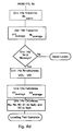
RDVMa = Known Impedance at DVMa (Ideal DVM resistance = ∞ - 7. Switch SW2a is opened to disconnect the power supply 16a. Switch SW2b is closed to connected power supply 16b. The power supply switch SW1b is set to make the conductor positive with respect to ground.
- 8. The voltmeters DVMa and DVMb and current meter DCMb independently take a series of readings over a measurement cycle.
- 9. At the end of the measurement cycle the test voltage is removed and the instruments independently analyze the readings taken. Those readings analyzed as affected by transient conditions are discarded and remaining readings are averaged.
- 10. At end "b" the
instrument 14b retains N readings Vbi + and lbi +.Instrument 14a retains M readings of V1 ai +. - 11. The power supply switch SW1b is thrown to make the conductor negative with respect to ground and steps 8 and 9 are repeated.
Instrument 14b retains N readings of Vbi- and lbi-.Instrument 14a retains M readings of V1ai-. - 12. The instruments compute the averages of the recorded readings.
-
Instrument 14b calculates:
conductor 10 from end "b" to the location offault 12. -
Instrument 14a calculates:
conductor 10 and IIa is the leakage current through volt meter DVMa. - The conductor resistance Rb from the end "b" to the ground fault and the conductor voltage to ground at the ground fault are approximated using the following formulas:

V1ai ≈ Vf2i; V1ai = Voltage Measurements at "a"
llai =
RDVMa = Known Impedance at DVMa (Ideal DVM resistance = ∞),
Irbi = Ibi - llbi -
Vbi = Voltage measurement at "b"
RDVMb = Known Impedance at DVMb (Ideal DVM resistance = ∞) - 13.
Instrument 14a, which has calculated the approximate values for conductor resistances Ra and Rb, transmits the approximation of resistance Rb toinstrument 14b. This allows the values to be refined by eliminating leakage currents. - 14. The correct values of Ra, Rb and Rf, the fault resistance, are then calculated by eliminating the error produced by the voltage drops across the volt meters caused by the leakage currents through the volt meters.
- 15. The conductor resistance Ra and fault resistance Rf1 are calculated as follows:

- RDVMb = DVM impedance at "b"
- V1bi = Voltage measurement at "b" when SW2b opened
- lrai = lai-llai = lai -

- Vai = Voltage measurements at "a" when SW2a closed
- llbi =

- V1bi = Voltage measurement at "b" when SW2b opened
- lf1 =


- 16. The conductor resistance Rb from end "b" to the fault and the fault resistance Rf2 are calculated as followed:

- RDVMa = Known DVM impedance at "a"
- V1ai = Voltage measurements at "a" when SW2a opened
- lrbi = lbi - llbi = lbi -

- Vbi = Voltage measurements at "b" when SW2b closed
- RDVMb = Known DVM impedance at "b"
- llai =

- V1ai = Voltage measurement at "b" when SW2b opened
- If2 =


- Referring to Figure 4, each of the
instruments microprocessor 20 has anoperator interface 22. It is connected to a multi-channel analog todigital converter 24, asignal additioner 26 and aline interface 28. The EEPROM 30 operates the test sequence and displays the data results. External connections are aconductor connection 32, alocal ground connection 34 and thereference ground connection 36. - Figure 5 is a schematic representation of the line interface component of an
instrument power supply 16 which is connected through an on-off switch 38 to the polarity reversing switch SW1. The reversing switch is a double pull-double throw switch with one throw 42 connected to the negative terminal of the power supply through the on-off switch 38. The throw 42 connects with either terminal 44 orterminal 46. Theother throw 48 is connected to the positive terminal of thepower supply 16 and connects with either terminal 50 or 52 of the switch. Theterminals conductor connector 32 of the instrument. Theterminals resistor 56 to theground terminal 34 of the unit. Thus, with the enable switch closed and terminals 51 and 55 engaged, theconductor terminal 32 is at a negative potential with respect to theground terminal 34. With theswitch terminals conductor terminal 32 is positive with respect to theground terminal 34. - An amplifier 58 is connected in parallel across the
resistor 56 and serves to provide a signal representing the current in the circuit between the conductor andground terminals line voltage amplifier 60 is connected to the upstream side of the enable switch SW2 and to thereference ground terminal 36 to produce a signal representing the voltage between theconductor terminal 32 and theground reference terminal 36. This equates to the voltage Va discussed above. Afurther amplifier 62 is connected between theground terminal 34 and theground reference terminal 36 and generates a signal representing the voltage between these two terminals. The outputs from the three amplifiers are passed to thesignal conditioner 26 of the instrument 14. - A
shunt switch 64 is connected across the conductor andground terminals - The flow chart Figures 6a, 6b and 6c describes the method used in fault location. Initially, the two
instruments Instrument 14b then shorts the line withshunt switch 64.Instrument 14a applies a positive voltage to the conductor and a series of voltage and current readings are taken at end "a" of the conductor. The polarity is then reversed and another series of voltage and current readings are taken at end a. The voltage and current readings are summed and the total line resistance of the conductor is calculated. - After the line resistance test,
instrument 14a communicates withinstrument 14b and initiates a fault location test according to the procedure discussed above. At each occasion during the process when one of the instruments transmits a signal to the other, the information transmitted is not the raw data but a calculated value, thus minimizing the amount of information that must be transmitted over the faulted conductor. - While one particular embodiment of the present invention has been described in the foregoing, it is to be understood that other embodiments are possible within the scope of the invention and are intended to be included herein. The invention is to be considered limited solely by the scope of the appended claims.
Claims (8)
- A method of locating a resistive fault between first and second ends of an electric conductor, said method comprising:(a) applying a DC voltage to the first end of the conductor;(b) taking a series of first voltage readings of the DC voltage at the first end of the conductor;(c) taking a series of first current readings at the first end of the conductor;(d) taking a series of second voltage readings of the DC voltage at the second end of the conductor;(e) recording the first voltage, first current and second voltage readings; (f) computing from the first voltage, first current and second voltage readings the resistance of the conductor between the resistive fault and the first end of the conductor; and(g) computing the distance between the resistive fault and the first end of the conductor from the computed resistance of the conductor, CHARACTERIZED BY:(h) taking the readings without synchronizing the taking of readings at the first and second ends of the conductor;(i) analyzing the readings and discarding readings analyzed to have been effected by transients;(j) computing from the undiscarded readings average values for the first voltage, first current and second voltage readings; and(k) computing from the average values for the first voltage, first current and second voltage readings the resistance of the conductor between the resistive fault and the first end of the conductor.
- A method according to Claim 1 comprising the further steps of:(I) applying a DC voltage to the second end of the conductor;(m) taking a series of third voltage readings of the DC voltage at the second end of the conductor;(n) taking a series of second current readings at the second end of the conductor;(o) taking a series of fourth voltage readings of the DC voltage at the first end of the conductor;(p) recording the third voltage, second current and fourth voltage readings;FURTHER CHARACTERIZED BY:(q) taking the third voltage, second current and fourth voltage readings without synchronizing the taking of readings at the first and second ends of the conductor;(r) analyzing the readings and discarding readings analyzed to have been effected by transients;(s) computing from the undiscarded readings average values for the third voltage, second current and fourth voltage readings;(t) computing from the average values for the third voltage, second current and fourth voltage readings the resistance of the conductor between the resistive fault and the second end of the conductor; and(u) computing the distance between the resistive fault and the second end of the conductor from the computed resistance of the conductor.
- A method according to Claim 1 comprising performing steps (a) through (e) twice, with applied DC voltages of opposite polarity.
- A method according to Claim 2 comprising performing steps (a) through (e) twice, with applied DC voltages of opposite polarity, and performing steps (I) through (p) twice, with applied DC voltages of opposite polarity.
- An apparatus for locating a resistive fault (12) between first and second ends (a; b) of an electric conductor (10), said apparatus comprising:a first power supply (16a) for applying a DC voltage to the first end (a) of the conductor;first voltage metering means (DVMa) for taking a series of first voltage readings of the DC voltage at the first end of the conductor;first current metering means (DCMa) for taking a series of first current readings at the first end of the conductor;second voltage metering means (DVMb) for taking a series of second voltage readings of the DC voltage at the second end of the conductor;recording means for recording the first voltage, first current and second voltage readings;means for computing from the first voltage, first current and second voltage readings the resistance of the conductor between the resistive fault and at least one end of the conductor; andmeans for computing the distance between the resistive fault and at least one end of the conductor from the computed resistance of the conductor,CHARACTERIZED BY:means for analyzing the readings and discarding readings analyzed to have been effected by transients;means for computing from the undiscarded readings average values for the first voltage, first current and second voltage readings; andmeans for computing from the average values for the first voltage, first current and second voltage readings the resistance of the conductor between the resistive fault and at least one end of the conductor.
- An apparatus according to Claim 5 wherein the apparatus includes:a second power supply (14b) for applying a DC voltage to the second end of the conductor;switch means (SW2a; SW2b) for selectively connecting and disconnecting the first and second power supplies to the conductor; andsecond current metering means (DCMb) for taking a series of second current readings at the second end of the conductor.
- An apparatus according to Claim 6 wherein each power supply includes polarity reversing switch means (SW1a; SW1b) for applying DC voltages of opposite polarities to the ends of the conductor.
- An apparatus according to Claim 6 or 7 comprising first and second control units (14a; 14b) for connection to the first and second ends of the conductor, each control unit including:a respective one of the voltage metering means (DVMa; DVMb);a respective one of the current metering means(DCMa; DCMb);recording means for recording the respective voltage and current readings;means for analyzing the respective voltage and current readings and discarding readings analyzed to have been effected by transients;means for computing from the undiscarded readings average values for the respective voltage and current readings;means for transmitting computed average values to the other unit over the conductor; andmeans for receiving computed average values from the other unit.
Applications Claiming Priority (2)
| Application Number | Priority Date | Filing Date | Title |
|---|---|---|---|
| CA 2179249 CA2179249C (en) | 1996-06-17 | 1996-06-17 | Resistive fault location |
| CA2179249 | 1996-06-17 |
Publications (2)
| Publication Number | Publication Date |
|---|---|
| EP0819947A2 true EP0819947A2 (en) | 1998-01-21 |
| EP0819947A3 EP0819947A3 (en) | 1998-12-02 |
Family
ID=4158418
Family Applications (1)
| Application Number | Title | Priority Date | Filing Date |
|---|---|---|---|
| EP97304252A Withdrawn EP0819947A3 (en) | 1996-06-17 | 1997-06-17 | Resistive fault location |
Country Status (2)
| Country | Link |
|---|---|
| EP (1) | EP0819947A3 (en) |
| CA (1) | CA2179249C (en) |
Cited By (4)
| Publication number | Priority date | Publication date | Assignee | Title |
|---|---|---|---|---|
| EP0964256A1 (en) * | 1998-06-10 | 1999-12-15 | Automobiles Peugeot | Method and device for locating short circuits in a bus of a multiplexed network for information transmission |
| WO2003044547A1 (en) * | 2001-11-23 | 2003-05-30 | Abb Ab | Fault location using measurements from two ends of a line |
| US6590962B1 (en) * | 2000-06-21 | 2003-07-08 | Teradyne, Inc. | Method of performing non-interactive resistive fault location |
| WO2018200817A1 (en) * | 2017-04-26 | 2018-11-01 | VoltServer, Inc. | Methods for verifying digital-electricity line integrity |
Citations (3)
| Publication number | Priority date | Publication date | Assignee | Title |
|---|---|---|---|---|
| JPS62134571A (en) * | 1985-12-09 | 1987-06-17 | Fuji Electric Co Ltd | System for locating troubled point |
| EP0327191A2 (en) * | 1988-01-05 | 1989-08-09 | Automated Light Technologies | Resistive fault location means and device for use on electrical cables |
| US5455776A (en) * | 1993-09-08 | 1995-10-03 | Abb Power T & D Company Inc. | Automatic fault location system |
-
1996
- 1996-06-17 CA CA 2179249 patent/CA2179249C/en not_active Expired - Lifetime
-
1997
- 1997-06-17 EP EP97304252A patent/EP0819947A3/en not_active Withdrawn
Patent Citations (3)
| Publication number | Priority date | Publication date | Assignee | Title |
|---|---|---|---|---|
| JPS62134571A (en) * | 1985-12-09 | 1987-06-17 | Fuji Electric Co Ltd | System for locating troubled point |
| EP0327191A2 (en) * | 1988-01-05 | 1989-08-09 | Automated Light Technologies | Resistive fault location means and device for use on electrical cables |
| US5455776A (en) * | 1993-09-08 | 1995-10-03 | Abb Power T & D Company Inc. | Automatic fault location system |
Non-Patent Citations (1)
| Title |
|---|
| PATENT ABSTRACTS OF JAPAN vol. 011, no. 358 (P-639), 21 November 1987 (1987-11-21) & JP 62 134571 A (FUJI ELECTRIC CO LTD;OTHERS: 01), 17 June 1987 (1987-06-17) * |
Cited By (8)
| Publication number | Priority date | Publication date | Assignee | Title |
|---|---|---|---|---|
| EP0964256A1 (en) * | 1998-06-10 | 1999-12-15 | Automobiles Peugeot | Method and device for locating short circuits in a bus of a multiplexed network for information transmission |
| FR2779828A1 (en) * | 1998-06-10 | 1999-12-17 | Peugeot | PROCESS FOR LOCATING SHORT-CIRCUITS IN AT LEAST ONE BUS OF A MULTIPLEX INFORMATION TRANSMISSION NETWORK AND DIAGNOSIS DEVICE IMPLEMENTING THE PROCEDURE |
| US6590962B1 (en) * | 2000-06-21 | 2003-07-08 | Teradyne, Inc. | Method of performing non-interactive resistive fault location |
| WO2003044547A1 (en) * | 2001-11-23 | 2003-05-30 | Abb Ab | Fault location using measurements from two ends of a line |
| US7221166B2 (en) | 2001-11-23 | 2007-05-22 | Abb Ab | Fault location using measurements from two ends of a line |
| WO2018200817A1 (en) * | 2017-04-26 | 2018-11-01 | VoltServer, Inc. | Methods for verifying digital-electricity line integrity |
| IL270145B1 (en) * | 2017-04-26 | 2023-08-01 | Voltserver Inc | Methods for verifying digital-electricity line integrity |
| US11892494B2 (en) | 2017-04-26 | 2024-02-06 | VoltServer, Inc. | Methods for verifying digital-electricity line integrity |
Also Published As
| Publication number | Publication date |
|---|---|
| CA2179249A1 (en) | 1997-12-18 |
| EP0819947A3 (en) | 1998-12-02 |
| CA2179249C (en) | 2000-11-14 |
Similar Documents
| Publication | Publication Date | Title |
|---|---|---|
| US5990686A (en) | Method and apparatus for locating resistive faults in communication and power cables | |
| EP0327191B1 (en) | Resistive fault location means and device for use on electrical cables | |
| AU766993B2 (en) | Method and device for locating an insulation fault in an electric cable | |
| US5481198A (en) | Method and device for measuring corrosion on a portion of a metallic path carrying an undetermined load current | |
| US20060097728A1 (en) | Fault location using measurements of current and voltage from one end of a line | |
| JPH0242196B2 (en) | ||
| US7323880B2 (en) | Ground circuit impedance measurement | |
| EP0936469B1 (en) | Loop resistance tester (LRT) for cable shield integrity monitoring | |
| EP0819947A2 (en) | Resistive fault location | |
| US7710122B2 (en) | Ground resistance test apparatus | |
| US4276619A (en) | Impedance and common mode rejection testing of a multi-channel seismic data gathering apparatus | |
| EP0718949A1 (en) | Protective relay system with spacial difference filter and summing filter | |
| US7068040B2 (en) | Ground circuit impedance measurement apparatus and method | |
| US4839598A (en) | Method for testing underground electric cables | |
| EP0206161A2 (en) | Automatic telephone line fault locator | |
| US6825653B2 (en) | Load compensating power supply having minimally invasive device current analyzer | |
| CN213398688U (en) | Multifunctional tester and testing system | |
| EP0285320B1 (en) | Apparatus and method for determining the values of circuit elements in a three terminal equivalent circuit | |
| EP0155367B1 (en) | Short-circuit distance relay | |
| WO1990011533A2 (en) | Detecting cable faults | |
| EP0570654A1 (en) | A remote eart resistance meter | |
| US20020012540A1 (en) | Method of fault location in parallel lines with series compensation | |
| EP0969286A2 (en) | An apparatus for the determination of electrical power and a method of testing or calibrating a plurality of such apparatus | |
| Orságová | Ripple control signal using for earth fault location in MV networks | |
| JPH063402A (en) | Fault locator |
Legal Events
| Date | Code | Title | Description |
|---|---|---|---|
| PUAI | Public reference made under article 153(3) epc to a published international application that has entered the european phase |
Free format text: ORIGINAL CODE: 0009012 |
|
| AK | Designated contracting states |
Kind code of ref document: A2 Designated state(s): DE FR GB IT |
|
| RIN1 | Information on inventor provided before grant (corrected) |
Inventor name: AMINOT, GILLES Inventor name: SONTAG, KENNETH N. Inventor name: VOKEY, DAVID E. |
|
| PUAL | Search report despatched |
Free format text: ORIGINAL CODE: 0009013 |
|
| AK | Designated contracting states |
Kind code of ref document: A3 Designated state(s): AT BE CH DE DK ES FI FR GB GR IE IT LI LU MC NL PT SE |
|
| 17P | Request for examination filed |
Effective date: 19990510 |
|
| AKX | Designation fees paid |
Free format text: DE FR GB IT |
|
| GRAP | Despatch of communication of intention to grant a patent |
Free format text: ORIGINAL CODE: EPIDOSNIGR1 |
|
| STAA | Information on the status of an ep patent application or granted ep patent |
Free format text: STATUS: THE APPLICATION IS DEEMED TO BE WITHDRAWN |
|
| 18D | Application deemed to be withdrawn |
Effective date: 20050226 |