EP0819925A2 - A preignition detection apparatus - Google Patents
A preignition detection apparatus Download PDFInfo
- Publication number
- EP0819925A2 EP0819925A2 EP97401555A EP97401555A EP0819925A2 EP 0819925 A2 EP0819925 A2 EP 0819925A2 EP 97401555 A EP97401555 A EP 97401555A EP 97401555 A EP97401555 A EP 97401555A EP 0819925 A2 EP0819925 A2 EP 0819925A2
- Authority
- EP
- European Patent Office
- Prior art keywords
- preignition
- vibration
- detecting
- abnormal
- abnormal vibration
- Prior art date
- Legal status (The legal status is an assumption and is not a legal conclusion. Google has not performed a legal analysis and makes no representation as to the accuracy of the status listed.)
- Granted
Links
- 238000001514 detection method Methods 0.000 title abstract description 14
- 230000002159 abnormal effect Effects 0.000 claims abstract description 125
- 238000002485 combustion reaction Methods 0.000 claims description 13
- 238000000034 method Methods 0.000 claims description 10
- 230000001186 cumulative effect Effects 0.000 abstract description 4
- 230000004043 responsiveness Effects 0.000 abstract 1
- 239000000446 fuel Substances 0.000 description 24
- 238000010586 diagram Methods 0.000 description 10
- 239000000203 mixture Substances 0.000 description 5
- 238000010276 construction Methods 0.000 description 4
- 230000006870 function Effects 0.000 description 3
- 150000002500 ions Chemical class 0.000 description 3
- 230000000670 limiting effect Effects 0.000 description 3
- 230000007423 decrease Effects 0.000 description 2
- 230000003111 delayed effect Effects 0.000 description 2
- 238000013459 approach Methods 0.000 description 1
- 230000006835 compression Effects 0.000 description 1
- 238000007906 compression Methods 0.000 description 1
- 230000003247 decreasing effect Effects 0.000 description 1
- 230000002708 enhancing effect Effects 0.000 description 1
- 230000007613 environmental effect Effects 0.000 description 1
- 238000010304 firing Methods 0.000 description 1
- 230000002401 inhibitory effect Effects 0.000 description 1
- 238000012544 monitoring process Methods 0.000 description 1
- TVMXDCGIABBOFY-UHFFFAOYSA-N octane Chemical compound CCCCCCCC TVMXDCGIABBOFY-UHFFFAOYSA-N 0.000 description 1
- 238000000746 purification Methods 0.000 description 1
- 230000002829 reductive effect Effects 0.000 description 1
- 230000000979 retarding effect Effects 0.000 description 1
Images




Classifications
-
- G—PHYSICS
- G01—MEASURING; TESTING
- G01L—MEASURING FORCE, STRESS, TORQUE, WORK, MECHANICAL POWER, MECHANICAL EFFICIENCY, OR FLUID PRESSURE
- G01L23/00—Devices or apparatus for measuring or indicating or recording rapid changes, such as oscillations, in the pressure of steam, gas, or liquid; Indicators for determining work or energy of steam, internal-combustion, or other fluid-pressure engines from the condition of the working fluid
- G01L23/22—Devices or apparatus for measuring or indicating or recording rapid changes, such as oscillations, in the pressure of steam, gas, or liquid; Indicators for determining work or energy of steam, internal-combustion, or other fluid-pressure engines from the condition of the working fluid for detecting or indicating knocks in internal-combustion engines; Units comprising pressure-sensitive members combined with ignitors for firing internal-combustion engines
- G01L23/221—Devices or apparatus for measuring or indicating or recording rapid changes, such as oscillations, in the pressure of steam, gas, or liquid; Indicators for determining work or energy of steam, internal-combustion, or other fluid-pressure engines from the condition of the working fluid for detecting or indicating knocks in internal-combustion engines; Units comprising pressure-sensitive members combined with ignitors for firing internal-combustion engines for detecting or indicating knocks in internal combustion engines
- G01L23/225—Devices or apparatus for measuring or indicating or recording rapid changes, such as oscillations, in the pressure of steam, gas, or liquid; Indicators for determining work or energy of steam, internal-combustion, or other fluid-pressure engines from the condition of the working fluid for detecting or indicating knocks in internal-combustion engines; Units comprising pressure-sensitive members combined with ignitors for firing internal-combustion engines for detecting or indicating knocks in internal combustion engines circuit arrangements therefor
-
- F—MECHANICAL ENGINEERING; LIGHTING; HEATING; WEAPONS; BLASTING
- F02—COMBUSTION ENGINES; HOT-GAS OR COMBUSTION-PRODUCT ENGINE PLANTS
- F02D—CONTROLLING COMBUSTION ENGINES
- F02D35/00—Controlling engines, dependent on conditions exterior or interior to engines, not otherwise provided for
- F02D35/02—Controlling engines, dependent on conditions exterior or interior to engines, not otherwise provided for on interior conditions
- F02D35/027—Controlling engines, dependent on conditions exterior or interior to engines, not otherwise provided for on interior conditions using knock sensors
-
- G—PHYSICS
- G01—MEASURING; TESTING
- G01L—MEASURING FORCE, STRESS, TORQUE, WORK, MECHANICAL POWER, MECHANICAL EFFICIENCY, OR FLUID PRESSURE
- G01L23/00—Devices or apparatus for measuring or indicating or recording rapid changes, such as oscillations, in the pressure of steam, gas, or liquid; Indicators for determining work or energy of steam, internal-combustion, or other fluid-pressure engines from the condition of the working fluid
- G01L23/22—Devices or apparatus for measuring or indicating or recording rapid changes, such as oscillations, in the pressure of steam, gas, or liquid; Indicators for determining work or energy of steam, internal-combustion, or other fluid-pressure engines from the condition of the working fluid for detecting or indicating knocks in internal-combustion engines; Units comprising pressure-sensitive members combined with ignitors for firing internal-combustion engines
- G01L23/221—Devices or apparatus for measuring or indicating or recording rapid changes, such as oscillations, in the pressure of steam, gas, or liquid; Indicators for determining work or energy of steam, internal-combustion, or other fluid-pressure engines from the condition of the working fluid for detecting or indicating knocks in internal-combustion engines; Units comprising pressure-sensitive members combined with ignitors for firing internal-combustion engines for detecting or indicating knocks in internal combustion engines
-
- G—PHYSICS
- G01—MEASURING; TESTING
- G01M—TESTING STATIC OR DYNAMIC BALANCE OF MACHINES OR STRUCTURES; TESTING OF STRUCTURES OR APPARATUS, NOT OTHERWISE PROVIDED FOR
- G01M15/00—Testing of engines
- G01M15/04—Testing internal-combustion engines
- G01M15/12—Testing internal-combustion engines by monitoring vibrations
-
- F—MECHANICAL ENGINEERING; LIGHTING; HEATING; WEAPONS; BLASTING
- F02—COMBUSTION ENGINES; HOT-GAS OR COMBUSTION-PRODUCT ENGINE PLANTS
- F02D—CONTROLLING COMBUSTION ENGINES
- F02D41/00—Electrical control of supply of combustible mixture or its constituents
- F02D41/22—Safety or indicating devices for abnormal conditions
Definitions
- the present invention relates to a preignition detection apparatus for an internal combustion engine, and more particularly to a preignition detection apparatus capable of detecting a preignition condition in an incipient stage.
- Preignition is defined as the phenomenon that an air-fuel mixture is spontaneously ignited during the compression stroke by residual heat contained in deposits which adhere to the ignition plug and/or an inner wall of an engine cylinder.
- Preignition causes not only a sharp decrease of the output of an engine and/or a fluctuation of engine speed, but can also damage the engine, at the worst.
- the above-mentioned engine control device cannot prevent the engine being damaged, because it determines that preignition has occurred when abnormal engine vibration, the magnitude thereof being greater than a predetermined level, is detected and cannot determine that preignition has occurred until after preignition has become significantly serious.
- a preignition detecting apparatus comprises: a vibration detecting means for detecting vibration of an internal combustion engine; an abnormal vibration occurrence interval measuring means for measuring a time interval while abnormal vibration higher than a predetermined level is being detected by said vibration detecting means; a frequent vibration continuing interval measuring means for measuring a time interval while the abnormal vibration occurrence interval measured by said abnormal vibration occurrence interval measuring means is shorter than a predetermined non-abnormal vibration continuing interval; and a preignition determining means for determining that preignition has occurred when the frequent vibration continuing internal measured by said frequent vibration continuing internal measuring means becomes longer than a predetermined preignition determining interval.
- this preignition detecting apparatus it is determined that preignition has occurred when a frequent vibration continuing interval becomes longer than a predetermined interval.
- a preignition detecting apparatus comprises: a vibration detecting means for detecting vibration of an internal combustion engine; an abnormal vibration occurrence frequency calculating means for calculating a frequency in detecting of abnormal vibration higher than a predetermined level by said vibration detecting means; an accumulating means for accumulating the frequency calculated by said abnormal vibration occurrence frequency calculating means; and a preignition determining means for determining that preignition has occurred when the accumulated frequency becomes larger than a predetermined preignition determining value.
- this preignition detecting apparatus it is determined that preignition has occurred when an accumulated frequency becomes larger than a predetermined value.
- FIG. 1 is a diagram showing the configuration of a preignition detection apparatus according to the present invention.
- An internal combustion engine 10 has a piston 103 which moves up and down in a cylinder 102 bored in a cylinder block 101.
- An intake valve 104, an exhaust valve 105, and a spark plug 106 are mounted on the top of the cylinder 102, an air/fuel mixture, drawn through the intake valve 104 and compressed by the upward movement of the piston 103, is ignited by the spark plug 106 and is caused to expand, forcing the piston 103 downward and thus generating power.
- the up and down motion of the piston is converted to rotary motion by means of a crankshaft (not shown).
- a timing rotor 107 is attached to the forward end of the crankshaft.
- the timing rotor 107 has a total of 12 teeth formed at intervals of 30°, and as each tooth of the timing rotor 107 passes, a pulse is outputted from a crankshaft position sensor 111 mounted in close proximity to the timing rotor 107. In this way, the crankshaft angle can be detected every 30° by means of the crankshaft position sensor 111.
- An intake camshaft (not shown) which drives the intake valve 104 is equipped with a protruding tab, and as the protruding tab passes, a pulse is outputted from a camshaft sensor 112 mounted in close proximity to the intake camshaft. In this way, one revolution of the camshaft, i.e., one cycle of the internal combustion engine, can be detected by means of the camshaft sensor 112.
- a vibration sensor 113 is mounted in the cylinder block 101 to detect vibration occurring in the internal combustion engine.
- the controller 12 is constructed from a microcomputer consisting of a CPU 122, a memory 123, an input interface 124, and an output interface 125, which are interconnected by a data bus 121.
- the output of each sensor is fetched into the CPU 122 via the input interface 124.
- the output interface 125 of the controller 12 outputs an ignition command signal which is supplied to the spark plug 106 via an igniter 131 and an ignition coil 132.
- knocking also causes engine vibration and knocking occurs when a residual combustible gas in the cylinder 102 self-ignites after sparking of the spark plug 106.
- preignition does not occur. Accordingly, the detection of preignition is performed in an ignition timing control routine for inhibiting knocking.
- FIG. 2 is a flowchart of the ignition timing control routine executed in the controller 12. This routine is executed every fixed interval.
- step 20 output R of the vibration sensor 113 mounted in the cylinder block 101 is read, and at step 21, a vibration level K is determined as a function of the output R of the vibration sensor 113.
- K K(R)
- the moving average of the output R of the vibration sensor 113 can be used for determining the vibration level.
- step 22 it is determined whether or not the vibration level K is greater than or equal to a predetermined threshold value ⁇ , to determine whether or not the engine is experiencing abnormal vibration.
- an adjustment value ⁇ T ad for adjusting a reference ignition timing TI is decreased by a prescribed advancing amount ⁇ T L at step 23 before proceeding to step 25.
- the adjustment value ⁇ T ad is subtracted from the reference ignition timing TI, thereby advancing or retarding the ignition angle to determine the ignition timing T.
- the reference ignition timing TI is calculated as a function of engine speed Ne and intake air flow rate Qa. TI ⁇ TI(Ne, Qa)
- the value of the prescribed retardation amount ⁇ T D is made larger than the value of the prescribed advancing amount ⁇ T L .
- step 26 the ignition timing T is limited between predetermined most retarded timing T D and the reference ignition timing TI, and the control proceeds to step 27.
- a preignition detecting subroutine is executed, and then the routine is terminated.
- FIG. 3 is a flowchart illustrating the first preignition detecting subroutine executed at step 27.
- step 27A it is determined whether or not the vibration level K is greater than the predetermined threshold value ⁇ .
- a non-abnormal-vibration interval counter NVC which indicates a period free from abnormal vibration, is reset to "0", before proceeding to step 27E.
- step 27A When the determination at step 27A is negative, that is, when the engine is not experiencing abnormal vibration, then the non-abnormal vibration interval counter NVC is incremented at step 27C, and limited to less than an upper limit value at step 27D, before proceeding to step 27E.
- the reason for limiting the non-abnormal vibration interval counter NVC to less than an upper limit value is as follows.
- the non-abnormal vibration interval counter NVC is frequently reset, and it does not exceed a predetermined non-abnormal-vibration period PNV.
- the non-abnormal vibration interval counter NVC continues to increase.
- the non-abnormal-vibration interval counter actually incorporated in the controller 12 is reset to "0" when it reaches a maximum countable value, and then starts to increase again. Accordingly, if abnormal vibration was detected immediately after the non-abnormal vibration interval counter NVC was reset to "0" because abnormal engine vibration did not occur for a long period of time, it may be determined by mistake that abnormal engine vibration has been occurring frequently. To prevent such a faulty determination, it becomes necessary to maintain the non-abnormal-vibration interval counter NVC at the upper limit value when abnormal engine vibration has not occurred for a long period.
- step 27E it is determined whether or not the count value of the non-abnormal vibration interval counter NVC has exceeded the non-abnormal vibration period PNV.
- a frequent vibration continuing interval counter FVC which indicates a period for which the engine is experiencing abnormal vibration at frequent intervals, is reset to "0" at step 27F before proceeding to step 27I.
- step 27E determines whether the determination at step 27E is negative, that is, when the engine is experiencing abnormal vibration at frequent intervals.
- the frequent vibration continuing interval counter FVC is incremented at step 27G, and limited to less than an upper limit value in step 27H, before proceeding to step 27I.
- the reason for limiting the frequent vibration continuing interval counter FVC to less than an upper limit value is similar to the reason for limiting the non-abnormal vibration interval counter NVC to less than an upper limit value, that is, a faulty determination that the engine is not experiencing abnormal vibration at frequent intervals is prevented from being made when the frequent vibration continuing interval counter FVC is reset after reaching its maximum countable value.
- step 27I it is determined whether or not the count value of the frequent vibration continuing interval counter FVC is greater than a predetermined preignition determination value PJ.
- step 27I When the determination at step 27I is affirmative, that is, when the count value of the frequent vibration continuing interval counter FVC is greater than the predetermined preignition determination value PJ, it is determined that preignition has occurred, and a warning is issued at step 27J, an operation for avoiding preignition is executed at step 27K, and then this subroutine is terminated.
- Figure 4A - 4A are diagrams for explaining the operation in the first preignition detecting subroutine.
- Engine vibration the count value of the non-abnormal-vibration interval counter NVC, the count value of the frequent vibration continuing interval counter FVC, and the ignition timing are shown in this order from the top to the bottom. Time is plotted along the abscissa.
- the count value of the non-abnormal-vibration interval counter NVC exceeds the non-abnormal-vibration duration period PNV, and the frequent vibration continuing interval counter FVC is reset at time t 1 so that its count value does not exceed the preignition determination value PJ.
- the non-abnormal-vibration interval counter NVC is reset frequently and the count value of the frequent vibration continuing interval counter FVC continues to increase.
- the frequent vibration continuing interval counter FVC exceeds the preignition determination value PJ at time t 11 , and here it is determined that preignition has occurred.
- the air-fuel mixture in the cylinder fires with a certain delay after the ignition of the spark plug 106.
- the firing timing gradually approaches the ignition timing after time t 10 and the air-fuel mixture fires before the ignition of the spark plug 106, that is, preignition continuously occurs.
- the non-abnormal-vibration period PNV and the preignition determination value PJ are previously fixed values in the above embodiment, but the non-abnormal-vibration period PNV and the preignition determination value PJ may be determined based on the learning values of the non-abnormal-vibration interval counter NVC and frequent vibration continuing interval counter FVC, respectively.
- preignition can be detected almost at the same time as the preignition actually occurs.
- the frequent vibration duration interval counter FVC is reset. Therefore, the detection of preignition may be delayed when a condition where abnormal vibration occurs frequently is established, because preignition cannot be detected until abnormal vibration is continuously detected for a specified period after it begins.
- Figure 5 is a flowchart illustrating a second preignition detecting subroutine which is designed to overcome the above problem, and which is executed in place of the first preignition detecting subroutine at step 27 of the ignition timing control routine.
- ignition count counter IGN is incremented, and at step 27b, it is determined whether or not the vibration level K is greater than the predetermined threshold value ⁇ .
- step 27d When the determination at step 276 is affirmative, that is, when the engine is experiencing abnormal vibration, the abnormal vibration occurrence counter NKC is incremented at step 27c before control proceeds to step 27d.
- the determination at step 27b is negative, that is, when the engine is not experiencing abnormal vibration, the control proceeds directly to step 27d.
- step 27d it is determined whether or not the ignition count counter IGN is less than a predetermined ignition count N1.
- the determination at step 27d is affirmative, that is, when the ignition count is less than the predetermined ignition count, this subroutine is immediately terminated.
- the predetermined ignition count N1 is set to a large value, variations in the number of occurrences of abnormal vibration detected while N1 ignitions are executed will be reduced and the detecting accuracy will improve, but the time that elapses before detecting of preignition will become long. Therefore, the predetermined ignition count N1 must be determined in accordance with the tradeoff between detecting accuracy and detecting time.
- step 27d determines whether the ignition count has reached the predetermined ignition count.
- an abnormal vibration accumulated value NKA which is a accumulated sum of the differences between the number of occurrences of abnormal vibration, detected while the predetermined times ignitions are executed, and a predetermined abnormal vibration occurrence count N2 is calculated.
- NKA NKA + (NKC - N2)
- the count value of the abnormal vibration occurrence counter NKC increases and the abnormal vibration cumulative value NKA also increases.
- step 27h it is determined whether or not the abnormal vibration accumulated value NKA is less than a preignition occurrence value NP.
- step 27h When the determination at 27h is negative, that is, when the abnormal vibration accumulated value NKA is not less than the preignition occurrence value NP, a preignition warning is issued and an operation for avoiding preignition is performed at step 27i before proceeding to step 27j. Conversely, when the determination at 27h is affirmative, that is, when the abnormal vibration cumulative value NKA is less than the preignition occurrence value NP, the control proceeds directly to step 27j.
- step 27j the ignition count counter IGN and the abnormal vibration occurrence counter NKC are reset, and this subroutine is terminated.
- the abnormal vibration accumulated value NKA is not reset in step 27j, but this is to detect preignition as soon as possible when preignition frequently occurs.
- the safety coefficient ⁇ as close to 1.0 as possible from the viewpoint of enhancing the detecting accuracy, but this would require that the predetermined ignition count N1 is set to a large value to accelerate the detection.
- One way to bring the safety coefficient a close to 1.0 while maintaining the detection speed is by dividing the predetermined ignition count N1 by n, updating the number of occurrences of abnormal vibration every (Nl/n) ignition count, and by making a decision on preignition based on the number of occurrences of abnormal vibration detected while the ignition count N1.
- the second preignition detecting subroutine attention is directed only to the number of occurrences of abnormal vibration. But when the level of abnormal vibration is large, it is also possible to take into account the level of the vibration by multiplying the number of occurrences by an appropriate factor, for example, 1.5.
- Figure 6A - 6D are diagrams for explaining the operation in the second preignition detecting subroutine.
- the count value of the abnormal vibration occurrence counter, the count value of the abnormal vibration occurrence counter minus the value of the predetermined abnormal vibration occurrence count, the abnormal vibration accumulated value, and the ignition timing are shown in this order from the top to the bottom. Time is plotted along the abscissa.
- the figure shows the case in which an increase in the number of occurrences of abnormal vibration is detected at times t 1 , t 2 , t 3 , and t 4 to t 7 , that is, the value (NKC-N2) becomes positive at the respective times.
- the abnormal vibration accumulated value increases, but thereafter the abnormal vibration accumulated value decreases, that is, the value (NKC-N2) becomes negative and, hence, the abnormal vibration accumulated value becomes "0".
- preignition detecting process it is determined that preignition has occurred at time t 5 before time t 6 , and preignition can be detected in an incipient stage.
- the preignition determination value PJ and the preignition occurrence value NP are fixed over the entire operating range of the engine, but in that case, there may occur an erroneous decision or a delay in detection.
- Figure 7 is a diagram showing a relationship between the frequency of occurrence of abnormal vibration and engine speed, and the engine speed is plotted along the abscissa and the frequency of occurrence of abnormal vibration along the ordinate. As shown, the frequency of occurrence of abnormal vibration varies greatly depending on the engine speed because, for example, the charging efficiency varies depending on the engine speed.
- the preignition determination value PJ and the preignition occurrence value NP are determined based upon the conditions of the low-speed range A, there occurs a delay in detecting preignition in the mid-speed range B or high-speed range C.
- preignition determination value PJ and the preignition occurrence value NP are determined based upon the conditions of the mid-revolution range B or high-revolution range C, it may be incorrectly determined that preignition occurs as soon as abnormal vibration has occurred.
- preignition detection may be limited to the mid- and high-speed ranges, considering the fact that preignition is not likely to occur in the low-speed range.
- the above-described process detects abnormal vibration collectively for all the cylinders of the engine with one sensor. It may be possible to improve detecting accuracy by detecting abnormal vibration at every cylinder because the amount of adhering deposits, which function as hotspots, depends upon the cylinder.
- a cylinder internal pressure sensor or an ion sensor for detecting an ion current is provided for each cylinder to detect conditions that can induce preignition, but, providing such a sensor for each cylinder is disadvantageous from the viewpoint of economy and construction, and it is only possible to detect a hot spot near the sensor using the ion sensor.
- preignition can be detected quickly without specifically providing any additional sensor.
- a preignition detecting apparatus designed to detect preignition based on the timing of the occurrence of abnormal vibration
- the timing to detect abnormal vibration must be controlled to avoid incorrect determination due to noise associated with the opening and closing of intake and exhaust valves, etc. This inevitably leads to increased complexity of the construction.
- the preignition detecting apparatus is not only simple in its construction, but it also detects preignition at an early stage.
- the preignition detecting apparatus of the present invention since conditions causing or likely to cause preignition can be evaluated based on the abnormal vibration accumulated value NKA, it is also possible to suppress preignition by changing the air-fuel ratio according to the abnormal vibration accumulated value NKA.
- Figure 8 is a diagram showing a relationship between the occurrence of preignition and air-fuel ratio, with load plotted along the ordinate and air/fuel ratio along the abscissa.
- preignition easily occurs when the air-fuel ratio is set at b which is a point slightly deviated to the rich side from the stoichiometric air-fuel ratio (14.5).
- the air-fuel ratio is normally controlled at the stoichiometric air-fuel ratio to facilitate purification of an exhaust gas, it is necessary to set an air-fuel ratio to more lean than "c", that is, the stoichiometric air-fuel ratio or to richer than "a" corresponding to the stoichiometric air-fuel ratio to suppress preignition.
- the air-fuel ratio should be set outside the range a to c.
Landscapes
- Engineering & Computer Science (AREA)
- Chemical & Material Sciences (AREA)
- Combustion & Propulsion (AREA)
- Physics & Mathematics (AREA)
- General Physics & Mathematics (AREA)
- Mechanical Engineering (AREA)
- General Engineering & Computer Science (AREA)
- Combined Controls Of Internal Combustion Engines (AREA)
- Testing Of Engines (AREA)
- Electrical Control Of Ignition Timing (AREA)
- Measurement Of Mechanical Vibrations Or Ultrasonic Waves (AREA)
Abstract
Description
- The present invention relates to a preignition detection apparatus for an internal combustion engine, and more particularly to a preignition detection apparatus capable of detecting a preignition condition in an incipient stage.
- Preignition is defined as the phenomenon that an air-fuel mixture is spontaneously ignited during the compression stroke by residual heat contained in deposits which adhere to the ignition plug and/or an inner wall of an engine cylinder.
- Preignition causes not only a sharp decrease of the output of an engine and/or a fluctuation of engine speed, but can also damage the engine, at the worst.
- To solve this problem, there has already been proposed an internal combustion engine control device which determines that preignition has occurred when abnormal engine vibration, a magnitude thereof being greater than a predetermined level, is detected before ignition, and cuts off fuel to the cylinder (See Japanese Utility Model Publication No. 1-88052).
- The above-mentioned engine control device, however, cannot prevent the engine being damaged, because it determines that preignition has occurred when abnormal engine vibration, the magnitude thereof being greater than a predetermined level, is detected and cannot determine that preignition has occurred until after preignition has become significantly serious.
- In view of the above problem, it is an object of the present invention to provide a preignition detection apparatus capable of detecting a preignition condition in an incipient stage.
- A preignition detecting apparatus according to a first aspect comprises: a vibration detecting means for detecting vibration of an internal combustion engine; an abnormal vibration occurrence interval measuring means for measuring a time interval while abnormal vibration higher than a predetermined level is being detected by said vibration detecting means; a frequent vibration continuing interval measuring means for measuring a time interval while the abnormal vibration occurrence interval measured by said abnormal vibration occurrence interval measuring means is shorter than a predetermined non-abnormal vibration continuing interval; and a preignition determining means for determining that preignition has occurred when the frequent vibration continuing internal measured by said frequent vibration continuing internal measuring means becomes longer than a predetermined preignition determining interval.
- According to this preignition detecting apparatus, it is determined that preignition has occurred when a frequent vibration continuing interval becomes longer than a predetermined interval.
- A preignition detecting apparatus according to a second aspect comprises: a vibration detecting means for detecting vibration of an internal combustion engine; an abnormal vibration occurrence frequency calculating means for calculating a frequency in detecting of abnormal vibration higher than a predetermined level by said vibration detecting means; an accumulating means for accumulating the frequency calculated by said abnormal vibration occurrence frequency calculating means; and a preignition determining means for determining that preignition has occurred when the accumulated frequency becomes larger than a predetermined preignition determining value.
- According to this preignition detecting apparatus, it is determined that preignition has occurred when an accumulated frequency becomes larger than a predetermined value.
-
- Figure 1 is a diagram showing the configuration of a preignition detection apparatus according to the present invention;
- Figure 2 is a flowchart for an ignition timing control routine;
- Figure 3 is a flowchart for a first preignition detecting subroutine;
- Figure 4A - 4D are diagrams for explaining the operation of the first preignition detecting subroutine;
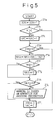
- Figure 5 is a flowchart for a second preignition detecting subroutine;
- Figure 6A - 6D are is a diagrams for explaining the operation in the second preignition detecting subroutine;
- Figure 7 is a diagram showing a relationship between the frequency of occurrence of abnormal vibration and engine speed; and
- Figure 8 is a diagram showing a relationship between the occurrence of preignition and an air/fuel ratio.
- Figure 1 is a diagram showing the configuration of a preignition detection apparatus according to the present invention. An
internal combustion engine 10 has apiston 103 which moves up and down in acylinder 102 bored in acylinder block 101. - An
intake valve 104, anexhaust valve 105, and aspark plug 106 are mounted on the top of thecylinder 102, an air/fuel mixture, drawn through theintake valve 104 and compressed by the upward movement of thepiston 103, is ignited by thespark plug 106 and is caused to expand, forcing thepiston 103 downward and thus generating power. - The up and down motion of the piston is converted to rotary motion by means of a crankshaft (not shown). A
timing rotor 107 is attached to the forward end of the crankshaft. - The
timing rotor 107 has a total of 12 teeth formed at intervals of 30°, and as each tooth of thetiming rotor 107 passes, a pulse is outputted from acrankshaft position sensor 111 mounted in close proximity to thetiming rotor 107. In this way, the crankshaft angle can be detected every 30° by means of thecrankshaft position sensor 111. - An intake camshaft (not shown) which drives the
intake valve 104 is equipped with a protruding tab, and as the protruding tab passes, a pulse is outputted from acamshaft sensor 112 mounted in close proximity to the intake camshaft. In this way, one revolution of the camshaft, i.e., one cycle of the internal combustion engine, can be detected by means of thecamshaft sensor 112. - Further, a
vibration sensor 113 is mounted in thecylinder block 101 to detect vibration occurring in the internal combustion engine. - Outputs of the
crankshaft position sensor 111,camshaft sensor 112, andvibration sensor 113 are fetched into acontroller 12. - The
controller 12 is constructed from a microcomputer consisting of aCPU 122, amemory 123, aninput interface 124, and anoutput interface 125, which are interconnected by adata bus 121. The output of each sensor is fetched into theCPU 122 via theinput interface 124. - The
output interface 125 of thecontroller 12 outputs an ignition command signal which is supplied to thespark plug 106 via anigniter 131 and anignition coil 132. - Besides the previously described preignition, knocking also causes engine vibration and knocking occurs when a residual combustible gas in the
cylinder 102 self-ignites after sparking of thespark plug 106. When the engine is not operated under a condition where preignition may occur, that is, when the engine is not operated under high-temperature and high-load conditions, preignition does not occur. Accordingly, the detection of preignition is performed in an ignition timing control routine for inhibiting knocking. - Figure 2 is a flowchart of the ignition timing control routine executed in the
controller 12. This routine is executed every fixed interval. - At
step 20, output R of thevibration sensor 113 mounted in thecylinder block 101 is read, and atstep 21, a vibration level K is determined as a function of the output R of thevibration sensor 113.
- For example, the moving average of the output R of the
vibration sensor 113 can be used for determining the vibration level. - At
step 22, it is determined whether or not the vibration level K is greater than or equal to a predetermined threshold value ∈, to determine whether or not the engine is experiencing abnormal vibration. - When the determination at
step 22 is negative, that is, when the engine is not experiencing abnormal vibration, an adjustment value ΔTad for adjusting a reference ignition timing TI is decreased by a prescribed advancing amount ΔTL atstep 23 before proceeding tostep 25.
- Conversely, when the determination at
step 22 is affirmative, that is, when the engine is experiencing abnormal vibration, the adjustment value ΔTad is increased by a prescribed lagging amount ΔTD atstep 25 before proceeding tostep 25.
- At
step 25, the adjustment value ΔTad is subtracted from the reference ignition timing TI, thereby advancing or retarding the ignition angle to determine the ignition timing T.
- As is known, the reference ignition timing TI is calculated as a function of engine speed Ne and intake air flow rate Qa.

- Here, to quickly suppress abnormal engine vibration, the value of the prescribed retardation amount ΔTD is made larger than the value of the prescribed advancing amount ΔTL.
- At
step 26, the ignition timing T is limited between predetermined most retarded timing TD and the reference ignition timing TI, and the control proceeds tostep 27. - At
step 27, a preignition detecting subroutine is executed, and then the routine is terminated. - Figure 3 is a flowchart illustrating the first preignition detecting subroutine executed at
step 27. Atstep 27A, it is determined whether or not the vibration level K is greater than the predetermined threshold value ∈. - When the determination at
step 27A is affirmative, that is, when the engine is experiencing abnormal vibration, a non-abnormal-vibration interval counter NVC, which indicates a period free from abnormal vibration, is reset to "0", before proceeding tostep 27E. - When the determination at
step 27A is negative, that is, when the engine is not experiencing abnormal vibration, then the non-abnormal vibration interval counter NVC is incremented atstep 27C, and limited to less than an upper limit value atstep 27D, before proceeding tostep 27E. - The reason for limiting the non-abnormal vibration interval counter NVC to less than an upper limit value is as follows.
- That is, when abnormal engine vibration occurs frequently, the non-abnormal vibration interval counter NVC is frequently reset, and it does not exceed a predetermined non-abnormal-vibration period PNV.
- Conversely, as long as abnormal engine vibration does not occur, the non-abnormal vibration interval counter NVC continues to increase. The non-abnormal-vibration interval counter actually incorporated in the
controller 12 is reset to "0" when it reaches a maximum countable value, and then starts to increase again. Accordingly, if abnormal vibration was detected immediately after the non-abnormal vibration interval counter NVC was reset to "0" because abnormal engine vibration did not occur for a long period of time, it may be determined by mistake that abnormal engine vibration has been occurring frequently. To prevent such a faulty determination, it becomes necessary to maintain the non-abnormal-vibration interval counter NVC at the upper limit value when abnormal engine vibration has not occurred for a long period. - At
step 27E, it is determined whether or not the count value of the non-abnormal vibration interval counter NVC has exceeded the non-abnormal vibration period PNV. - When the determination at
step 27E is affirmative, that is, when abnormal engine vibration has not occurred for a long period, a frequent vibration continuing interval counter FVC, which indicates a period for which the engine is experiencing abnormal vibration at frequent intervals, is reset to "0" at step 27F before proceeding to step 27I. - Conversely, when the determination at
step 27E is negative, that is, when the engine is experiencing abnormal vibration at frequent intervals, the frequent vibration continuing interval counter FVC is incremented atstep 27G, and limited to less than an upper limit value instep 27H, before proceeding to step 27I. - The reason for limiting the frequent vibration continuing interval counter FVC to less than an upper limit value is similar to the reason for limiting the non-abnormal vibration interval counter NVC to less than an upper limit value, that is, a faulty determination that the engine is not experiencing abnormal vibration at frequent intervals is prevented from being made when the frequent vibration continuing interval counter FVC is reset after reaching its maximum countable value.
- At step 27I, it is determined whether or not the count value of the frequent vibration continuing interval counter FVC is greater than a predetermined preignition determination value PJ.
- When the determination at step 27I is affirmative, that is, when the count value of the frequent vibration continuing interval counter FVC is greater than the predetermined preignition determination value PJ, it is determined that preignition has occurred, and a warning is issued at
step 27J, an operation for avoiding preignition is executed atstep 27K, and then this subroutine is terminated. - Conversely, when the determination at step 27I is negative, that is, when the count value of the frequent vibration continuing interval counter FVC is not greater than the predetermined preignition determination value PJ, it is determined that preignition has not been encountered, and this subroutine is immediately terminated.
- Figure 4A - 4A are diagrams for explaining the operation in the first preignition detecting subroutine. Engine vibration, the count value of the non-abnormal-vibration interval counter NVC, the count value of the frequent vibration continuing interval counter FVC, and the ignition timing are shown in this order from the top to the bottom. Time is plotted along the abscissa.
- Consider the case in which monitoring is started at time t0 and abnormal vibration is detected at times t2, t4 to t5, t7, t9, and t10 to t12.
- That is, after time t0, the non-abnormal-vibration interval counter NVC and the frequent vibration continuing interval counter FVC are incremented.
- Since no abnormal vibration is detected until t2, the count value of the non-abnormal-vibration interval counter NVC exceeds the non-abnormal-vibration duration period PNV, and the frequent vibration continuing interval counter FVC is reset at time t1 so that its count value does not exceed the preignition determination value PJ.
- At time t2, abnormal vibration happens and the non-abnormal-vibration interval counter NVC is reset and starts to increment again. The operation from t2 to t4 is the same as that from t0 to t2.
- From time t4 to t5, abnormal vibration occurs in succession, so that the non-abnormal-vibration interval counter NVC is reset frequently and the count value of the frequent vibration continuing interval counter FVC continues to increase. Because the abnormal vibration stops after time t5, the non-abnormal-vibration interval counter NVC is reset and starts to increase again. At time t6, the counter goes over the non-abnormal-vibration period PNV, and the frequent vibration continuing interval counter FVC is reset. Accordingly, the frequent vibration continuing interval counter FVC does not exceed the preignition determination value PJ, and it is not determined that preignition has occurred.
- Since abnormal vibration also occurs in succession from t9 to t12, the non-abnormal-vibration interval counter NVC is reset frequently and the count value of the frequent vibration continuing interval counter FVC continues to increase. The frequent vibration continuing interval counter FVC exceeds the preignition determination value PJ at time t11, and here it is determined that preignition has occurred.
- From time t0 to t10, the air-fuel mixture in the cylinder fires with a certain delay after the ignition of the
spark plug 106. The firing timing gradually approaches the ignition timing after time t10 and the air-fuel mixture fires before the ignition of thespark plug 106, that is, preignition continuously occurs. - The non-abnormal-vibration period PNV and the preignition determination value PJ are previously fixed values in the above embodiment, but the non-abnormal-vibration period PNV and the preignition determination value PJ may be determined based on the learning values of the non-abnormal-vibration interval counter NVC and frequent vibration continuing interval counter FVC, respectively.
- In that case, it becomes possible to compensate for differences in antiknock characteristics of fuel (for example, due to changeover between regular gasoline and high octane gasoline) and variations in abnormal vibration occurrence characteristics due to variations in temperature, humidity, and other environmental conditions.
- Furthermore, by making a decision based on the ratios of the present non-abnormal-vibration duration period PNV and preignition determination value PJ to the respective learning values, variations in the detecting characteristics of the
vibration sensor 113 can also be compensated. - As described above, according to the first preignition detecting subroutine, preignition can be detected almost at the same time as the preignition actually occurs.
- However, when the condition just before preignition may occur is maintained, and abnormal vibration has not been detected for the specified period, the frequent vibration duration interval counter FVC is reset. Therefore, the detection of preignition may be delayed when a condition where abnormal vibration occurs frequently is established, because preignition cannot be detected until abnormal vibration is continuously detected for a specified period after it begins.
- Figure 5 is a flowchart illustrating a second preignition detecting subroutine which is designed to overcome the above problem, and which is executed in place of the first preignition detecting subroutine at
step 27 of the ignition timing control routine. - At
step 27a, ignition count counter IGN is incremented, and atstep 27b, it is determined whether or not the vibration level K is greater than the predetermined threshold value ε. - When the determination at step 276 is affirmative, that is, when the engine is experiencing abnormal vibration, the abnormal vibration occurrence counter NKC is incremented at
step 27c before control proceeds to step 27d. When the determination atstep 27b is negative, that is, when the engine is not experiencing abnormal vibration, the control proceeds directly to step 27d. - At
step 27d, it is determined whether or not the ignition count counter IGN is less than a predetermined ignition count N1. When the determination atstep 27d is affirmative, that is, when the ignition count is less than the predetermined ignition count, this subroutine is immediately terminated. - Note, if the predetermined ignition count N1 is set to a large value, variations in the number of occurrences of abnormal vibration detected while N1 ignitions are executed will be reduced and the detecting accuracy will improve, but the time that elapses before detecting of preignition will become long. Therefore, the predetermined ignition count N1 must be determined in accordance with the tradeoff between detecting accuracy and detecting time.
- When the determination at
step 27d is negative, that is, when the ignition count has reached the predetermined ignition count, processing fromstep 27e through step 27j is carried out. - At
step 27e, an abnormal vibration accumulated value NKA which is a accumulated sum of the differences between the number of occurrences of abnormal vibration, detected while the predetermined times ignitions are executed, and a predetermined abnormal vibration occurrence count N2 is calculated.
- That is, as the number of occurrences of abnormal vibration detected, while the predetermined ignitions are executed, increases, the count value of the abnormal vibration occurrence counter NKC increases and the abnormal vibration cumulative value NKA also increases.
- Note, the predetermined abnormal vibration occurrence count N2 is a threshold value for determining that abnormal vibration has been occurring frequently. Normally, this value should be determined by multiplying the predetermined ignition count by a target abnormal vibration occurrence frequency based on which control for suppressing abnormal vibration is to be performed. However, since the predetermined ignition count is set to a relatively small value, for example, 50, the actual value of the predetermined abnormal vibration occurrence count N2 is determined by first multiplying the predetermined ignition count by the target abnormal vibration occurrence frequency based on which control for suppressing abnormal vibration is to be performed, and then multiplying the resulting product by a safety coefficient α of 1.0 or larger. That is, the following equation is used.

- At
steps - At
step 27h, it is determined whether or not the abnormal vibration accumulated value NKA is less than a preignition occurrence value NP. - When the determination at 27h is negative, that is, when the abnormal vibration accumulated value NKA is not less than the preignition occurrence value NP, a preignition warning is issued and an operation for avoiding preignition is performed at
step 27i before proceeding to step 27j. Conversely, when the determination at 27h is affirmative, that is, when the abnormal vibration cumulative value NKA is less than the preignition occurrence value NP, the control proceeds directly to step 27j. - At step 27j, the ignition count counter IGN and the abnormal vibration occurrence counter NKC are reset, and this subroutine is terminated.
- Note, the abnormal vibration accumulated value NKA is not reset in step 27j, but this is to detect preignition as soon as possible when preignition frequently occurs.
- In the second preignition detection process, it would be desirable to set the safety coefficient α as close to 1.0 as possible from the viewpoint of enhancing the detecting accuracy, but this would require that the predetermined ignition count N1 is set to a large value to accelerate the detection.
- One way to bring the safety coefficient a close to 1.0 while maintaining the detection speed is by dividing the predetermined ignition count N1 by n, updating the number of occurrences of abnormal vibration every (Nl/n) ignition count, and by making a decision on preignition based on the number of occurrences of abnormal vibration detected while the ignition count N1.
- Further, in the second preignition detecting subroutine, attention is directed only to the number of occurrences of abnormal vibration. But when the level of abnormal vibration is large, it is also possible to take into account the level of the vibration by multiplying the number of occurrences by an appropriate factor, for example, 1.5.
- Figure 6A - 6D are diagrams for explaining the operation in the second preignition detecting subroutine. The count value of the abnormal vibration occurrence counter, the count value of the abnormal vibration occurrence counter minus the value of the predetermined abnormal vibration occurrence count, the abnormal vibration accumulated value, and the ignition timing are shown in this order from the top to the bottom. Time is plotted along the abscissa.
- The figure shows the case in which an increase in the number of occurrences of abnormal vibration is detected at times t1, t2, t3, and t4 to t7, that is, the value (NKC-N2) becomes positive at the respective times.
- At times t1, t2, and t3, the abnormal vibration accumulated value increases, but thereafter the abnormal vibration accumulated value decreases, that is, the value (NKC-N2) becomes negative and, hence, the abnormal vibration accumulated value becomes "0".
- However, between time t4 and time t7, the number of occurrences of abnormal vibration increases continuously, so that the abnormal vibration accumulated value gradually increases, exceeds the preignition occurrence value NP at time t5, and it is decided that preignition has occurred.
- From time t0 to time t6, the actual ignition of the air-fuel mixture occurs later than the ignition timing and it is determined that preignition does not occur, but after time t6, the actual ignition occurs earlier than the ignition timing, and it is determined that preignition has occurred.
- According to the second preignition detecting process, it is determined that preignition has occurred at time t5 before time t6, and preignition can be detected in an incipient stage.
- Since a condition where preignition may occur is always accompanied by frequent occurrences of abnormal vibration, it is possible to certainly detect a condition where preignition may occur though an ignition timing is controlled so that it is delayed to suppress abnormal vibration.
- In the above embodiment, the preignition determination value PJ and the preignition occurrence value NP are fixed over the entire operating range of the engine, but in that case, there may occur an erroneous decision or a delay in detection.
- Figure 7 is a diagram showing a relationship between the frequency of occurrence of abnormal vibration and engine speed, and the engine speed is plotted along the abscissa and the frequency of occurrence of abnormal vibration along the ordinate. As shown, the frequency of occurrence of abnormal vibration varies greatly depending on the engine speed because, for example, the charging efficiency varies depending on the engine speed.
- Accordingly, when the preignition determination value PJ and the preignition occurrence value NP are determined based upon the conditions of the low-speed range A, there occurs a delay in detecting preignition in the mid-speed range B or high-speed range C.
- Conversely, when the preignition determination value PJ and the preignition occurrence value NP are determined based upon the conditions of the mid-revolution range B or high-revolution range C, it may be incorrectly determined that preignition occurs as soon as abnormal vibration has occurred.
- One way to solve this problem is to map the preignition determination value PJ and preignition occurrence value NP according to the engine speed. Alternatively, preignition detection may be limited to the mid- and high-speed ranges, considering the fact that preignition is not likely to occur in the low-speed range.
- The above-described process detects abnormal vibration collectively for all the cylinders of the engine with one sensor. It may be possible to improve detecting accuracy by detecting abnormal vibration at every cylinder because the amount of adhering deposits, which function as hotspots, depends upon the cylinder.
- In some internal combustion engines, a cylinder internal pressure sensor or an ion sensor for detecting an ion current is provided for each cylinder to detect conditions that can induce preignition, but, providing such a sensor for each cylinder is disadvantageous from the viewpoint of economy and construction, and it is only possible to detect a hot spot near the sensor using the ion sensor.
- According to the preignition detecting apparatus of the present invention, on the other hand, preignition can be detected quickly without specifically providing any additional sensor.
- In a preignition detecting apparatus designed to detect preignition based on the timing of the occurrence of abnormal vibration, the timing to detect abnormal vibration must be controlled to avoid incorrect determination due to noise associated with the opening and closing of intake and exhaust valves, etc. This inevitably leads to increased complexity of the construction.
- Though it is possible to determine that preignition has occurred when the amplitude of abnormal vibration (the frequency of occuring abnormal vibration) increases, not only the construction becomes more complex, but also detecting time becomes longer.
- Conversely, the preignition detecting apparatus according to the present invention is not only simple in its construction, but it also detects preignition at an early stage.
- There are several method of avoiding preignition, among them:
- 1. Set the ignition timing to the most retarded timing TD.
- 2. Reduce the intake air flow rate.
- 3. Change the air-fuel ratio.
- 4. Cut-off the fuel.
- While fuel cut-off is the most reliable method to avoid preignition, vehicle drivability is inevitably deteriorated.
- According to the preignition detecting apparatus of the present invention, since conditions causing or likely to cause preignition can be evaluated based on the abnormal vibration accumulated value NKA, it is also possible to suppress preignition by changing the air-fuel ratio according to the abnormal vibration accumulated value NKA.
- Figure 8 is a diagram showing a relationship between the occurrence of preignition and air-fuel ratio, with load plotted along the ordinate and air/fuel ratio along the abscissa.
- As can be seen from this figure, preignition easily occurs when the air-fuel ratio is set at b which is a point slightly deviated to the rich side from the stoichiometric air-fuel ratio (14.5).
- Since the air-fuel ratio is normally controlled at the stoichiometric air-fuel ratio to facilitate purification of an exhaust gas, it is necessary to set an air-fuel ratio to more lean than "c", that is, the stoichiometric air-fuel ratio or to richer than "a" corresponding to the stoichiometric air-fuel ratio to suppress preignition.
- In situations where the air-fuel ratio cannot be changed abruptly because of the need to maintain drivability, the air-fuel ratio should be set outside the range a to c.
- In practice, it is desirable to set the air fuel ratio to an upper limit or lower limit value, a marginal region that can still achieve combustion, that is, the shaded regions (regions where preignition does not occur irrespective of the load) at both ends of Figure 8.
Claims (12)
- A preignition detecting apparatus comprising:a vibration detecting means for detecting vibration of an internal combustion engine;an abnormal vibration occurrence interval measuring means for measuring a time interval while abnormal vibration higher than a predetermined level is being detected by said vibration detecting means;a frequent vibration continuing internal measuring means for measuring a time interval while the abnormal vibration occurrence interval measured by said abnormal vibration occurrence interval measuring means is shorter than a predetermined non-abnormal vibration continuing interval; anda preignition determining means for determining that preignition has occurred when the frequent vibration continuing internal measured by said frequent vibration continuing internal measuring means becomes longer than a predetermined preignition determining interval.
- A preignition detecting apparatus of claim 1, wherein,
said frequent vibration continuing internal measuring means uses a non-abnormal vibration continuing interval determined in accordance with a non-abnormal vibration interval while a non-abnormal vibration lower than the predetermined level is being detected by said vibration detecting means. - A preignition detecting apparatus of claim 1, wherein,
said frequent vibration continuing internal measuring means uses a non-abnormal vibration continuing interval which becomes longer as an engine speed becomes lower. - A preignition detecting apparatus of claim 1, wherein,
said preignition determining means uses a preignition determining interval determined in accordance with a frequent vibration continuing internal. - A preignition detecting apparatus comprising:a vibration detecting means for detecting vibration of an internal combustion engine;an abnormal vibration occurrence frequency calculating means for calculating a frequency in detecting of abnormal vibration higher than a predetermined level by said vibration detecting means;an accumulating means for accumulating the frequency calculated by said abnormal vibration occurrence frequency calculating means; anda preignition determining means for determining that preignition has occurred when the accumulated frequency becomes larger than a predetermined preignition determining value.
- A preignition detecting apparatus of claim 5, wherein,
said preignition determining means uses a preignition determining value which becomes larger as an engine speed becomes lower. - A preignition detecting method comprising steps of:a vibration detecting step for detecting vibration of an internal combustion engine;an abnormal vibration occurrence interval measuring step for measuring a time interval while abnormal vibration higher than a predetermined level is being detected at said vibration detecting step;a frequent vibration continuing internal measuring step for measuring a time interval while the abnormal vibration occurrence interval measured at said abnormal vibration occurrence interval measuring step is shorter than a predetermined non-abnormal vibration continuing interval; anda preignition determining step for determining that preignition has occurred when the frequent vibration continuing internal measured at said frequent vibration continuing internal measuring step becomes longer than a predetermined preignition determining interval.
- A preignition detecting method of claim 7, wherein,
said frequent vibration continuing internal measuring step uses a non-abnormal vibration continuing interval determined in accordance with a non-abnormal vibration interval while a non-abnormal vibration lower than the predetermined level is being detected at said vibration detecting step. - A preignition detecting step of claim 7, wherein,
said frequent vibration continuing internal measuring step uses a non-abnormal vibration continuing interval which becomes longer as an engine speed becomes lower. - A preignition detecting method of claim 7, wherein,
said preignition determining step uses a preignition determining interval determined in accordance with a frequent vibration continuing internal. - A preignition detecting method comprising steps of:a vibration detecting step for detecting vibration of an internal combustion engine;an abnormal vibration occurrence frequency calculating step for calculating a frequency in detecting of abnormal vibration higher than a predetermined level at said vibration detecting step;an accumulating step for accumulating the frequency calculated at said abnormal vibration occurrence frequency calculating step; anda preignition determining step for determining that preignition has occurred when the accumulated frequency becomes larger than a predetermined preignition determining value.
- A preignition detecting method of claim 11, wherein,
said preignition determining step uses a preignition determining value which becomes larger as an engine speed becomes lower.
Priority Applications (1)
| Application Number | Priority Date | Filing Date | Title |
|---|---|---|---|
| EP02014724A EP1260806B1 (en) | 1996-07-15 | 1997-07-02 | A preignition detection apparatus |
Applications Claiming Priority (3)
| Application Number | Priority Date | Filing Date | Title |
|---|---|---|---|
| JP184994/96 | 1996-07-15 | ||
| JP08184994A JP3116826B2 (en) | 1996-07-15 | 1996-07-15 | Preignition detection device |
| JP18499496 | 1996-07-15 |
Related Child Applications (1)
| Application Number | Title | Priority Date | Filing Date |
|---|---|---|---|
| EP02014724A Division EP1260806B1 (en) | 1996-07-15 | 1997-07-02 | A preignition detection apparatus |
Publications (3)
| Publication Number | Publication Date |
|---|---|
| EP0819925A2 true EP0819925A2 (en) | 1998-01-21 |
| EP0819925A3 EP0819925A3 (en) | 1999-06-09 |
| EP0819925B1 EP0819925B1 (en) | 2003-04-09 |
Family
ID=16162933
Family Applications (2)
| Application Number | Title | Priority Date | Filing Date |
|---|---|---|---|
| EP97401555A Expired - Lifetime EP0819925B1 (en) | 1996-07-15 | 1997-07-02 | A preignition detection apparatus |
| EP02014724A Expired - Lifetime EP1260806B1 (en) | 1996-07-15 | 1997-07-02 | A preignition detection apparatus |
Family Applications After (1)
| Application Number | Title | Priority Date | Filing Date |
|---|---|---|---|
| EP02014724A Expired - Lifetime EP1260806B1 (en) | 1996-07-15 | 1997-07-02 | A preignition detection apparatus |
Country Status (5)
| Country | Link |
|---|---|
| US (1) | US5905193A (en) |
| EP (2) | EP0819925B1 (en) |
| JP (1) | JP3116826B2 (en) |
| DE (2) | DE69727992T2 (en) |
| ES (2) | ES2219604T3 (en) |
Cited By (12)
| Publication number | Priority date | Publication date | Assignee | Title |
|---|---|---|---|---|
| WO2000037796A1 (en) * | 1998-12-22 | 2000-06-29 | Robert Bosch Gmbh | Engine control device |
| EP1116946A3 (en) * | 2000-01-13 | 2002-05-22 | Ford Global Technologies, Inc. | Controlling an internal combustion engine using an engine-mounted acceleratometer |
| DE102007024415B3 (en) * | 2007-05-21 | 2009-01-02 | Continental Automotive Gmbh | Ignition recognition method for a spark-ignited internal combustion engine in which ignition of the cylinder is recognized when the rotational speed of the crankshaft is slowed compared to a reference value |
| EP2256326A1 (en) | 2009-05-19 | 2010-12-01 | Bayerische Motoren Werke | Method and device for recognising faulty spark formation of an externally ignited combustion engine with one or more cylinders |
| US7861689B2 (en) | 2007-05-21 | 2011-01-04 | Continental Automotive Gmbh | Method for controlling an internal combustion engine |
| WO2011117122A3 (en) * | 2010-03-25 | 2012-01-05 | Robert Bosch Gmbh | Method and device for handling uncontrolled combustion in an internal combustion engine of a motor vehicle |
| US8245692B2 (en) | 2010-12-03 | 2012-08-21 | Ford Global Technologies, Llc | Method and system for pre-ignition control |
| DE102012221249B3 (en) * | 2012-11-21 | 2014-03-20 | Continental Automotive Gmbh | Method and device for detecting pre-ignition in an internal combustion engine |
| DE102012221245A1 (en) | 2012-11-21 | 2014-05-22 | Continental Automotive Gmbh | Method and device for detecting pre-ignition in an internal combustion engine |
| FR3072710A1 (en) * | 2017-10-20 | 2019-04-26 | Psa Automobiles Sa | METHOD FOR DETERMINING SENSITIVITY OF ENGINE TO PRELIGHTS |
| EP3637083A1 (en) * | 2018-10-11 | 2020-04-15 | Hyundai Motor Company | Failure diagnosis method for power train components |
| CN115126613A (en) * | 2021-03-29 | 2022-09-30 | 广州汽车集团股份有限公司 | Engine pre-ignition control method, device and computer storage medium |
Families Citing this family (63)
| Publication number | Priority date | Publication date | Assignee | Title |
|---|---|---|---|---|
| JP4431927B2 (en) * | 2001-02-20 | 2010-03-17 | 株式会社デンソー | Ignition system control method |
| JP3659589B2 (en) * | 2002-10-21 | 2005-06-15 | 三菱電機株式会社 | Knock control device for internal combustion engine |
| US6914524B2 (en) * | 2003-02-27 | 2005-07-05 | Delphi Technologies, Inc. | Apparatus and method for detecting ignition and engine conditions |
| FR2879665B1 (en) * | 2004-12-17 | 2009-12-18 | Inst Francais Du Petrole | ABNORMAL COMBUSTION DETECTION METHOD FOR INTERNAL COMBUSTION ENGINES |
| US7650238B2 (en) * | 2005-05-09 | 2010-01-19 | Northrop Grumman Corporation | Environmental characteristic determination |
| DE102005059575B4 (en) * | 2005-12-14 | 2022-03-17 | Robert Bosch Gmbh | Method for operating an internal combustion engine |
| US7302932B2 (en) * | 2006-03-17 | 2007-12-04 | Ford Global Technologies, Llc | Pre-ignition detection and mitigation |
| FR2905142B1 (en) * | 2006-08-28 | 2008-10-24 | Inst Francais Du Petrole | REAL-TIME ESTIMATION METHOD OF INDICATORS OF COMBUSTION CONDITION OF AN INTERNAL COMBUSTION ENGINE |
| JP2010084617A (en) * | 2008-09-30 | 2010-04-15 | Mazda Motor Corp | Control device for engine |
| DE102010004091B4 (en) | 2010-01-07 | 2026-04-16 | Volkswagen Aktiengesellschaft | Method for operating an internal combustion engine |
| JP5576141B2 (en) * | 2010-02-15 | 2014-08-20 | 株式会社日本自動車部品総合研究所 | Control device for internal combustion engine |
| US8851050B2 (en) | 2010-03-31 | 2014-10-07 | Mazda Motor Corporation | Spark-ignition engine control method and system |
| US8463533B2 (en) * | 2010-08-05 | 2013-06-11 | Ford Global Technologies, Llc | Method and system for pre-ignition control |
| US8260530B2 (en) | 2010-08-05 | 2012-09-04 | Ford Global Technologies, Llc | Method and system for pre-ignition control |
| US8073613B2 (en) * | 2010-08-05 | 2011-12-06 | Ford Global Technologies, Llc | Method and system for pre-ignition control |
| DE102010040271A1 (en) * | 2010-09-06 | 2012-03-08 | Robert Bosch Gmbh | Method and device for setting an emergency operation in a faulty system for detecting pre-ignition in an internal combustion engine |
| US9845752B2 (en) | 2010-09-29 | 2017-12-19 | GM Global Technology Operations LLC | Systems and methods for determining crankshaft position based indicated mean effective pressure (IMEP) |
| US8683976B2 (en) | 2011-02-16 | 2014-04-01 | Ford Global Technologies, Llc | Spark plug degradation detection |
| US8095297B2 (en) * | 2011-03-24 | 2012-01-10 | Ford Global Technologies, Llc | Method and system for pre-ignition control |
| JP5832130B2 (en) | 2011-04-20 | 2015-12-16 | 三菱電機株式会社 | Control device for internal combustion engine |
| US8156923B2 (en) * | 2011-04-20 | 2012-04-17 | Ford Global Technologies, Llc | Method and system for pre-ignition control |
| US9127604B2 (en) | 2011-08-23 | 2015-09-08 | Richard Stephen Davis | Control system and method for preventing stochastic pre-ignition in an engine |
| US9097196B2 (en) * | 2011-08-31 | 2015-08-04 | GM Global Technology Operations LLC | Stochastic pre-ignition detection systems and methods |
| US9038596B2 (en) | 2011-12-02 | 2015-05-26 | Ford Global Technologies, Llc | Method and system for pre-ignition control |
| JP5464202B2 (en) | 2011-12-12 | 2014-04-09 | 株式会社デンソー | Electronic control device for internal combustion engine |
| JP5561283B2 (en) * | 2012-01-11 | 2014-07-30 | 株式会社デンソー | Sensor signal processing device |
| JP5395201B2 (en) * | 2012-03-14 | 2014-01-22 | 三菱電機株式会社 | Knock control device for internal combustion engine |
| DE102012005227A1 (en) * | 2012-03-15 | 2013-09-19 | Volkswagen Aktiengesellschaft | A method for preventing a pre-ignition of a fuel-air mixture in a cylinder chamber of an internal combustion engine |
| JP2013230718A (en) * | 2012-04-27 | 2013-11-14 | Mazda Motor Corp | Exhaust gas purification device and control method of internal combustion engine |
| US9551288B2 (en) | 2012-06-29 | 2017-01-24 | Ford Global Technologies, Llc | Method and system for pre-ignition control |
| US9043122B2 (en) | 2012-06-29 | 2015-05-26 | Ford Global Technologies, Llc | Method and system for pre-ignition control |
| US8997723B2 (en) | 2012-06-29 | 2015-04-07 | Ford Global Technologies, Llc | Method and system for pre-ignition control |
| US9133775B2 (en) | 2012-08-21 | 2015-09-15 | Brian E. Betz | Valvetrain fault indication systems and methods using engine misfire |
| US9121362B2 (en) | 2012-08-21 | 2015-09-01 | Brian E. Betz | Valvetrain fault indication systems and methods using knock sensing |
| US9376975B2 (en) * | 2012-12-12 | 2016-06-28 | GM Global Technology Operations LLC | Stochastic pre-ignition prediction and mitigation systems and methods |
| US8973429B2 (en) | 2013-02-25 | 2015-03-10 | GM Global Technology Operations LLC | System and method for detecting stochastic pre-ignition |
| US9267484B2 (en) | 2013-03-14 | 2016-02-23 | Ford Global Technologies, Llc | Method and system for pre-ignition control |
| US20140297164A1 (en) * | 2013-04-01 | 2014-10-02 | GM Global Technologies Operations LLC | Stochastic pre-ignition (spi) mitigation using an adaptive spi scaler |
| US10196999B2 (en) * | 2013-12-05 | 2019-02-05 | Ford Global Technologies, Llc | Method and system for pre-ignition control |
| JP6221948B2 (en) * | 2014-06-05 | 2017-11-01 | トヨタ自動車株式会社 | Control device for internal combustion engine |
| US9556810B2 (en) | 2014-12-31 | 2017-01-31 | General Electric Company | System and method for regulating exhaust gas recirculation in an engine |
| US9752949B2 (en) | 2014-12-31 | 2017-09-05 | General Electric Company | System and method for locating engine noise |
| US9803567B2 (en) | 2015-01-07 | 2017-10-31 | General Electric Company | System and method for detecting reciprocating device abnormalities utilizing standard quality control techniques |
| US9874488B2 (en) | 2015-01-29 | 2018-01-23 | General Electric Company | System and method for detecting operating events of an engine |
| US9528445B2 (en) | 2015-02-04 | 2016-12-27 | General Electric Company | System and method for model based and map based throttle position derivation and monitoring |
| US9903778B2 (en) | 2015-02-09 | 2018-02-27 | General Electric Company | Methods and systems to derive knock sensor conditions |
| US9791343B2 (en) | 2015-02-12 | 2017-10-17 | General Electric Company | Methods and systems to derive engine component health using total harmonic distortion in a knock sensor signal |
| US10001077B2 (en) | 2015-02-19 | 2018-06-19 | General Electric Company | Method and system to determine location of peak firing pressure |
| US9915217B2 (en) | 2015-03-05 | 2018-03-13 | General Electric Company | Methods and systems to derive health of mating cylinder using knock sensors |
| US9695761B2 (en) | 2015-03-11 | 2017-07-04 | General Electric Company | Systems and methods to distinguish engine knock from piston slap |
| US9435244B1 (en) | 2015-04-14 | 2016-09-06 | General Electric Company | System and method for injection control of urea in selective catalyst reduction |
| US9784231B2 (en) | 2015-05-06 | 2017-10-10 | General Electric Company | System and method for determining knock margin for multi-cylinder engines |
| US9933334B2 (en) | 2015-06-22 | 2018-04-03 | General Electric Company | Cylinder head acceleration measurement for valve train diagnostics system and method |
| US9784635B2 (en) | 2015-06-29 | 2017-10-10 | General Electric Company | Systems and methods for detection of engine component conditions via external sensors |
| US10393609B2 (en) | 2015-07-02 | 2019-08-27 | Ai Alpine Us Bidco Inc. | System and method for detection of changes to compression ratio and peak firing pressure of an engine |
| US9897021B2 (en) | 2015-08-06 | 2018-02-20 | General Electric Company | System and method for determining location and value of peak firing pressure |
| JP6657792B2 (en) * | 2015-10-30 | 2020-03-04 | 三菱自動車工業株式会社 | Engine control device |
| US9903334B2 (en) | 2016-05-10 | 2018-02-27 | Fca Us Llc | Low speed pre-ignition knock detection |
| US10760543B2 (en) | 2017-07-12 | 2020-09-01 | Innio Jenbacher Gmbh & Co Og | System and method for valve event detection and control |
| JP7183915B2 (en) * | 2019-03-29 | 2022-12-06 | トヨタ自動車株式会社 | Hybrid vehicle and its control method |
| US10823098B1 (en) | 2019-04-18 | 2020-11-03 | Fca Us Llc | Low speed pre-ignition knock detection, mitigation, and driver notification |
| US11982248B2 (en) * | 2021-10-25 | 2024-05-14 | Transportation Ip Holdings, Llc | Methods and systems for diagnosing engine cylinders |
| JP2025043561A (en) * | 2023-09-19 | 2025-04-01 | トヨタ自動車株式会社 | Preignition determination device for internal combustion engine |
Family Cites Families (17)
| Publication number | Priority date | Publication date | Assignee | Title |
|---|---|---|---|---|
| DE3050875C2 (en) * | 1979-06-15 | 1992-05-27 | Nissan Motor Co., Ltd., Yokohama, Kanagawa | Device for detecting knocking phenomena of an internal combustion engine |
| JPS5637535A (en) * | 1979-09-05 | 1981-04-11 | Nippon Soken Inc | Knocking detector |
| JPS58214835A (en) * | 1982-06-07 | 1983-12-14 | Toyota Motor Corp | Knocking decision for engine |
| EP0102779A3 (en) * | 1982-08-12 | 1985-05-08 | Bl Technology Limited | Method and apparatus for detecting knock in a spark ignition engine |
| JPH0542574Y2 (en) * | 1987-12-02 | 1993-10-27 | ||
| EP0443708A2 (en) * | 1990-02-21 | 1991-08-28 | Stresswave Technology Limited | An apparatus for controlling an internal combustion engine |
| KR940004351B1 (en) * | 1990-09-27 | 1994-05-23 | 미쓰비시덴키가부시키가이샤 | Knock detector |
| KR940004352B1 (en) * | 1990-10-02 | 1994-05-23 | 미쓰비시덴키가부시키가이샤 | Rust control device of internal combustion engine |
| US5204630A (en) * | 1991-06-26 | 1993-04-20 | Allied Signal Inc. | Preignition warning device |
| US5608633A (en) * | 1991-07-29 | 1997-03-04 | Nissan Motor Co., Ltd. | System and method for detecting knocking for internal combustion engine |
| JPH05157033A (en) * | 1991-11-29 | 1993-06-22 | Honda Motor Co Ltd | Ignition timing control device for internal combustion engine |
| JP3084889B2 (en) * | 1992-03-12 | 2000-09-04 | 株式会社デンソー | Knock control device for internal combustion engine |
| JP3668497B2 (en) * | 1992-09-30 | 2005-07-06 | 株式会社日立製作所 | Internal combustion engine knocking detection method and ignition timing control method |
| US5535722A (en) * | 1994-06-27 | 1996-07-16 | Ford Motor Company | Knock detection system and control method for an internal combustion engine |
| JP3082634B2 (en) * | 1995-03-23 | 2000-08-28 | トヨタ自動車株式会社 | Preignition detection device |
| US5620123A (en) * | 1995-05-26 | 1997-04-15 | Brisbois; Joe | Vehicle cargo container |
| US8620123B2 (en) | 2012-02-13 | 2013-12-31 | Corning Cable Systems Llc | Visual tracer system for fiber optic cable |
-
1996
- 1996-07-15 JP JP08184994A patent/JP3116826B2/en not_active Expired - Fee Related
-
1997
- 1997-07-02 EP EP97401555A patent/EP0819925B1/en not_active Expired - Lifetime
- 1997-07-02 ES ES02014724T patent/ES2219604T3/en not_active Expired - Lifetime
- 1997-07-02 DE DE69727992T patent/DE69727992T2/en not_active Expired - Lifetime
- 1997-07-02 DE DE69720610T patent/DE69720610T2/en not_active Expired - Lifetime
- 1997-07-02 ES ES97401555T patent/ES2199331T3/en not_active Expired - Lifetime
- 1997-07-02 EP EP02014724A patent/EP1260806B1/en not_active Expired - Lifetime
- 1997-07-02 US US08/888,337 patent/US5905193A/en not_active Expired - Lifetime
Cited By (21)
| Publication number | Priority date | Publication date | Assignee | Title |
|---|---|---|---|---|
| WO2000037796A1 (en) * | 1998-12-22 | 2000-06-29 | Robert Bosch Gmbh | Engine control device |
| EP1116946A3 (en) * | 2000-01-13 | 2002-05-22 | Ford Global Technologies, Inc. | Controlling an internal combustion engine using an engine-mounted acceleratometer |
| DE102007024415B3 (en) * | 2007-05-21 | 2009-01-02 | Continental Automotive Gmbh | Ignition recognition method for a spark-ignited internal combustion engine in which ignition of the cylinder is recognized when the rotational speed of the crankshaft is slowed compared to a reference value |
| US7861689B2 (en) | 2007-05-21 | 2011-01-04 | Continental Automotive Gmbh | Method for controlling an internal combustion engine |
| EP2256326A1 (en) | 2009-05-19 | 2010-12-01 | Bayerische Motoren Werke | Method and device for recognising faulty spark formation of an externally ignited combustion engine with one or more cylinders |
| DE102009021932A1 (en) | 2009-05-19 | 2010-12-02 | Bayerische Motoren Werke Aktiengesellschaft | Method and device for detecting pre-ignition of a spark-ignited internal combustion engine with one or more cylinders |
| US9228503B2 (en) | 2010-03-25 | 2016-01-05 | Robert Bosch Gmbh | Method and device for handling uncontrolled combustions in an internal combustion engine of a motor vehicle |
| WO2011117122A3 (en) * | 2010-03-25 | 2012-01-05 | Robert Bosch Gmbh | Method and device for handling uncontrolled combustion in an internal combustion engine of a motor vehicle |
| DE102010064186B4 (en) | 2010-03-25 | 2023-03-16 | Robert Bosch Gmbh | Method and device for treating uncontrolled burns in an internal combustion engine of a motor vehicle |
| US8245692B2 (en) | 2010-12-03 | 2012-08-21 | Ford Global Technologies, Llc | Method and system for pre-ignition control |
| US8627800B2 (en) | 2010-12-03 | 2014-01-14 | Ford Global Technologies, Llc | Method and system for pre-ignition control |
| DE102012221245A1 (en) | 2012-11-21 | 2014-05-22 | Continental Automotive Gmbh | Method and device for detecting pre-ignition in an internal combustion engine |
| DE102012221245B4 (en) * | 2012-11-21 | 2014-07-17 | Continental Automotive Gmbh | Method and device for detecting pre-ignition in an internal combustion engine |
| WO2014079649A1 (en) | 2012-11-21 | 2014-05-30 | Continental Automotive Gmbh | Method and device for detecting autoignitions on the basis of measured and estimated internal cylinder pressure values of an internal combustion engine |
| US9869290B2 (en) | 2012-11-21 | 2018-01-16 | Continental Automotive Gmbh | Method and device for detecting auto-ignitions on the basis of measured and estimated internal cylinder pressure values of an internal combustion engine |
| US10508639B2 (en) | 2012-11-21 | 2019-12-17 | Continental Automotive Gmbh | Method and device for detecting autoignitions on the basis of measured and estimated internal cylinder pressure values of an internal combustion engine |
| DE102012221249B3 (en) * | 2012-11-21 | 2014-03-20 | Continental Automotive Gmbh | Method and device for detecting pre-ignition in an internal combustion engine |
| FR3072710A1 (en) * | 2017-10-20 | 2019-04-26 | Psa Automobiles Sa | METHOD FOR DETERMINING SENSITIVITY OF ENGINE TO PRELIGHTS |
| EP3637083A1 (en) * | 2018-10-11 | 2020-04-15 | Hyundai Motor Company | Failure diagnosis method for power train components |
| CN115126613A (en) * | 2021-03-29 | 2022-09-30 | 广州汽车集团股份有限公司 | Engine pre-ignition control method, device and computer storage medium |
| CN115126613B (en) * | 2021-03-29 | 2024-04-16 | 广州汽车集团股份有限公司 | Engine pre-ignition control method and device and computer storage medium |
Also Published As
| Publication number | Publication date |
|---|---|
| JPH1030977A (en) | 1998-02-03 |
| DE69727992T2 (en) | 2005-01-05 |
| EP0819925A3 (en) | 1999-06-09 |
| DE69727992D1 (en) | 2004-04-08 |
| DE69720610D1 (en) | 2003-05-15 |
| DE69720610T2 (en) | 2004-02-12 |
| EP1260806A2 (en) | 2002-11-27 |
| EP0819925B1 (en) | 2003-04-09 |
| ES2219604T3 (en) | 2004-12-01 |
| EP1260806A3 (en) | 2003-03-26 |
| JP3116826B2 (en) | 2000-12-11 |
| EP1260806B1 (en) | 2004-03-03 |
| ES2199331T3 (en) | 2004-02-16 |
| US5905193A (en) | 1999-05-18 |
Similar Documents
| Publication | Publication Date | Title |
|---|---|---|
| US5905193A (en) | Preignition detection apparatus | |
| EP1098185B1 (en) | Preignition detecting system and method | |
| EP3286541B1 (en) | Detecting and mitigating abnormal combustion characteristics | |
| US5197325A (en) | Misfiring detection system for internal combustion engines | |
| US7136739B2 (en) | Engine control device | |
| EP3068998B1 (en) | Controller for internal combustion engine | |
| CA1176305A (en) | Adaptive cylinder by cylinder knock retard control | |
| US6311672B1 (en) | Device for controlling the knocking of an internal combustion engine | |
| US9976534B2 (en) | Control device and control method for internal combustion engine | |
| KR940000346B1 (en) | Knock control device for internal combustion engine | |
| CN113586308A (en) | Detonation protection control method under transient working condition | |
| US8924134B2 (en) | Knock control device of internal combustion engine | |
| EP1416156B1 (en) | Knock control apparatus and knock control method for internal combustion engine | |
| JP2009275663A (en) | Combustion state detecting device of internal combustion engine | |
| EP0449808B1 (en) | Adaptive acceleration knock control | |
| JP4799646B2 (en) | Abnormal ignition control device for internal combustion engine | |
| US6240900B1 (en) | Individual knock threshold | |
| US5295466A (en) | Knock suppression apparatus for an internal combustion engine | |
| US4934327A (en) | Knock-suppressive spark ignition timing control system for an internal combustion engine with a variable retard limit | |
| US4858580A (en) | Knocking control system for internal combustion engine | |
| JPS6329061A (en) | Internal combustion engine ignition timing control device | |
| JPH0826838B2 (en) | Ignition timing control method for internal combustion engine | |
| JPH05550B2 (en) | ||
| JPH0826839B2 (en) | Ignition timing control method for internal combustion engine | |
| JPH0551066B2 (en) |
Legal Events
| Date | Code | Title | Description |
|---|---|---|---|
| PUAI | Public reference made under article 153(3) epc to a published international application that has entered the european phase |
Free format text: ORIGINAL CODE: 0009012 |
|
| 17P | Request for examination filed |
Effective date: 19970707 |
|
| AK | Designated contracting states |
Kind code of ref document: A2 Designated state(s): DE ES FR GB |
|
| PUAL | Search report despatched |
Free format text: ORIGINAL CODE: 0009013 |
|
| AK | Designated contracting states |
Kind code of ref document: A3 Designated state(s): AT BE CH DE DK ES FI FR GB GR IE IT LI LU MC NL PT SE |
|
| AKX | Designation fees paid |
Free format text: DE ES FR GB |
|
| 17Q | First examination report despatched |
Effective date: 20010926 |
|
| GRAH | Despatch of communication of intention to grant a patent |
Free format text: ORIGINAL CODE: EPIDOS IGRA |
|
| GRAH | Despatch of communication of intention to grant a patent |
Free format text: ORIGINAL CODE: EPIDOS IGRA |
|
| GRAH | Despatch of communication of intention to grant a patent |
Free format text: ORIGINAL CODE: EPIDOS IGRA |
|
| GRAA | (expected) grant |
Free format text: ORIGINAL CODE: 0009210 |
|
| AK | Designated contracting states |
Designated state(s): DE ES FR GB |
|
| REG | Reference to a national code |
Ref country code: GB Ref legal event code: FG4D |
|
| ET | Fr: translation filed | ||
| PLBE | No opposition filed within time limit |
Free format text: ORIGINAL CODE: 0009261 |
|
| STAA | Information on the status of an ep patent application or granted ep patent |
Free format text: STATUS: NO OPPOSITION FILED WITHIN TIME LIMIT |
|
| REG | Reference to a national code |
Ref country code: ES Ref legal event code: FG2A Ref document number: 2199331 Country of ref document: ES Kind code of ref document: T3 |
|
| 26N | No opposition filed |
Effective date: 20040112 |
|
| REG | Reference to a national code |
Ref country code: GB Ref legal event code: 746 Effective date: 20130412 |
|
| REG | Reference to a national code |
Ref country code: DE Ref legal event code: R084 Ref document number: 69720610 Country of ref document: DE Effective date: 20130410 |
|
| PGFP | Annual fee paid to national office [announced via postgrant information from national office to epo] |
Ref country code: GB Payment date: 20130626 Year of fee payment: 17 |
|
| PGFP | Annual fee paid to national office [announced via postgrant information from national office to epo] |
Ref country code: ES Payment date: 20130628 Year of fee payment: 17 Ref country code: DE Payment date: 20130626 Year of fee payment: 17 |
|
| PGFP | Annual fee paid to national office [announced via postgrant information from national office to epo] |
Ref country code: FR Payment date: 20130724 Year of fee payment: 17 |
|
| REG | Reference to a national code |
Ref country code: DE Ref legal event code: R119 Ref document number: 69720610 Country of ref document: DE |
|
| GBPC | Gb: european patent ceased through non-payment of renewal fee |
Effective date: 20140702 |
|
| REG | Reference to a national code |
Ref country code: FR Ref legal event code: ST Effective date: 20150331 |
|
| PG25 | Lapsed in a contracting state [announced via postgrant information from national office to epo] |
Ref country code: DE Free format text: LAPSE BECAUSE OF NON-PAYMENT OF DUE FEES Effective date: 20150203 |
|
| REG | Reference to a national code |
Ref country code: DE Ref legal event code: R119 Ref document number: 69720610 Country of ref document: DE Effective date: 20150203 |
|
| PG25 | Lapsed in a contracting state [announced via postgrant information from national office to epo] |
Ref country code: GB Free format text: LAPSE BECAUSE OF NON-PAYMENT OF DUE FEES Effective date: 20140702 Ref country code: FR Free format text: LAPSE BECAUSE OF NON-PAYMENT OF DUE FEES Effective date: 20140731 |
|
| REG | Reference to a national code |
Ref country code: ES Ref legal event code: FD2A Effective date: 20150827 |
|
| PG25 | Lapsed in a contracting state [announced via postgrant information from national office to epo] |
Ref country code: ES Free format text: LAPSE BECAUSE OF NON-PAYMENT OF DUE FEES Effective date: 20140703 |