EP0819876B1 - Double sealed valve - Google Patents
Double sealed valve Download PDFInfo
- Publication number
- EP0819876B1 EP0819876B1 EP19960115029 EP96115029A EP0819876B1 EP 0819876 B1 EP0819876 B1 EP 0819876B1 EP 19960115029 EP19960115029 EP 19960115029 EP 96115029 A EP96115029 A EP 96115029A EP 0819876 B1 EP0819876 B1 EP 0819876B1
- Authority
- EP
- European Patent Office
- Prior art keywords
- valve
- piston
- stem
- annular
- valve stem
- Prior art date
- Legal status (The legal status is an assumption and is not a legal conclusion. Google has not performed a legal analysis and makes no representation as to the accuracy of the status listed.)
- Expired - Lifetime
Links
Images

Classifications
-
- F—MECHANICAL ENGINEERING; LIGHTING; HEATING; WEAPONS; BLASTING
- F16—ENGINEERING ELEMENTS AND UNITS; GENERAL MEASURES FOR PRODUCING AND MAINTAINING EFFECTIVE FUNCTIONING OF MACHINES OR INSTALLATIONS; THERMAL INSULATION IN GENERAL
- F16K—VALVES; TAPS; COCKS; ACTUATING-FLOATS; DEVICES FOR VENTING OR AERATING
- F16K1/00—Lift valves or globe valves, i.e. cut-off apparatus with closure members having at least a component of their opening and closing motion perpendicular to the closing faces
- F16K1/32—Details
- F16K1/34—Cutting-off parts, e.g. valve members, seats
- F16K1/44—Details of seats or valve members of double-seat valves
- F16K1/443—Details of seats or valve members of double-seat valves the seats being in series
- F16K1/446—Details of seats or valve members of double-seat valves the seats being in series with additional cleaning or venting means between the two seats
-
- Y—GENERAL TAGGING OF NEW TECHNOLOGICAL DEVELOPMENTS; GENERAL TAGGING OF CROSS-SECTIONAL TECHNOLOGIES SPANNING OVER SEVERAL SECTIONS OF THE IPC; TECHNICAL SUBJECTS COVERED BY FORMER USPC CROSS-REFERENCE ART COLLECTIONS [XRACs] AND DIGESTS
- Y10—TECHNICAL SUBJECTS COVERED BY FORMER USPC
- Y10T—TECHNICAL SUBJECTS COVERED BY FORMER US CLASSIFICATION
- Y10T137/00—Fluid handling
- Y10T137/4238—With cleaner, lubrication added to fluid or liquid sealing at valve interface
- Y10T137/4245—Cleaning or steam sterilizing
- Y10T137/4259—With separate material addition
-
- Y—GENERAL TAGGING OF NEW TECHNOLOGICAL DEVELOPMENTS; GENERAL TAGGING OF CROSS-SECTIONAL TECHNOLOGIES SPANNING OVER SEVERAL SECTIONS OF THE IPC; TECHNICAL SUBJECTS COVERED BY FORMER USPC CROSS-REFERENCE ART COLLECTIONS [XRACs] AND DIGESTS
- Y10—TECHNICAL SUBJECTS COVERED BY FORMER USPC
- Y10T—TECHNICAL SUBJECTS COVERED BY FORMER US CLASSIFICATION
- Y10T137/00—Fluid handling
- Y10T137/5762—With leakage or drip collecting
-
- Y—GENERAL TAGGING OF NEW TECHNOLOGICAL DEVELOPMENTS; GENERAL TAGGING OF CROSS-SECTIONAL TECHNOLOGIES SPANNING OVER SEVERAL SECTIONS OF THE IPC; TECHNICAL SUBJECTS COVERED BY FORMER USPC CROSS-REFERENCE ART COLLECTIONS [XRACs] AND DIGESTS
- Y10—TECHNICAL SUBJECTS COVERED BY FORMER USPC
- Y10T—TECHNICAL SUBJECTS COVERED BY FORMER US CLASSIFICATION
- Y10T137/00—Fluid handling
- Y10T137/8593—Systems
- Y10T137/87917—Flow path with serial valves and/or closures
- Y10T137/88038—One valve head carries other valve head
Definitions
- the present invention relates to a double sealed valve for use with liquid flow lines in a machine or a plant for food production, brewing, distilling, or the like.
- the invention relates to valve structure with liquid passages sealed doubly to prevent the liquids flowing through the passages, respectively, from mixing with each other.
- a conventional double sealed valve of this type includes a valve seat in a communicating passage, which is formed between an upper passage and a lower passage.
- the valve also includes a first vertical valve stem and a second vertical valve stem.
- the first stem has a first valve plug for vertically slidable engagement with an inner peripheral surface of the seat through a primary annular packing member, which is fitted to the first plug.
- the second stem has a second valve plug for compressive engagement with an upper surface of the seat through a secondary annular packing member, which is fitted to the second plug.
- the plugs can be opened and closed by properly driving the stems with a valve drive mechanism.
- Each of the packing members is made of rubber, and held in the annular groove formed in the surface of the associated packing member which faces the seat.
- the downward movement of the second valve plug brings the secondary annular packing member into compressive engagement with the upper surface of the valve seat. Therefore, when the second plug closes, only a compressive force acts on the secondary packing member, and no shear force acts.
- the vertical movement of the first valve plug brings the primary annular packing member into axially slidable engagement with the inner surface of the seat, which may be made of stainless steel. Since a large frictional resistance acts on the sliding surfaces, a shear force is produced at the boundary between the outer or exposed part of the primary packing member which protrudes from the associated groove and the remaining inner part in the groove. If the shear force is excessive, the packing member may be damaged.
- the annular packing members When the valve is closed, the annular packing members are restrained and compressed by the valve seat surfaces. When the valve opens, the packing members are freed from restraint, so that their outer parts swell or dilate. The dilatation of the outer parts may increase remarkably with the pressure fluctuation and/or temperature change of the liquid flowing through the valve when the valve is open. If the outer part of the primary packing member has greatly swelled when the first valve plug transfers or shifts from its open state to its closing action, the forced engagement of the outer part with the inner surface of the seat applies an excessive shear force to the outer part. The outer part may consequently be damaged in a short time.
- the ratio of the volume of the outer part to that of the inner part is relational to the dilatation of the outer part due to the pressure fluctuation and/or temperature change of the liquid flowing through the valve.
- the outer part of the primary annular packing member is partially restrained when the first valve plug is open, the outer part can be restrained from swelling when the plug opens.
- EP-A-0 174 384 discloses a double sealed valve according to the preamble of claim 1.
- a primary object of the present invention to provide a double sealed valve, which includes a valve plug holding an annular packing member for slidable engagement with the valve seat, the packing member being improved in durability by reducing as much as possible the shear force acting on the exposed part of the packing member when the plug shifts from its open position to its closing action.
- the double sealed valve is circular in cross section and has a vertical axis.
- An upper passage 1 and a lower passage 2 extend horizontally either in parallel to or across each other.
- the passages 1 and 2 are interconnected by a communicating passage 3, which is defined by a valve seat 6.
- the upper passage 1 has a top opening 4 formed through its wall.
- the lower passage 2 has a bottom opening 5 formed through its wall.
- the communicating passage 3 and the openings 4 and 5 are circular in cross section and coaxial with the vertical axis.
- One of a drink and a washing liquid flows through each of the passages 1 and 2.
- a first valve stem 8 is circular in cross section and coaxial with the vertical axis.
- the first stem 8 extends through the openings 4 and 5 and the communicating passage 3.
- the first stem 8 integrally includes a middle cylindrical stem part 8b, which extends through the top opening 4, and a lower cylindrical stem part 8c, which extends through the bottom opening 5.
- a first valve plug 7 is integral and coaxial with them.
- the plug 7 can engage with the inner periphery of the valve seat 6.
- the first stem 8 also includes an upper solid stem part 8a normally in coaxial screwed engagement with the top of the middle stem part 8b (in Figs. 1 and 2, the stem parts 8a and 8b are shown as formed integrally with each other).
- a cylindrical second valve stem 10 coaxially surrounds part of the upper stem part 8a of the first valve stem 8 and the middle stem part 8b.
- This second stem 10 includes an upper stem part 10a and a lower stem part 10b in coaxial screwed engagement with each other.
- the lower stem part 10b has a second valve plug 9 formed integrally at its bottom.
- the second stem 10 is urged downward by a first coil spring 11, as stated later, so that the second plug 9 compressively engages with an upper surface of the valve seat 6 and is positioned over the first valve plug 7.
- the plugs 9 and 7, the seat 6 and the bottom of the middle stem part 8b define an annular space 24.
- the first valve plug 7 has an annular groove 7a formed in its outer periphery.
- the groove 7a holds a primary annular packing member 12 for tight but slidable contact with an inner peripheral surface 6a of the valve seat 6.
- the second valve plug 9 has an annular groove 9a formed in its bottom.
- the groove 9a holds a secondary annular packing member 13 for compressive contact with the upper conical surface 6b of the seat 6.
- an upper annular member 14 Provided at the top opening 4 of the upper passage 1 is an upper annular member 14, through which the lower stem part 10b of the second valve stem 10 is guided slidably.
- the upper annular member 14 includes the root 15a of a yoke 15.
- the root 15a has a packing member 16 on its bottom for tight but slidable engagement with the lower stem part 10b.
- a lower annular member 17 Provided at the bottom opening 5 of the lower passage 2 is a lower annular member 17, through which the lower stem part 8c of the first valve stem 8 is guided slidably.
- the lower annular member 17 includes the thick root 18a of a sleeve 18.
- the root 18a has a packing member 19 on its top for tight but slidable engagement with the lower stem part 8c.
- the middle stem part 8b of the first valve stem 8 has an axial bore 22 formed in it.
- the middle stem part 8b also has an upper communicating hole 21 and a number of lower orifices 23.
- the hole 21 and orifices 23 are formed through the cylindrical wall of the stem part 8b and communicate with the inside passage 22. Some of the orifices 23 extend radially and the others extend at an angle with them.
- the lower stem part 10b of the second valve stem 10 has a supply port 20 formed through its cylindrical wall, which communicates with the hole 21 of the first valve stem 8 when the second valve plug 9 engages with the valve seat 6. Fitted to the port 20 is a nozzle 27 for connection with a hose (not shown) for supplying a washing liquid.
- the nozzle 27 extends through the window 15b in the yoke 15.
- a washing liquid is supplied through the hose, the nozzle 27 and the supply port 20. Part of the liquid is introduced through the hole 21 into the inside passage or bore 22 and discharged through the orifices 23.
- annular passage 44 is defined between the outer periphery of the middle stem part 8b of the first valve stem 8 and the inner periphery of the lower stem part 10b of the second valve stem 10.
- the other part of the washing liquid supplied through the supply port 20 is introduced positively into the annular passage 44 and discharged at the bottom of the middle stem part 8b.
- the annular passage 44 includes a top part 44a, which has a little larger diameter to introduce the liquid from the port 20 effectively into the communicating hole 21 and the annular passage 44.
- Fitted to the outer periphery of the middle stem part 8b are two or more rings 45 of fluororesin at upper and lower positions in the annular passage 44. As shown in Fig. 8, each ring 45 has spiral grooves 45a formed at circumferentially regular intervals in its outer periphery to form into a spiral or helical flow the liquid introduced into the annular passage 44.
- 70 % of the washing liquid supplied through the supply port 20 flows through the communicating hole 21 of into the axial inside passage 22, while 30 % flows through the annular passage part 44a into the annular passage 44.
- the liquid in the inside passage 22 is ejected through the bottom orifices 23 into the annular space 24.
- the ejected liquid washes the inside of the space 24, which includes the inner periphery of the valve seat 6 and the inner surfaces of the valve plugs 7 and 9.
- the liquid is discharged through the holes 25 formed in the first valve stem 8 and through the bore 26 in the lower stem part 8c to the outside.
- the liquid in the annular passage 44 flows through the spiral grooves 45a of the rings 45, where it is formed into a spiral flow.
- the spiral flow completely washes the inside of the annular passage 44 and is discharged through the annular space 24, the holes 25 and the bore 26 to the outside.
- a lower annular passage 46 is defined between the outer periphery of the lower stem part 8c of the first valve stem 8 which extends downward from the lower passage 2 and the inner periphery of the lower annular member 17, which guides this stem part.
- Another upper annular passage 47 is defined between the outer periphery of the lower stem part 10b of the second valve stem 10 which extends upward from the upper passage 1 and the inner periphery of the upper annular member 14, which guides this stem part.
- the passages 46 and 47 have lengths L1 and L2 respectively, which are longer than the maximum strokes of the stems 8 and 10 respectively.
- the lower and upper passages 46 and 47 have supply ports 48 and 49 formed in their respective bottoms, and discharge ports 50 and 51 formed in their respective tops.
- the supply ports 48 and 49 are smaller in diameter than the discharge ports 50 and 51 respectively.
- Fitted to the supply ports 48 and 49 are nozzles 48a and 49a respectively for connection with hoses (not shown) for supplying a washing liquid.
- Fitted to the discharge ports 50 and 51 are nozzles 50a and 51a respectively for connection with hoses (not shown) for discharging the liquid.
- Figs. 1, 3, 10 and 11 show the first stem 8 in a lower position, where the first valve plug 7 is closed.
- Fig. 5 shows both stems 8 and 10 in their upper limit positions, where both plugs 7 and 9 are open, and where a top portion of the lower stem part 10b protrudes above the upper annular member 14 and is exposed to the air.
- Fig. 6 shows both stems 8 and 10 in their lower limit positions, where the first plug 7 is open and the second plug 9 is closed, and where a bottom portion of the lower stem part 8c protrudes below the lower annular member 17 and is exposed to the air.
- the annular members 14 and 17 each hold a ring 52 of fluororesin, which is positioned in the associated annular passage 46 or 47.
- the ring 52 has spiral grooves 52a formed at circumferentially regular intervals in its outer periphery to form into a spiral flow the washing liquid introduced into the passage 46 or 47.
- a pressurized washing liquid is supplied through the supply port 48.
- the liquid sufficiently washes the outer periphery of the stem part 8c while flowing through the lower annular passage 46. Then, the liquid is discharged through the discharge port 50.
- the liquid flowing through the lower annular passage 46 is formed into a spiral flow through the spiral grooves 52a of the lower ring 52. The spiral flow can effectively wash the outer periphery of the stem part 8c.
- a pressurized washing liquid is supplied through the supply port 49.
- the liquid sufficiently washes the outer periphery of the lower stem part 10b while flowing through the upper annular passage 47. Then, the liquid is discharged through the discharge port 51. The liquid is formed into a spiral flow through the upper ring 52. The spiral flow can effectively wash the outer periphery of the stem part 10b. Since the discharge ports 50 and 51 are larger in diameter than the supply ports 48 and 49 respectively, it is possible to effectively discharge the liquid from the annular passages 46 and 47 to the discharge ports 50 and 51 respectively.
- a first valve drive mechanism 28 for operating the valve plugs 7 and 9 comprises an air cylinder, which includes a fixed cylinder 30 and a piston 29 for reciprocation in the cylinder 30.
- the piston 29 is fixed to the upper solid stem part 8a as the piston rod.
- the first compression spring 11 is interposed between the piston 29 and the upper stem part 10a of the second valve stem 10.
- the first spring 11 urges the first valve stem 8 upward and the second valve stem 10 downward.
- an annular spring bearing 31 is placed at the top of the cylinder around the piston rod 8a.
- a second compression spring 32 and a stopper 33 are interposed between the bearing 31 and piston 29.
- the second spring 32 has a larger force than the first spring 11.
- the stopper 33 is fixed to the piston rod 8a, and telescopically engages with the spring bearing 31 to limit the extension of the second spring 32 to a certain range.
- a stroke setting ring R is fitted around the rod 8a between the stopper 33 and the top wall 30c of the cylinder 30.
- the spring bearing 31 includes a ringlike body 31o, which bears one end of the second spring 32, and a lower cylindrical part 31a formed coaxially and integrally with the body 31o.
- the stopper 33 is fixed in position around the piston rod 8a.
- the stopper 33 includes an upper cylindrical part 33a in slidable engagement with the cylindrical bearing part 31a.
- the cylindrical parts 31a and 33a have end flanges 31b and 33b respectively for mutual engagement to interconnect the spring bearing 31 and stopper 33. Normally as shown in Fig. 2, the urging force of the second spring 32 engages the flanges 31b and 33b with each other to keep the spring bearing 31 and stopper 33 extended to the full extent. This limits further
- the cylinder 30 has ports 34 and 35 for supplying air to and discharge air from the upper and lower chambers 30a and 30b on both sides of the piston 29.
- the first spring 11 urges the first valve stem 8 upward and the second valve stem 10 downward.
- the valve is in the fully closed state in which the first valve plug 7 engages through its primary packing member 12 with the inner peripheral surface 6a of the valve seat 6 while the second valve plug 9 engages through its secondary packing member 13 with the upper seat surface 6b. If pressurized air is supplied through the port 35 to the lower chamber 30b of the cylinder 30, the piston 29 moves upward together with the first valve stem 8 against the compressive force of the second spring 32. This retracts the cylindrical part 33a of the stopper 33 into the cylindrical part 31a of the spring bearing 31.
- the force of the second spring 32 moves the piston 29 downward while the spring bearing 31 is pressed on the cylinder top wall 30c. This lowers the valve stems 8 and 10, so that the valve plugs 7 and 9 return to the fully closed state shown in Fig. 3.
- the ring R sets or adjusts the stroke Sa (Fig. 2) of the piston 29 between the fully closed position (Fig. 3) and the fully open position (Fig. 5).
- a second valve stem drive mechanism 36 Positioned under the first valve drive mechanism 28 is a second valve stem drive mechanism 36, which has an air cylinder.
- This drive mechanism 36 includes the second cylinder 37, which is connected to the bottom of the fixed cylinder 30 of the first drive 28.
- the drive mechanism 36 also includes a second piston 38, which is fitted slidably around the upper stem part 10a for reciprocation within a specified stroke in the second cylinder 37.
- the second piston 38 is urged into its lower limit position by a third compression spring 39.
- the second piston 38 defines a lower chamber 37a and an upper chamber 37b on its both sides in the second cylinder 37.
- the upper chamber 37b communicates with the lower chamber 30b of the fixed cylinder 30.
- the drive mechanism 36 has a port 40 for supplying air to and discharging air from the lower chamber 37a.
- the downward movement of the second piston 38 is limited by a stopper 41, which is formed on the bottom wall of the second cylinder 37.
- the upward movement of the second piston 38 is limited by a stopper 42, which is formed on the top of the second cylinder 37.
- the second piston 38 can reciprocate between the stoppers 41 and 42 within the stroke S1, which is the space between the upper stopper 42 and the outer peripheral part 38a of the second piston 38 as positioned on the lower stopper 41.
- the upper stem part 10a of the second valve stem 10 has a stopper 43 formed on it above the second piston 38.
- the stroke S1 is longer than the axial play S2 defined between this second stopper 43 and the central part 38b of the second piston 38 when the second stem 10 and the second piston 38 are in their lower limit positions (Fig. 2).
- the primary annular packing member 12 includes an inner part 12a, which is fitted in the annular groove 7a of the first valve plug 7, and an outer part 12b, which protrudes from the groove 7a.
- the inner part 12a is sufficiently (8 - 10 times) larger than the outer part 12b in axially cross-sectional area taken radially.
- Fig. 9(B) shows the valve in the fully closed state, in which the packing member 12 engages compressively with the inner peripheral surface 6a of the valve seat 6 and is compressed between the seat 6 and plug 7.
- the ratio of the volume of the outer part to the volume of the inner part is relational to the dilatation of the outer part due to a pressure fluctuation and/or a temperature rise of the liquid flowing through the valve when the valve is open.
- the dilatation of the outer part 12b due to a pressure fluctuation and/or a temperature rise of the liquid flowing through the valve is limited to a value as low as possible. This reduces as much as possible the shear force acting on the outer part 12b when the primary packing member 12 comes into engagement with the inner peripheral surface 6a of the seat 6. As a result, the primary packing member 12 is prevented from being damaged or broken.
- Fig. 9(C) shows in cross section the primary annular packing member 12 when the first valve plug 7 which was closed moves upward, lifting the second valve plug 9, and both plugs 7 and 9 leave the valve seat 6 so that the valve gets into the fully opened state.
- the upward movement of the first valve stem 8 brings the top 7b of the first plug 7 into contact with a lower part of the inner conical surface 9b of the second plug 9, which expands or diverges downward.
- the top edge of the outer part 12b of the primary packing member 12 engages with the conical surface 9b just below the plug top 7b.
- the top edge of the outer part 12b engages with the conical surface 9b, so that the surface 9b partially restrains the outer part 12b.
- the inner part 12a of the primary annular packing member 12, which is fitted in the groove 7a, is sufficiently larger in cross section than the outer part 12b.
- the top edge of the outer part 12b engages with the lower part of the inner conical surface 9b of the second valve plug 9 when the valve is fully open. This reduces as much as possible the shear force acting on the outer part 12b when the first valve plug 7 transfers from the fully open state to a closing action. It is consequently possible to improve the durability of the packing member 12.
- the primary annular packing member 12 of the first valve plug 7 is made of rubber in which a required amount of fluororesin is mixed. This can reduce the sliding frictional resistance of the primary packing member 12 and improve its durability.
- the inner peripheral surface 6a of the valve seat 6 is covered by a coating or lining layer of fluororesin to improve the durability of the surface 6a.
- the second plug 9 has an inclined circumferential surface 9a, which faces the upper conical surface 6b of the valve seat 6.
- the second plug 9 also has an annular bottom 54 protruding over a required length below the inclined surface 9a.
- the seat 6 has an inner annular recess 55 formed below the conical surface 6b, which the plug bottom 54 can enter.
- the clearance Q1 is defined between the outer peripheral surface 54a of the plug bottom 54 and the circumferential surface 55a of the seat recess 55 nearly constantly over the opening stroke L1 of the second plug 9.
- valve is partially open with the first valve plug 7 closed and the second valve plug 9 open slightly as shown in Fig. 12(A) while, for example, a washing liquid and a drink are flowing through the upper passage 1 and lower passage 2, respectively, and if the stroke of the second valve stem 10 is set properly, it is assumed that the second plug 9 is positioned as shown by solid lines in Fig. 12(A). Even if a minus error occurs in the stroke of the second stem 10, so that the second plug 9 is positioned above the proper position, as shown by the dashed line in Fig.
- a slight clearance Q2 is defined between the first valve plug 7 and valve seat 6 over the required opening stroke L2 of the first plug 7 when the first plug 7 is open.
- the seat 6 has a bottom 57 of a smaller inner diameter and an inner annular groove 56 formed between the bottom 57 and peripheral surface 6a.
- the clearance Q2 which is nearly constant over the stroke L2, is defined between the inner peripheral surface 57a of the bottom 57 and the outer peripheral surface 58 of the bottom of the first plug 7.
- valve is partially open with the second valve plug 9 closed and the first valve plug 7 open slightly as shown in Fig. 12(B) while, for example, a washing liquid and a drink are flowing through the passages 2 and 1, respectively, and if the stroke of the first valve stem 8 is set properly, it is assumed that the first plug 7 is positioned as shown by solid lines in Fig. 12(B). Even if an error occurs in the stroke of the first stem 8, so that the second plug 9 is positioned above or below the proper position, as shown by dashed or two-dot chain lines in Fig. 12(B), no pressure is applied to the annular chamber 24 because the clearance Q2 is nearly constant over the stroke L2, as apparent from Fig. 12(B), so that the quantity of the liquid flowing in through the clearance Q2 is nearly constant.
- peripheral or circumferential surfaces 54a and 55a of the second valve plug 9 and valve seat 6, which define the clearance Q1 might be cylindrical in parallel to each other. If these surfaces were cylindrical, however, they might contact with each other. The surfaces should therefore be gently conical.
- the peripheral surfaces 58 and 57a of the first valve plug 7 and the seat 6, which define the clearance Q2 should be gently conical.
- Fig. 13 shows the surfaces 54a, 55a, 57a and 58 being conical and diverging upward at an angle ⁇ of 10 ° to the vertical axis.
- the first valve plug 7 moves upward, as shown in Fig. 4, lifting the second valve plug 9.
- the plugs 7 and 9 keep moving up together until they are sufficiently away above the valve seat 6, as shown in Fig. 5, so that the valve is fully open. This opens the communicating passage 3, through which the upper passage 1 and lower passage 2 can communicate with each other.
- valve plugs 7 and 9 When a highly viscous liquid or another liquid difficult to wash out is used, one of the valve plugs 7 and 9 is closed and the other is opened slightly. While the packing member of the open valve plug is washed with a washing liquid, the liquid is discharged.
- pressurized air is supplied to the upper chamber 30a of the fixed cylinder 30. The pressure rise in the upper chamber 30a lowers the piston 29 together with the second spring 32, the extension of which is limited. Consequently, the first valve stem 8 and the first plug 7 move downward with the primary annular packing member 12 sliding downward on the inner peripheral surface 6a of the valve seat 6.
- the valve When the piston 29 has reached its bottom position, the valve is partially open, as shown in Fig. 6, with the first plug 7 having left the surface 6a to be open slightly and the second plug 9 still closed.
- a washing liquid flows from the lower passage 2, through the clearance between the first plug 7 and seat 6 and into the annular chamber 24, which is defined by the plugs 7 and 9, the seat 6 and the middle stem part 8b of the first valve stem 8.
- the flowing liquid washes the primary packing member 12, the surfaces of the first plug 7 near the member 12, and the inside of the chamber 24. Then, the liquid is discharged through the bore 26 in the lower stem part 8c to the outside.
- the liquid washes the secondary annular packing member 13, the surfaces of the second plug 9 near the member 13, and the inside of the chamber 24. Thereafter, the liquid is discharged through the bore 26 in the lower stem part 8c of the first valve stem 8 to the outside.
- the first valve drive mechanism 28 Since only one piston 29 is provided in the fixed cylinder 30, and it is fixed to the piston rod, the first valve drive mechanism 28 needs only one air-tight seal. Therefore, the mechanism is simple in structure and easy to make. In addition, the operation of the piston 29 cannot be out of order, and accordingly the valve operation cannot be wrong.
- the second valve drive mechanism 36 is provided under the first valve drive mechanism 28. If pressurized air is supplied to the lower chamber 37a of the second cylinder 37 when the second piston 38 is kept in its lower limit position, the upward movement of the second piston 38 lifts the second valve stem 10, so that the valve is partially open with only the second valve plug 9 open. If the air in the chamber 37a is discharged, the third spring 39 lowers the second piston 38, so that the first spring 11 lowers the second stem 10 to close the second plug 9.
- the second cylinder 37 is so formed under the fixed cylinder 30 as to communicate with the fixed cylinder 30, without interposing a partition as was the case with the conventional apparatus. Therefore, the apparatus of the present invention can be simple and compact in structure, and is accordingly easy to make.
Landscapes
- Engineering & Computer Science (AREA)
- General Engineering & Computer Science (AREA)
- Mechanical Engineering (AREA)
- Lift Valve (AREA)
Description
- The present invention relates to a double sealed valve for use with liquid flow lines in a machine or a plant for food production, brewing, distilling, or the like. In particular, the invention relates to valve structure with liquid passages sealed doubly to prevent the liquids flowing through the passages, respectively, from mixing with each other.
- A conventional double sealed valve of this type includes a valve seat in a communicating passage, which is formed between an upper passage and a lower passage. The valve also includes a first vertical valve stem and a second vertical valve stem. The first stem has a first valve plug for vertically slidable engagement with an inner peripheral surface of the seat through a primary annular packing member, which is fitted to the first plug. The second stem has a second valve plug for compressive engagement with an upper surface of the seat through a secondary annular packing member, which is fitted to the second plug. The plugs can be opened and closed by properly driving the stems with a valve drive mechanism. Each of the packing members is made of rubber, and held in the annular groove formed in the surface of the associated packing member which faces the seat.
- The downward movement of the second valve plug brings the secondary annular packing member into compressive engagement with the upper surface of the valve seat. Therefore, when the second plug closes, only a compressive force acts on the secondary packing member, and no shear force acts. On the other hand, the vertical movement of the first valve plug brings the primary annular packing member into axially slidable engagement with the inner surface of the seat, which may be made of stainless steel. Since a large frictional resistance acts on the sliding surfaces, a shear force is produced at the boundary between the outer or exposed part of the primary packing member which protrudes from the associated groove and the remaining inner part in the groove. If the shear force is excessive, the packing member may be damaged.
- When the valve is closed, the annular packing members are restrained and compressed by the valve seat surfaces. When the valve opens, the packing members are freed from restraint, so that their outer parts swell or dilate. The dilatation of the outer parts may increase remarkably with the pressure fluctuation and/or temperature change of the liquid flowing through the valve when the valve is open. If the outer part of the primary packing member has greatly swelled when the first valve plug transfers or shifts from its open state to its closing action, the forced engagement of the outer part with the inner surface of the seat applies an excessive shear force to the outer part. The outer part may consequently be damaged in a short time.
- The ratio of the volume of the outer part to that of the inner part is relational to the dilatation of the outer part due to the pressure fluctuation and/or temperature change of the liquid flowing through the valve. The larger in volume the inner part is as compared with the outer part, the smaller the dilatation of the outer part is. In addition, if the outer part of the primary annular packing member is partially restrained when the first valve plug is open, the outer part can be restrained from swelling when the plug opens.
- EP-A-0 174 384 discloses a double sealed valve according to the preamble of claim 1.
- In view of the above, it is a primary object of the present invention to provide a double sealed valve, which includes a valve plug holding an annular packing member for slidable engagement with the valve seat, the packing member being improved in durability by reducing as much as possible the shear force acting on the exposed part of the packing member when the plug shifts from its open position to its closing action.
- The object is achieved by a double sealed valve having the features which are recited in claim 1.
- Preferred embodiments of the invention are indicated in the dependent claims.
- A preferred embodiment of the present invention is shown in the accompanying drawings, in which:
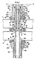
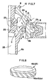
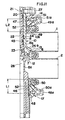
- Fig. 1 is an axial cross section of the lower half below the line a - a of a double sealed valve according to the invention;
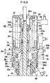
- Fig. 2 is an axial cross section of the upper half above the line a - a of the valve;
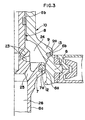
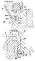
- Fig. 3 is an enlarged fragmentary view in axial cross section of the valve fully closed;
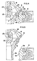
- Fig. 4 is an enlarged fragmentary view in axial cross section of the valve transferring from the fully closed state to an open state;
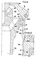
- Fig. 5 is an enlarged fragmentary view in axial cross section of the valve fully opened;
- Fig. 6 is an enlarged fragmentary view in axial cross section of the valve partially opened with the first valve plug slightly open and the second valve plug closed;
- Fig. 7 is an enlarged fragmentary view in axial cross section of the valve partially opened with the second valve plug slightly open and the first valve plug closed;
- Fig. 8 is an enlarged perspective view of a ring in the valve for forming a spiral liquid flow;
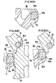
- Fig. 9(A) is an enlarged fragmentary view in axial cross section of the valve, showing the primary annular packing member of the first valve plug opened;
- Fig. 9(B) is an enlarged fragmentary view in axial cross section of the valve fully closed, showing the primary annular packing member of the first valve plug closed;
- Fig. 9(C) is an enlarged fragmentary view in axial cross section of the valve still closed, showing a top edge of the primary annular packing member engaging with the inner conical surface of the second valve plug;
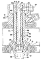
- Fig. 10 is an enlarged partial view in axial cross section of the valve, showing the annular passage for washing liquid defined between the first and second valve stems;
- Fig. 11 is a partial view in axial cross section of the valve, showing the annular passages for washing liquid each defined between the outer periphery of one of the valve stems and the inner periphery of the associated annular member;
- Fig. 12(A) is an enlarged fragmentary view in axial cross section of the valve, showing the clearance between the second valve plug and the valve seat;
- Fig. 12(B) is an enlarged fragmentary view in axial cross section of the valve, showing the clearance between the first valve plug and the valve seat;
- Fig. 13 is an enlarged fragmentary view in axial cross section of the valve, showing the valve plugs and seat having conical surfaces for defining the clearances between them.
-
- With reference to Figs. 1 and 2, the double sealed valve is circular in cross section and has a vertical axis. An upper passage 1 and a
lower passage 2 extend horizontally either in parallel to or across each other. Thepassages 1 and 2 are interconnected by a communicating passage 3, which is defined by avalve seat 6. The upper passage 1 has atop opening 4 formed through its wall. Thelower passage 2 has abottom opening 5 formed through its wall. The communicating passage 3 and theopenings passages 1 and 2. - A
first valve stem 8 is circular in cross section and coaxial with the vertical axis. Thefirst stem 8 extends through theopenings first stem 8 integrally includes a middlecylindrical stem part 8b, which extends through thetop opening 4, and a lowercylindrical stem part 8c, which extends through thebottom opening 5. Formed between thestem parts first valve plug 7, which is integral and coaxial with them. Theplug 7 can engage with the inner periphery of thevalve seat 6. Thefirst stem 8 also includes an uppersolid stem part 8a normally in coaxial screwed engagement with the top of themiddle stem part 8b (in Figs. 1 and 2, thestem parts - A cylindrical second valve stem 10 coaxially surrounds part of the
upper stem part 8a of thefirst valve stem 8 and themiddle stem part 8b. Thissecond stem 10 includes anupper stem part 10a and a lower stem part 10b in coaxial screwed engagement with each other. The lower stem part 10b has asecond valve plug 9 formed integrally at its bottom. Thesecond stem 10 is urged downward by a first coil spring 11, as stated later, so that thesecond plug 9 compressively engages with an upper surface of thevalve seat 6 and is positioned over thefirst valve plug 7. Theplugs seat 6 and the bottom of themiddle stem part 8b define anannular space 24. - As apparent from all Figs. 1 - 13, the
first valve plug 7 has anannular groove 7a formed in its outer periphery. Thegroove 7a holds a primaryannular packing member 12 for tight but slidable contact with an innerperipheral surface 6a of thevalve seat 6. Thesecond valve plug 9 has anannular groove 9a formed in its bottom. Thegroove 9a holds a secondaryannular packing member 13 for compressive contact with the upperconical surface 6b of theseat 6. Provided at thetop opening 4 of the upper passage 1 is an upperannular member 14, through which the lower stem part 10b of thesecond valve stem 10 is guided slidably. The upperannular member 14 includes the root 15a of ayoke 15. The root 15a has a packingmember 16 on its bottom for tight but slidable engagement with the lower stem part 10b. Provided at thebottom opening 5 of thelower passage 2 is a lowerannular member 17, through which thelower stem part 8c of thefirst valve stem 8 is guided slidably. The lowerannular member 17 includes the thick root 18a of asleeve 18. The root 18a has a packingmember 19 on its top for tight but slidable engagement with thelower stem part 8c. - As best shown in Fig. 10, the
middle stem part 8b of thefirst valve stem 8 has anaxial bore 22 formed in it. Themiddle stem part 8b also has an upper communicatinghole 21 and a number oflower orifices 23. Thehole 21 andorifices 23 are formed through the cylindrical wall of thestem part 8b and communicate with theinside passage 22. Some of theorifices 23 extend radially and the others extend at an angle with them. The lower stem part 10b of thesecond valve stem 10 has asupply port 20 formed through its cylindrical wall, which communicates with thehole 21 of thefirst valve stem 8 when thesecond valve plug 9 engages with thevalve seat 6. Fitted to theport 20 is anozzle 27 for connection with a hose (not shown) for supplying a washing liquid. Thenozzle 27 extends through thewindow 15b in theyoke 15. A washing liquid is supplied through the hose, thenozzle 27 and thesupply port 20. Part of the liquid is introduced through thehole 21 into the inside passage or bore 22 and discharged through theorifices 23. - An
annular passage 44 is defined between the outer periphery of themiddle stem part 8b of thefirst valve stem 8 and the inner periphery of the lower stem part 10b of thesecond valve stem 10. The other part of the washing liquid supplied through thesupply port 20 is introduced positively into theannular passage 44 and discharged at the bottom of themiddle stem part 8b. Theannular passage 44 includes atop part 44a, which has a little larger diameter to introduce the liquid from theport 20 effectively into the communicatinghole 21 and theannular passage 44. Fitted to the outer periphery of themiddle stem part 8b are two ormore rings 45 of fluororesin at upper and lower positions in theannular passage 44. As shown in Fig. 8, eachring 45 hasspiral grooves 45a formed at circumferentially regular intervals in its outer periphery to form into a spiral or helical flow the liquid introduced into theannular passage 44. - For example, 70 % of the washing liquid supplied through the
supply port 20 flows through the communicatinghole 21 of into the axialinside passage 22, while 30 % flows through theannular passage part 44a into theannular passage 44. The liquid in theinside passage 22 is ejected through thebottom orifices 23 into theannular space 24. The ejected liquid washes the inside of thespace 24, which includes the inner periphery of thevalve seat 6 and the inner surfaces of the valve plugs 7 and 9. Then, the liquid is discharged through theholes 25 formed in thefirst valve stem 8 and through thebore 26 in thelower stem part 8c to the outside. On the other hand, the liquid in theannular passage 44 flows through thespiral grooves 45a of therings 45, where it is formed into a spiral flow. The spiral flow completely washes the inside of theannular passage 44 and is discharged through theannular space 24, theholes 25 and thebore 26 to the outside. - Thus, by supplying a washing liquid through the
supply port 20, it is possible to wash the inner periphery of thevalve seat 6 and the inner surfaces of the valve plugs 7 and 9. At the same time, it is possible to automatically and completely wash the clearance for sliding between the outer periphery of themiddle stem part 8b of thefirst valve stem 8 and the inner periphery of the lower stem part 10b of thesecond valve stem 10. The washing liquid introduced into theannular passage 44 is formed into a spiral flow through therings 45. The spiral flow can more effectively wash the interior of thepassage 44. - With reference to Figs. 1 and 11, a lower
annular passage 46 is defined between the outer periphery of thelower stem part 8c of thefirst valve stem 8 which extends downward from thelower passage 2 and the inner periphery of the lowerannular member 17, which guides this stem part. Another upperannular passage 47 is defined between the outer periphery of the lower stem part 10b of thesecond valve stem 10 which extends upward from the upper passage 1 and the inner periphery of the upperannular member 14, which guides this stem part. Thepassages stems upper passages supply ports ports supply ports discharge ports supply ports nozzles 48a and 49a respectively for connection with hoses (not shown) for supplying a washing liquid. Fitted to thedischarge ports nozzles - As stated above, the lower and upper
annular passages first stem 8 in a lower position, where thefirst valve plug 7 is closed. Fig. 5 shows both stems 8 and 10 in their upper limit positions, where bothplugs annular member 14 and is exposed to the air. Fig. 6 shows both stems 8 and 10 in their lower limit positions, where thefirst plug 7 is open and thesecond plug 9 is closed, and where a bottom portion of thelower stem part 8c protrudes below the lowerannular member 17 and is exposed to the air. When thefirst stem 8 moves from its lower limit position to its upper limit position, its exposed bottom portion does not enter thelower passage 2. When thesecond stem 10 moves from its upper limit position to its lower limit position, its exposed top portion does not enter the upper passage 1. Thus, since the overall strokes of the first and second stems 8 and 10 are covered by the lower and upperannular passages annular members stems passages 2 and 1 respectively. In addition, the portions of thestems annular passages ports - As shown in Fig. 11, the
annular members ring 52 of fluororesin, which is positioned in the associatedannular passage ring 52 hasspiral grooves 52a formed at circumferentially regular intervals in its outer periphery to form into a spiral flow the washing liquid introduced into thepassage - In order to wash the
lower stem part 8c of thefirst valve stem 8 which extends downward from thelower passage 2, as shown in Fig. 11, a pressurized washing liquid is supplied through thesupply port 48. The liquid sufficiently washes the outer periphery of thestem part 8c while flowing through the lowerannular passage 46. Then, the liquid is discharged through thedischarge port 50. The liquid flowing through the lowerannular passage 46 is formed into a spiral flow through thespiral grooves 52a of thelower ring 52. The spiral flow can effectively wash the outer periphery of thestem part 8c. Likewise, to wash thesecond valve stem 10, a pressurized washing liquid is supplied through thesupply port 49. The liquid sufficiently washes the outer periphery of the lower stem part 10b while flowing through the upperannular passage 47. Then, the liquid is discharged through thedischarge port 51. The liquid is formed into a spiral flow through theupper ring 52. The spiral flow can effectively wash the outer periphery of the stem part 10b. Since thedischarge ports supply ports annular passages discharge ports - With reference to Fig. 2, a first
valve drive mechanism 28 for operating the valve plugs 7 and 9 comprises an air cylinder, which includes a fixedcylinder 30 and apiston 29 for reciprocation in thecylinder 30. Thepiston 29 is fixed to the uppersolid stem part 8a as the piston rod. The first compression spring 11 is interposed between thepiston 29 and theupper stem part 10a of thesecond valve stem 10. The first spring 11 urges thefirst valve stem 8 upward and thesecond valve stem 10 downward. In thecylinder 30, anannular spring bearing 31 is placed at the top of the cylinder around thepiston rod 8a. Asecond compression spring 32 and astopper 33 are interposed between the bearing 31 andpiston 29. Thesecond spring 32 has a larger force than the first spring 11. Thestopper 33 is fixed to thepiston rod 8a, and telescopically engages with thespring bearing 31 to limit the extension of thesecond spring 32 to a certain range. A stroke setting ring R is fitted around therod 8a between thestopper 33 and thetop wall 30c of thecylinder 30. Thespring bearing 31 includes a ringlike body 31o, which bears one end of thesecond spring 32, and a lowercylindrical part 31a formed coaxially and integrally with the body 31o. Thestopper 33 is fixed in position around thepiston rod 8a. Thestopper 33 includes an upper cylindrical part 33a in slidable engagement with thecylindrical bearing part 31a. Thecylindrical parts 31a and 33a haveend flanges 31b and 33b respectively for mutual engagement to interconnect thespring bearing 31 andstopper 33. Normally as shown in Fig. 2, the urging force of thesecond spring 32 engages theflanges 31b and 33b with each other to keep thespring bearing 31 andstopper 33 extended to the full extent. This limits further extension of thesecond spring 32. - The
cylinder 30 hasports lower chambers piston 29. - As stated above, the first spring 11 urges the
first valve stem 8 upward and thesecond valve stem 10 downward. When no pressurized air is supplied to either of the upper andlower chambers first valve plug 7 engages through itsprimary packing member 12 with the innerperipheral surface 6a of thevalve seat 6 while thesecond valve plug 9 engages through itssecondary packing member 13 with theupper seat surface 6b. If pressurized air is supplied through theport 35 to thelower chamber 30b of thecylinder 30, thepiston 29 moves upward together with thefirst valve stem 8 against the compressive force of thesecond spring 32. This retracts the cylindrical part 33a of thestopper 33 into thecylindrical part 31a of thespring bearing 31. While thefirst stem 8 is moving upward, as shown in Fig. 4, the top of thefirst valve plug 7 contacts with the bottom of the inner periphery of thesecond valve plug 9. Thefirst stem 8 keeps moving up, lifting the mutually contactingplugs valve seat 6. When the stroke setting ring R contacts with the cylindertop wall 30c, thepiston 29 reaches its upper limit position, so that the valve is fully open, as shown in Fig. 5, with bothplugs - If the air in the
lower chamber 30b of thecylinder 30 is discharged when the valve is fully open, the force of thesecond spring 32 moves thepiston 29 downward while thespring bearing 31 is pressed on the cylindertop wall 30c. This lowers the valve stems 8 and 10, so that the valve plugs 7 and 9 return to the fully closed state shown in Fig. 3. The ring R sets or adjusts the stroke Sa (Fig. 2) of thepiston 29 between the fully closed position (Fig. 3) and the fully open position (Fig. 5). - If pressurized air is supplied through the
port 34 to theupper chamber 30a of thecylinder 30 when the valve is fully closed as shown in Figs. 1 and 2, the pressure rise in theupper chamber 30a lowers thepiston 29 with thefirst valve stem 8 against the compressive force of the first spring 11, since thestopper 33 limits the extension of thesecond spring 32. This slides theprimary packing member 12 of thefirst valve plug 7 downward on the innerperipheral surface 6a of thevalve seat 6. Thepiston 29 andfirst stem 8 stop moving down when the piston contacts with the top of asecond cylinder 37, which is explained later. In this lower limit position of thefirst stem 8, thefirst plug 7 has left theseat surface 6a and is slightly open, while thesecond plug 9 is still closed, so that the valve is partially open as shown in Fig. 6. It is thus possible to open only thefirst plug 7 by lowering thefirst stem 8 solely or alone with pressurized air supplied to theupper chamber 30a. Thefirst stem 8 can reciprocate with thepiston 29 within the stroke Sb (Fig. 2) independently from thesecond stem 10. - Positioned under the first
valve drive mechanism 28 is a second valvestem drive mechanism 36, which has an air cylinder. Thisdrive mechanism 36 includes thesecond cylinder 37, which is connected to the bottom of the fixedcylinder 30 of thefirst drive 28. Thedrive mechanism 36 also includes asecond piston 38, which is fitted slidably around theupper stem part 10a for reciprocation within a specified stroke in thesecond cylinder 37. Thesecond piston 38 is urged into its lower limit position by athird compression spring 39. Thesecond piston 38 defines alower chamber 37a and anupper chamber 37b on its both sides in thesecond cylinder 37. Theupper chamber 37b communicates with thelower chamber 30b of the fixedcylinder 30. Thedrive mechanism 36 has aport 40 for supplying air to and discharging air from thelower chamber 37a. - The downward movement of the
second piston 38 is limited by astopper 41, which is formed on the bottom wall of thesecond cylinder 37. The upward movement of thesecond piston 38 is limited by astopper 42, which is formed on the top of thesecond cylinder 37. Thesecond piston 38 can reciprocate between thestoppers upper stopper 42 and the outerperipheral part 38a of thesecond piston 38 as positioned on thelower stopper 41. Theupper stem part 10a of thesecond valve stem 10 has astopper 43 formed on it above thesecond piston 38. The stroke S1 is longer than the axial play S2 defined between thissecond stopper 43 and thecentral part 38b of thesecond piston 38 when thesecond stem 10 and thesecond piston 38 are in their lower limit positions (Fig. 2). The upward movement of thesecond piston 38 by the stroke S1 lifts thesecond stem 10 against the force of the first spring 11 by the difference (S1 minus S2) between the stroke S1 and play S2. It is thus possible to make the compressive force of thesecond spring 32 act securely on thesecond stem 10 by defining between thecentral part 38b of thesecond piston 38, which is urged into the lower limit position by thethird spring 39, and thesecond stopper 43 on thesecond stem 10, which is urged into the lower limit position by thesecond spring 32, the axial play S2 shorter than the stroke S1 of thesecond piston 38. - If pressurized air is supplied through the
port 40 to thelower chamber 37a of thesecond cylinder 37 when thesecond piston 38 is kept in its lower limit position shown in Fig. 2, thissecond piston 38 starts to move upward. Until thecentral part 38b of thesecond piston 38 contacts with thesecond stopper 43 on thesecond valve stem 10, thissecond stem 10 is kept in its lower limit position, where thesecond valve plug 9 is closed. After thepiston part 38b contacts with thesecond stopper 43, the upward movement of thesecond piston 38 lifts thesecond stem 10. Thesecond piston 38 keeps moving up until itsperipheral part 38a contacts with theupper stopper 42. In the upper limit position of thesecond stem 10, thesecond plug 9 is slightly open, while thefirst plug 7 is still closed, so that the valve is partially open as shown in Fig. 7. If the air in thechamber 37a is discharged, thesecond piston 38 is lowered by thethird spring 39 until it contacts with thelower stopper 41, while thesecond stem 10 is lowered by thesecond spring 32 until thesecond plug 9 is closed. - The
first valve plug 7 and the primaryannular packing member 12 fitted to it are explained below with reference to Figs. 9(A) - 9(C). - As shown in Fig. 9(A), the primary
annular packing member 12 includes an inner part 12a, which is fitted in theannular groove 7a of thefirst valve plug 7, and anouter part 12b, which protrudes from thegroove 7a. The inner part 12a is sufficiently (8 - 10 times) larger than theouter part 12b in axially cross-sectional area taken radially. Fig. 9(B) shows the valve in the fully closed state, in which the packingmember 12 engages compressively with the innerperipheral surface 6a of thevalve seat 6 and is compressed between theseat 6 andplug 7. - The ratio of the volume of the outer part to the volume of the inner part is relational to the dilatation of the outer part due to a pressure fluctuation and/or a temperature rise of the liquid flowing through the valve when the valve is open. The larger the volume of the inner part is in relation to that of the outer part, the smaller the dilatation of the outer part is. It is therefore possible to lower the dilatation of the
outer part 12b of theprimary packing member 12 by making the inner part 12a sufficiently larger in cross section than theouter part 12b, as stated above. Consequently, when thefirst valve plug 7 opening as shown in Fig. 5 moves downward and transfers to the closed state shown in Figs. 3 and 9(B), the dilatation of theouter part 12b due to a pressure fluctuation and/or a temperature rise of the liquid flowing through the valve is limited to a value as low as possible. This reduces as much as possible the shear force acting on theouter part 12b when theprimary packing member 12 comes into engagement with the innerperipheral surface 6a of theseat 6. As a result, theprimary packing member 12 is prevented from being damaged or broken. - Fig. 9(C) shows in cross section the primary
annular packing member 12 when thefirst valve plug 7 which was closed moves upward, lifting thesecond valve plug 9, and bothplugs valve seat 6 so that the valve gets into the fully opened state. The upward movement of thefirst valve stem 8 brings the top 7b of thefirst plug 7 into contact with a lower part of the innerconical surface 9b of thesecond plug 9, which expands or diverges downward. As a result, the top edge of theouter part 12b of theprimary packing member 12 engages with theconical surface 9b just below the plug top 7b. Thus, when the valve is fully open, the top edge of theouter part 12b engages with theconical surface 9b, so that thesurface 9b partially restrains theouter part 12b. This restrains theouter part 12 from swelling due to a pressure fluctuation and/or a temperature rise of the liquid flowing through the valve. If theouter part 12b is heated or pressurized (compressed) by the liquid when its top edge is in engagement with theconical surface 9b, as shown by solid lines in Fig. 9(C), the edge deforms upward along thesurface 9b so as to be less restrained. It is consequently possible to prevent the overallouter part 12b from radially swelling and deforming as shown by the two-dot chain line in Fig. 9(C). - As stated above, the inner part 12a of the primary
annular packing member 12, which is fitted in thegroove 7a, is sufficiently larger in cross section than theouter part 12b. As also stated, the top edge of theouter part 12b engages with the lower part of the innerconical surface 9b of thesecond valve plug 9 when the valve is fully open. This reduces as much as possible the shear force acting on theouter part 12b when thefirst valve plug 7 transfers from the fully open state to a closing action. It is consequently possible to improve the durability of the packingmember 12. - The primary
annular packing member 12 of thefirst valve plug 7 is made of rubber in which a required amount of fluororesin is mixed. This can reduce the sliding frictional resistance of theprimary packing member 12 and improve its durability. The innerperipheral surface 6a of thevalve seat 6 is covered by a coating or lining layer of fluororesin to improve the durability of thesurface 6a. - Structural features of the valve plugs 7 and 9 and the
valve seat 6 are explained below with reference to Figs. 12(A), 12(B) and 13. - When the valve is partially open, as shown in Fig. 12(A), with the
second valve plug 9 slightly open, a slight clearance Q1 is defined between thesecond plug 9 and thevalve seat 6 over the required opening stroke L1 of thesecond plug 9. Specifically, thesecond plug 9 has an inclinedcircumferential surface 9a, which faces the upperconical surface 6b of thevalve seat 6. Thesecond plug 9 also has an annular bottom 54 protruding over a required length below theinclined surface 9a. Theseat 6 has an innerannular recess 55 formed below theconical surface 6b, which the plug bottom 54 can enter. The clearance Q1 is defined between the outerperipheral surface 54a of the plug bottom 54 and thecircumferential surface 55a of theseat recess 55 nearly constantly over the opening stroke L1 of thesecond plug 9. - If the valve is partially open with the
first valve plug 7 closed and thesecond valve plug 9 open slightly as shown in Fig. 12(A) while, for example, a washing liquid and a drink are flowing through the upper passage 1 andlower passage 2, respectively, and if the stroke of thesecond valve stem 10 is set properly, it is assumed that thesecond plug 9 is positioned as shown by solid lines in Fig. 12(A). Even if a minus error occurs in the stroke of thesecond stem 10, so that thesecond plug 9 is positioned above the proper position, as shown by the dashed line in Fig. 12(A), or if a plus error occurs in the stroke, so that thesecond plug 9 is positioned below the proper position, no pressure is applied to the space in the valve, which is theannular chamber 24, since the clearance Q1 is nearly constant over the stroke L1, as apparent from Fig. 12(A), so that the quantity of the liquid flowing in through the clearance Q1 is nearly constant. - As shown in Fig. 12(B), a slight clearance Q2 is defined between the
first valve plug 7 andvalve seat 6 over the required opening stroke L2 of thefirst plug 7 when thefirst plug 7 is open. Specifically, theseat 6 has a bottom 57 of a smaller inner diameter and an innerannular groove 56 formed between the bottom 57 andperipheral surface 6a. The clearance Q2, which is nearly constant over the stroke L2, is defined between the inner peripheral surface 57a of the bottom 57 and the outerperipheral surface 58 of the bottom of thefirst plug 7. - If the valve is partially open with the
second valve plug 9 closed and thefirst valve plug 7 open slightly as shown in Fig. 12(B) while, for example, a washing liquid and a drink are flowing through thepassages 2 and 1, respectively, and if the stroke of thefirst valve stem 8 is set properly, it is assumed that thefirst plug 7 is positioned as shown by solid lines in Fig. 12(B). Even if an error occurs in the stroke of thefirst stem 8, so that thesecond plug 9 is positioned above or below the proper position, as shown by dashed or two-dot chain lines in Fig. 12(B), no pressure is applied to theannular chamber 24 because the clearance Q2 is nearly constant over the stroke L2, as apparent from Fig. 12(B), so that the quantity of the liquid flowing in through the clearance Q2 is nearly constant. - The peripheral or
circumferential surfaces second valve plug 9 andvalve seat 6, which define the clearance Q1, might be cylindrical in parallel to each other. If these surfaces were cylindrical, however, they might contact with each other. The surfaces should therefore be gently conical. Likewise, theperipheral surfaces 58 and 57a of thefirst valve plug 7 and theseat 6, which define the clearance Q2 should be gently conical. Fig. 13 shows thesurfaces - Thus, even if an error occurs in the stroke of the
second valve stem 10 when, for example, a washing liquid and a drink are flowing through the upper passage 1 andlower passage 2, respectively, and the valve is partially open with thefirst valve plug 7 closed and thesecond valve plug 9 open slightly for washing by allowing a washing liquid to flow from the upper passage 1 into the space in the valve, a slight clearance is defined, no pressure is applied to the space in the valve, because a slight clearance is defined between thesecond plug 9 andseat 6 over the required opening stroke of thesecond plug 9 when thesecond plug 9 opens, so that the quantity of the liquid flowing in through the clearance is nearly constant. Therefore, no washing liquid is mixed into the drink, so that the drink can be kept safe. If the peripheral surfaces of thesecond plug 9 andseat 6 which define the clearance are conical, they do not contact with each other, so that the open state of the valve can be maintained securely. - When no pressurized air is supplied to the
lower chamber 30b of the fixedcylinder 30 of the firstvalve drive mechanism 28, the double sealed valve is fully closed, as shown in Figs. 1 - 3, with both valve plugs 7 and 9 closed. Specifically, in such a condition, thefirst plug 7 engages through the primaryannular packing member 12 tightly but slidably with the innerperipheral surface 6a of thevalve seat 6, while the first spring 11 urges thesecond valve stem 10 downward so that thesecond plug 9 engages through the secondaryannular packing member 13 compressively with the upperconical surface 6b of theseat 6. Consequently, the communicating passage 3 between the upper passage 1 andlower passage 2 is sealed doubly with thefirst plug 7 adjacent to thelower passage 2 and thesecond plug 9 adjacent to the upper passage 1. Therefore, the liquids flowing through thepassages 1 and 2, respectively, are prevented from mixing with each other. - If pressurized air is supplied to the
lower chamber 30b of the fixedcylinder 30, thefirst valve plug 7 moves upward, as shown in Fig. 4, lifting thesecond valve plug 9. Theplugs valve seat 6, as shown in Fig. 5, so that the valve is fully open. This opens the communicating passage 3, through which the upper passage 1 andlower passage 2 can communicate with each other. - When a highly viscous liquid or another liquid difficult to wash out is used, one of the valve plugs 7 and 9 is closed and the other is opened slightly. While the packing member of the open valve plug is washed with a washing liquid, the liquid is discharged. For example, when a highly viscous drink and a washing liquid flow through the upper passage 1 and
lower passage 2, respectively, pressurized air is supplied to theupper chamber 30a of the fixedcylinder 30. The pressure rise in theupper chamber 30a lowers thepiston 29 together with thesecond spring 32, the extension of which is limited. Consequently, thefirst valve stem 8 and thefirst plug 7 move downward with the primaryannular packing member 12 sliding downward on the innerperipheral surface 6a of thevalve seat 6. When thepiston 29 has reached its bottom position, the valve is partially open, as shown in Fig. 6, with thefirst plug 7 having left thesurface 6a to be open slightly and thesecond plug 9 still closed. As shown by arrows in Fig. 6, a washing liquid flows from thelower passage 2, through the clearance between thefirst plug 7 andseat 6 and into theannular chamber 24, which is defined by theplugs seat 6 and themiddle stem part 8b of thefirst valve stem 8. The flowing liquid washes theprimary packing member 12, the surfaces of thefirst plug 7 near themember 12, and the inside of thechamber 24. Then, the liquid is discharged through thebore 26 in thelower stem part 8c to the outside. - When a highly viscous drink and a washing liquid flow through the
lower passage 2 and upper passage 1, respectively, pressurized air is supplied to thelower chamber 37a of thesecond cylinder 37 of the secondvalve drive mechanism 36 to lift thesecond piston 38. While moving up, thesecond piston 38 lifts thesecond valve stem 10 by the specified stroke (S1 - S2). When thesecond piston 38 has reached its top position, the valve is partially open, as shown in Fig. 7, with only thesecond valve plug 9 slightly open. As shown by arrows in Fig. 7, a washing liquid flows from the upper passage 1, between thesecond plug 9 and the upperconical surface 6b of thevalve seat 6, and into theannular chamber 24, in which it circles or flows round. As a result, the liquid washes the secondaryannular packing member 13, the surfaces of thesecond plug 9 near themember 13, and the inside of thechamber 24. Thereafter, the liquid is discharged through thebore 26 in thelower stem part 8c of thefirst valve stem 8 to the outside. - Since only one
piston 29 is provided in the fixedcylinder 30, and it is fixed to the piston rod, the firstvalve drive mechanism 28 needs only one air-tight seal. Therefore, the mechanism is simple in structure and easy to make. In addition, the operation of thepiston 29 cannot be out of order, and accordingly the valve operation cannot be wrong. - As stated already, the second
valve drive mechanism 36 is provided under the firstvalve drive mechanism 28. If pressurized air is supplied to thelower chamber 37a of thesecond cylinder 37 when thesecond piston 38 is kept in its lower limit position, the upward movement of thesecond piston 38 lifts thesecond valve stem 10, so that the valve is partially open with only thesecond valve plug 9 open. If the air in thechamber 37a is discharged, thethird spring 39 lowers thesecond piston 38, so that the first spring 11 lowers thesecond stem 10 to close thesecond plug 9. Thesecond cylinder 37 is so formed under the fixedcylinder 30 as to communicate with the fixedcylinder 30, without interposing a partition as was the case with the conventional apparatus. Therefore, the apparatus of the present invention can be simple and compact in structure, and is accordingly easy to make.
Claims (14)
- A double sealed valve comprising:characterised in thatan annular valve seat (6) in a communicating passage (3) formed between an upper passage (1) and a lower passage (2);a first vertical valve stem (8) and a second vertical valve stem (10), which is hollow, slidably surrounds said first valve stem (8) and is urged downward by a first spring (11);said first valve stem (8) having a first circular valve plug (7), which holds a primary annular packing member (12) for slidable engagement with an inner peripheral surface (6a) of said valve seat (6);said second valve stem (10) having a second circular valve plug (9), which holds a secondary annular packing member (13) for compressive engagement with an upper surface (6b) of said valve seat (6); anda valve drive mechanism (28) connected to said first valve stem (8) so as to move said first valve stem (8) and said first valve plug (7) upwardly for opening said valve, followed by said second valve stem (10) and said second valve plug (9) ;said first valve plug (7) having an annular groove (7a), said primary packing member (12) consisting of an inner part (12a), which is fitted in said groove (7a), and an outer part (12b), which protrudes from said groove (7a) ;
said inner part (12a) of said primary packing member (12) is sufficiently larger than said outer part (12b) thereof in axially sectional area taken radially, and said outer part (12b) of said primary packing member (12) has a top edge engaging with the bottom of an inner conical surface (9b) diverging downward of said second valve plug (9) when said valve opens, so as to restrain said outer part (12b) from being dilated by pressure fluctuation and/or temperature change of liquid when said valve opens. - A double sealed valve according to claim 1, wherein said primary annular packing member (12) is made of rubber into which a required amount of fluororesin is mixed.
- A double sealed valve according to claim 1 or 2, wherein said inner peripheral surface (6a) of the valve seat (6) is coated or lined with fluororesin.
- A double sealed valve according to claim 1, wherein said valve drive mechanism (28) comprises an air cylinder which includes a fixed vertical cylinder (30) and a piston (29) for reciprocation in said cylinder, which piston (29) is fixed to said first valve stem (8) as the piston rod, said piston (29) defining an upper chamber (30a) and a lower chamber (30b) in said fixed cylinder (30), and said fixed cylinder (30) having ports (34) and (35) for supplying air to and discharging air from said upper and lower chambers (30a) and (30b), respectively;
said first spring (11) being interposed between said piston (29) and said second valve stem (10);
a spring bearing (31) placed at the top of the space in said fixed cylinder (30);
a second spring (32) interposed between said bearing (31) and said piston (29), said second spring (32) having a larger force than said first spring (11); and
a stopper (33) interposed between said bearing (31) and said piston (29), said stopper (33) being fixed to said piston rod and connected in vertically telescopic relationship with said bearing (31) to limit the extension of said second spring (32) to a certain range. - A double sealed valve according to claim 4, further comprising a valve stem drive mechanism (36) under said valve drive mechanism (28), said valve stem drive mechanism (36) comprising an air cylinder, which includes a second vertical cylinder (37) formed under said fixed cylinder (30) and communicating with the bottom of said fixed cylinder (30), a second piston (38) slidably surrounding said second valve stem (10) for reciprocation by a specified stroke (S1) in said second cylinder (37), and a third spring (39) urging said second piston (38) into a lower limit position, said second piston (38) defining a second lower chamber (37a) thereunder in said second cylinder (37), said second cylinder (37) having a port (40) for supplying air to and discharging air from said second lower chamber (37a), whereby the upward movement of said second piston (38) by supplying air to said second lower chamber (37a) lifts said second valve stem (10) against the urging force of said first spring (11) to open said second valve plug (9).
- A double sealed valve according to Claim 5, wherein said second piston (38) includes a central part (38b), said second valve stem (10) having a second stopper (43) fixed thereto and positioned above said second piston (38), said central part (38b) and said second stopper (43) being spaced axially by a play (S2) when said second piston (38) is urged into the lower limit position by said third spring (39) and when said second valve stem (10) and said second valve plug (9) are urged into the closed position by said first spring (11), the play (S2) being shorter than the stroke (S1) of said second piston (38) so that the stroke of said second valve stem (10) is the stroke (S1) of said second piston (38) minus the play (S2) (S1 - S2).
- A double sealed valve according to claim 1, wherein
said second valve stem (10) has a supply port (20) formed through the tubular wall thereof;
said first valve stem (8) having an inside passage (22) and orifices (23), which interconnect a bottom part of said inside passage (22) and the outside of said first valve stem (8);
whereby a washing liquid can be supplied through said supply port (20) and said inside passage (22) and ejected out through said orifices (23);
the outer peripheral surface of said first valve stem (8) and the inner peripheral surface of said second valve stem (10) defining an annular passage (44) therebetween for positively introducing and discharging from the bottom of said second valve stem (10) a part of the liquid supplied through said supply port (20). - A double sealed valve according to claim 7, further comprising a ring (45) in said annular passage (44) between said first and second valve stems (8) and (10), said ring (45) having a number of spiral grooves (45a) formed in the outer peripheral surface thereof for forming into a spiral flow the liquid introduced into said annular passage (44).
- A double sealed valve according to claim 1, wherein said second valve plug (9) and said valve seat (6) define a slight clearance (Q1) therebetween over the required opening stroke (L1) of said second valve plug (9) when said second valve plug (9) opens.
- A double sealed valve according to claim 9, wherein the surfaces of said second valve plug (9) and said valve seat (6) which define the slight clearance (Q1) are conical.
- A double sealed valve according to Claim 9, wherein said first valve plug (7) and said valve seat (6) define a second slight clearance (Q2) therebetween over the required opening stroke (L2) of said first valve plug (7) when said first valve plug (7) opens.
- A double sealed valve according to Claim 11, wherein the surfaces of said first valve plug (7) and said valve seat (6) which define the second slight clearance (Q2) are gently conical.
- A double sealed valve according to claim 1, further comprising:an upper annular member (14) for slidably guiding the outer peripheral surface of the upper part of said second valve stem (10) which extends upward from said upper passage (1),said outer peripheral surface of the second valve stem (10) and the inner peripheral surface of said upper annular member (14) defining an upper annular passage (47) therebetween, which is longer than the maximum stroke of said second valve stem (10); anda lower annular member (17) for slidably guiding the outer peripheral surface of the lower part of said first valve stem (8) which extends downward from said lower passage (2);said outer peripheral surface of the first valve stem (8) and the inner peripheral surface of said lower annular member (17) defining a lower annular passage (46) therebetween, which is longer than the maximum stroke of said first valve stem (8);said annular passages (46, 47) having supply ports (48) and (49) respectively of small diameters, which are formed at their bottoms, for supplying washing liquid to said annular passages (46, 47); andsaid annular passages (46, 47) also having discharge ports (50) and (51) respectively of large diameters, which are formed at their tops, for discharging washing liquid from said annular passages (46, 47).
- A double sealed valve according to claim 13, further comprising a ring (52) in each of said annular passages (46, 47), said ring (52) having a number of spiral grooves (52a) formed in the outer peripheral surface thereof for forming into a spiral flow the liquid supplied to the associated annular passage.
Applications Claiming Priority (15)
| Application Number | Priority Date | Filing Date | Title |
|---|---|---|---|
| JP184889/96 | 1996-07-15 | ||
| JP18488896 | 1996-07-15 | ||
| JP18488996 | 1996-07-15 | ||
| JP184887/96 | 1996-07-15 | ||
| JP18488796 | 1996-07-15 | ||
| JP18488896A JP3765619B2 (en) | 1996-07-15 | 1996-07-15 | Double seal valve |
| JP18488696A JP3765618B2 (en) | 1996-07-15 | 1996-07-15 | Double seal valve |
| JP184886/96 | 1996-07-15 | ||
| JP18488696 | 1996-07-15 | ||
| JP18489096 | 1996-07-15 | ||
| JP18489096A JP3765620B2 (en) | 1996-07-15 | 1996-07-15 | Double seal valve |
| JP184890/96 | 1996-07-15 | ||
| JP18488996A JP3761251B2 (en) | 1996-07-15 | 1996-07-15 | Double seal valve |
| JP18488796A JP3795584B2 (en) | 1996-07-15 | 1996-07-15 | Double seal valve |
| JP184888/96 | 1996-07-15 |
Publications (3)
| Publication Number | Publication Date |
|---|---|
| EP0819876A2 EP0819876A2 (en) | 1998-01-21 |
| EP0819876A3 EP0819876A3 (en) | 1998-05-13 |
| EP0819876B1 true EP0819876B1 (en) | 2002-12-11 |
Family
ID=27528879
Family Applications (1)
| Application Number | Title | Priority Date | Filing Date |
|---|---|---|---|
| EP19960115029 Expired - Lifetime EP0819876B1 (en) | 1996-07-15 | 1996-09-19 | Double sealed valve |
Country Status (4)
| Country | Link |
|---|---|
| US (1) | US5904173A (en) |
| EP (1) | EP0819876B1 (en) |
| CN (1) | CN1082639C (en) |
| DE (1) | DE69625344T2 (en) |
Cited By (1)
| Publication number | Priority date | Publication date | Assignee | Title |
|---|---|---|---|---|
| WO2005098287A1 (en) * | 2004-03-29 | 2005-10-20 | Tuchenhagen Gmbh | Double-seat valve |
Families Citing this family (23)
| Publication number | Priority date | Publication date | Assignee | Title |
|---|---|---|---|---|
| DE19548860C1 (en) * | 1995-12-27 | 1997-01-16 | Tetra Laval Holdings & Finance | Shut-off valve |
| ATE226291T1 (en) * | 1997-05-28 | 2002-11-15 | Tetra Laval Holdings & Finance | DOUBLE SEAT VALVE |
| DE19750300A1 (en) * | 1997-11-13 | 1999-06-02 | Alfa Laval Lkm A S | Double seat valve |
| KR100278476B1 (en) * | 1997-12-29 | 2001-01-15 | 윤종용 | Method for cleaning a valve |
| DE19842922A1 (en) * | 1998-09-18 | 2000-03-23 | Rieger Gmbh & Co Kg Geb | Valve, especially double seat valve |
| WO2001002762A1 (en) | 1999-07-02 | 2001-01-11 | Alfa Laval Lkm A/S | Double sealing valve |
| DK1945975T3 (en) | 2005-11-12 | 2009-08-31 | Gea Tuchenhagen Gmbh | Double seat valve |
| US20070215830A1 (en) * | 2006-03-15 | 2007-09-20 | United Dominion Industries, Inc. | Method and apparatus for providing cleanability to a valve |
| DE102006046442A1 (en) * | 2006-09-25 | 2008-03-27 | Gebr. Rieger Gmbh & Co. Kg | Double-seat valve device |
| US7718058B2 (en) | 2007-04-25 | 2010-05-18 | Bio-Rad Laboratories, Inc. | Chromatography column with pack, unpack, and clean-in-place features |
| DE202008003976U1 (en) * | 2008-03-20 | 2008-11-27 | Gea Tuchenhagen Gmbh | Seat-cleaning double-seat valve with a cleaning device for a rod feed-through |
| US8327881B2 (en) * | 2008-09-19 | 2012-12-11 | Spx Corporation | Double seat valve apparatus |
| SE534199C2 (en) * | 2009-10-02 | 2011-05-31 | Alfa Laval Corp Ab | A mix-safe valve comprising a cleaning device and a cleaning arrangement for cleaning a valve outlet space |
| EP2333385B1 (en) | 2009-12-10 | 2017-01-25 | Alfa Laval Corporate AB | Double-seat valve |
| DE102010030299A1 (en) * | 2010-06-21 | 2011-12-22 | Krones Aktiengesellschaft | Device for driving a double seat valve |
| US8579249B2 (en) * | 2010-11-04 | 2013-11-12 | Fisher Controls International Llc | Biasing device for use with actuators of fluid valves |
| DE102011077717B4 (en) | 2011-06-17 | 2015-05-21 | Neumo Gmbh + Co. Kg | Double seat valve device with solid contact |
| DE102011120287B3 (en) * | 2011-12-03 | 2012-11-15 | Gea Tuchenhagen Gmbh | Drive for shifting double seat valve, has drive piston that is moved from closed position to partially open position toward open position, so that valve is operated using seat plate during specific configuration of drive |
| CN104006165B (en) * | 2012-09-21 | 2016-05-11 | 张轶 | Secondary seal stop valve |
| DE102018207522A1 (en) * | 2018-05-15 | 2019-11-21 | Evoguard Gmbh | valve combination |
| CN109253268B (en) * | 2018-11-02 | 2020-05-26 | 李祥庆 | Regulating valve with gear box and using method thereof |
| EP3792527A1 (en) | 2019-09-10 | 2021-03-17 | Alfa Laval Corporate AB | Gasket, fluid flow control valve and method of cleaning such a valve |
| EP4166825A1 (en) * | 2021-10-15 | 2023-04-19 | Alfa Laval Corporate AB | Flow control arrangment and method of cleaning such an arrangement |
Family Cites Families (15)
| Publication number | Priority date | Publication date | Assignee | Title |
|---|---|---|---|---|
| NL191605C (en) * | 1977-11-19 | 1995-10-17 | Holstein & Kappert Maschf | Valve with two valve seats with double seats. |
| SE424357B (en) * | 1979-11-20 | 1982-07-12 | Hakan Jeppsson | VALVE WITH DOUBLE SEALS |
| SE432982B (en) * | 1980-04-24 | 1984-04-30 | Alfa Laval Ab | MIXING SAFETY VALVE |
| US4373545A (en) * | 1981-01-26 | 1983-02-15 | Cherry-Burrell Corporation | Double block and vent valve |
| DE3211692A1 (en) * | 1982-03-30 | 1983-10-06 | Holstein & Kappert Maschf | METHOD FOR CLEANING CAVES IN DOUBLE SEAT VALVES |
| EP0126744B1 (en) * | 1982-11-29 | 1987-03-25 | Bm Digiflow A/S | A stop or switch valve for fluids |
| NL8303437A (en) * | 1983-10-06 | 1985-05-01 | Hoogeveen Appendagefab | VALVE. |
| ATE29568T1 (en) * | 1984-09-12 | 1987-09-15 | Lavrids Knudsen Maskinfab As | DOUBLE SEAT VALVE. |
| US4605035A (en) * | 1984-09-14 | 1986-08-12 | Lavrids Knudsen Maskinefabrik A/S | Double seat valve |
| EP0205627A1 (en) * | 1985-06-11 | 1986-12-30 | OTTO TUCHENHAGEN GmbH & Co. KG | Process for obtaining a leakless double-seat valve with washing of the seats, and device for carrying out the process |
| DE8524858U1 (en) * | 1985-08-30 | 1985-10-10 | Albert Handtmann Armaturenfabrik GmbH & Co KG, 7950 Biberach | Double disk valve |
| DE4118874C2 (en) * | 1991-06-07 | 1995-02-16 | Tuchenhagen Otto Gmbh | Method for cleaning a leak-free switching double-seat valve and valve device for carrying out the method |
| EP0646741B1 (en) * | 1993-09-21 | 1996-09-04 | Apv Rosista Gmbh | Leakproof double seat valve |
| DE4332109C2 (en) * | 1993-09-22 | 1995-07-06 | Tuchenhagen Otto Gmbh | Device for leak-free switching of a double seat valve |
| EP0711940B1 (en) * | 1994-09-20 | 1999-07-21 | TUCHENHAGEN GmbH | Method for a leak-free operation of a double-seat valve, sealing arrangement therefore |
-
1996
- 1996-09-19 EP EP19960115029 patent/EP0819876B1/en not_active Expired - Lifetime
- 1996-09-19 DE DE69625344T patent/DE69625344T2/en not_active Expired - Lifetime
- 1996-11-29 CN CN96120748A patent/CN1082639C/en not_active Expired - Fee Related
-
1997
- 1997-07-10 US US08/890,953 patent/US5904173A/en not_active Expired - Lifetime
Cited By (1)
| Publication number | Priority date | Publication date | Assignee | Title |
|---|---|---|---|---|
| WO2005098287A1 (en) * | 2004-03-29 | 2005-10-20 | Tuchenhagen Gmbh | Double-seat valve |
Also Published As
| Publication number | Publication date |
|---|---|
| DE69625344T2 (en) | 2003-09-18 |
| US5904173A (en) | 1999-05-18 |
| CN1082639C (en) | 2002-04-10 |
| CN1170839A (en) | 1998-01-21 |
| DE69625344D1 (en) | 2003-01-23 |
| HK1007896A1 (en) | 1999-04-30 |
| EP0819876A2 (en) | 1998-01-21 |
| EP0819876A3 (en) | 1998-05-13 |
Similar Documents
| Publication | Publication Date | Title |
|---|---|---|
| EP0819876B1 (en) | Double sealed valve | |
| US4632228A (en) | Cylinder piston device | |
| KR100346034B1 (en) | Manually operated spray device for liquid | |
| JPS6210691B2 (en) | ||
| EP1251282B1 (en) | Vehicle braking system with a gas hydraulic accumulator | |
| EP0357592B1 (en) | Adjustable oleopneumatic support, particularly for office chairs with central column | |
| KR920700779A (en) | Liquid ejector | |
| US20110041807A1 (en) | Damping arrangement for a fuel injector | |
| US6318421B1 (en) | Limit control device for filling a liquid storage tank | |
| US6186163B1 (en) | Double seat valve | |
| JPH0536318B2 (en) | ||
| KR850000832B1 (en) | Control valve for double-acting piston and valve assembly | |
| US7540362B2 (en) | Adjustable-length gas spring | |
| US3294118A (en) | Filling valve for gas lighters | |
| KR100458173B1 (en) | Discharge device for media | |
| US3704695A (en) | Valve construction for variable compression ratio piston | |
| US20070102252A1 (en) | Built-in damper type front fork | |
| JPH03125084A (en) | Safety valve for gas cylinder | |
| DE10245606A1 (en) | Valve arrangement for a pressure flushing system | |
| JPS6219615B2 (en) | ||
| JP3765618B2 (en) | Double seal valve | |
| US4074887A (en) | Power unit for a medical or like stool | |
| US11187335B2 (en) | Fast-switching 2/2-way cartridge valve | |
| US5277577A (en) | One-way valve for fluids | |
| JP3795584B2 (en) | Double seal valve |
Legal Events
| Date | Code | Title | Description |
|---|---|---|---|
| PUAI | Public reference made under article 153(3) epc to a published international application that has entered the european phase |
Free format text: ORIGINAL CODE: 0009012 |
|
| AK | Designated contracting states |
Kind code of ref document: A2 Designated state(s): DE FR IT NL SE |
|
| PUAL | Search report despatched |
Free format text: ORIGINAL CODE: 0009013 |
|
| AK | Designated contracting states |
Kind code of ref document: A3 Designated state(s): DE FR IT NL SE |
|
| 17P | Request for examination filed |
Effective date: 19980915 |
|
| AKX | Designation fees paid |
Free format text: DE FR IT NL SE |
|
| RBV | Designated contracting states (corrected) |
Designated state(s): DE FR IT NL SE |
|
| RBV | Designated contracting states (corrected) |
Designated state(s): DE FR IT NL SE |
|
| 17Q | First examination report despatched |
Effective date: 20010427 |
|
| GRAG | Despatch of communication of intention to grant |
Free format text: ORIGINAL CODE: EPIDOS AGRA |
|
| GRAG | Despatch of communication of intention to grant |
Free format text: ORIGINAL CODE: EPIDOS AGRA |
|
| GRAH | Despatch of communication of intention to grant a patent |
Free format text: ORIGINAL CODE: EPIDOS IGRA |
|
| GRAH | Despatch of communication of intention to grant a patent |
Free format text: ORIGINAL CODE: EPIDOS IGRA |
|
| GRAA | (expected) grant |
Free format text: ORIGINAL CODE: 0009210 |
|
| AK | Designated contracting states |
Kind code of ref document: B1 Designated state(s): DE FR IT NL SE |
|
| REF | Corresponds to: |
Ref document number: 69625344 Country of ref document: DE Date of ref document: 20030123 |
|
| ET | Fr: translation filed | ||
| PGFP | Annual fee paid to national office [announced via postgrant information from national office to epo] |
Ref country code: FR Payment date: 20030915 Year of fee payment: 8 |
|
| PGFP | Annual fee paid to national office [announced via postgrant information from national office to epo] |
Ref country code: SE Payment date: 20030916 Year of fee payment: 8 |
|
| PGFP | Annual fee paid to national office [announced via postgrant information from national office to epo] |
Ref country code: NL Payment date: 20030930 Year of fee payment: 8 |
|
| PLBE | No opposition filed within time limit |
Free format text: ORIGINAL CODE: 0009261 |
|
| STAA | Information on the status of an ep patent application or granted ep patent |
Free format text: STATUS: NO OPPOSITION FILED WITHIN TIME LIMIT |
|
| 26N | No opposition filed |
Effective date: 20030912 |
|
| PG25 | Lapsed in a contracting state [announced via postgrant information from national office to epo] |
Ref country code: SE Free format text: LAPSE BECAUSE OF NON-PAYMENT OF DUE FEES Effective date: 20040920 |
|
| PG25 | Lapsed in a contracting state [announced via postgrant information from national office to epo] |
Ref country code: NL Free format text: LAPSE BECAUSE OF NON-PAYMENT OF DUE FEES Effective date: 20050401 |
|
| EUG | Se: european patent has lapsed | ||
| PG25 | Lapsed in a contracting state [announced via postgrant information from national office to epo] |
Ref country code: FR Free format text: LAPSE BECAUSE OF NON-PAYMENT OF DUE FEES Effective date: 20050531 |
|
| NLV4 | Nl: lapsed or anulled due to non-payment of the annual fee |
Effective date: 20050401 |
|
| REG | Reference to a national code |
Ref country code: FR Ref legal event code: ST |
|
| PG25 | Lapsed in a contracting state [announced via postgrant information from national office to epo] |
Ref country code: IT Free format text: LAPSE BECAUSE OF NON-PAYMENT OF DUE FEES;WARNING: LAPSES OF ITALIAN PATENTS WITH EFFECTIVE DATE BEFORE 2007 MAY HAVE OCCURRED AT ANY TIME BEFORE 2007. THE CORRECT EFFECTIVE DATE MAY BE DIFFERENT FROM THE ONE RECORDED. Effective date: 20050919 |
|
| PGFP | Annual fee paid to national office [announced via postgrant information from national office to epo] |
Ref country code: DE Payment date: 20120917 Year of fee payment: 17 |
|
| REG | Reference to a national code |
Ref country code: DE Ref legal event code: R119 Ref document number: 69625344 Country of ref document: DE Effective date: 20140401 |
|
| PG25 | Lapsed in a contracting state [announced via postgrant information from national office to epo] |
Ref country code: DE Free format text: LAPSE BECAUSE OF NON-PAYMENT OF DUE FEES Effective date: 20140401 |