EP0819654B1 - Mold assembly for glass articles - Google Patents
Mold assembly for glass articles Download PDFInfo
- Publication number
- EP0819654B1 EP0819654B1 EP97111943A EP97111943A EP0819654B1 EP 0819654 B1 EP0819654 B1 EP 0819654B1 EP 97111943 A EP97111943 A EP 97111943A EP 97111943 A EP97111943 A EP 97111943A EP 0819654 B1 EP0819654 B1 EP 0819654B1
- Authority
- EP
- European Patent Office
- Prior art keywords
- mold
- mold holder
- sections
- adjacent
- fins
- Prior art date
- Legal status (The legal status is an assumption and is not a legal conclusion. Google has not performed a legal analysis and makes no representation as to the accuracy of the status listed.)
- Expired - Lifetime
Links
- 239000011521 glass Substances 0.000 title claims abstract description 24
- 238000001816 cooling Methods 0.000 claims abstract description 32
- 238000000465 moulding Methods 0.000 claims abstract description 16
- 239000012530 fluid Substances 0.000 claims abstract description 12
- 238000007496 glass forming Methods 0.000 claims description 5
- 239000012809 cooling fluid Substances 0.000 claims description 4
- 230000004323 axial length Effects 0.000 abstract description 2
- 230000013011 mating Effects 0.000 description 4
- 239000006060 molten glass Substances 0.000 description 3
- 239000002826 coolant Substances 0.000 description 2
- 238000004519 manufacturing process Methods 0.000 description 2
- 238000012545 processing Methods 0.000 description 2
- 230000006978 adaptation Effects 0.000 description 1
- 238000013459 approach Methods 0.000 description 1
- 238000000071 blow moulding Methods 0.000 description 1
- 238000007664 blowing Methods 0.000 description 1
- 238000013461 design Methods 0.000 description 1
- 238000000034 method Methods 0.000 description 1
- 238000012986 modification Methods 0.000 description 1
- 230000004048 modification Effects 0.000 description 1
Images



Classifications
-
- C—CHEMISTRY; METALLURGY
- C03—GLASS; MINERAL OR SLAG WOOL
- C03B—MANUFACTURE, SHAPING, OR SUPPLEMENTARY PROCESSES
- C03B9/00—Blowing glass; Production of hollow glass articles
- C03B9/30—Details of blowing glass; Use of materials for the moulds
- C03B9/38—Means for cooling, heating, or insulating glass-blowing machines or for cooling the glass moulded by the machine
- C03B9/3875—Details thereof relating to the side-wall, body or main part of the moulds
-
- C—CHEMISTRY; METALLURGY
- C03—GLASS; MINERAL OR SLAG WOOL
- C03B—MANUFACTURE, SHAPING, OR SUPPLEMENTARY PROCESSES
- C03B9/00—Blowing glass; Production of hollow glass articles
- C03B9/30—Details of blowing glass; Use of materials for the moulds
- C03B9/34—Glass-blowing moulds not otherwise provided for
- C03B9/353—Mould holders ; Mould opening and closing mechanisms
Definitions
- This invention relates to a mold assembly for use in forming hollow glass articles on a forming machine of the individual section ("I.S.") type. More particularly this invention relates to a mold assembly of the foregoing character that provides positive, indirect cooling of the article being molded in the mold assembly.
- Hollow glass articles such as bottles and jars, when molded by a forming machine of the I.S. type, are molded in two steps.
- a preform of the finished container which is usually called a blank or a parison
- an annular mold made up of a pair of mating blank mold sections.
- the blank mold sections separate and the blank or parison is transferred to another mold station, often called the blow mold station, where it is blown into its final shape by another annular mold that is made up of another mating pair of mold sections.
- the blow mold station often called the blow mold station
- the mating sections of the blow mold are separated, and the container is removed from the forming machine for further processing.
- the glass gob that is formed into a parison in the blank mold of an I.S. machine is sufficiently hot to be capable of being shaped into a blank and, thus, possesses a high level of latent heat. Much of this heat must be removed before the container is removed from the blow mold of the forming machine, however, so that the finished container will be sufficiently rigid to undergo further processing without any further change in its shape. Thus, much heat must be removed from the container being formed, both during the blank molding step and the blow molding step, and unless the heat is removed at a rapid rate, the productivity of the forming machine is unduly limited. The problem of heat removal from the molds of an I.S.
- the surface area of the parison is quite small due to the small diameter of the parison, which limits the rate at which heat can be removed, and the amount of heat to be removed is quite high due to the larger wall thickness of the parison in comparison to the wall thicknesses of a finished container.
- a mold arrangement according to the preamble of claim 1 is known from GB-A-1,122,899.
- the apparatus includes a pair of pivotable mold arms formed with jaws to carry a single annular mold and to distribute the cooling air across the mold.
- No mold assembly including fluid flow passages is provided for being inserted and coupled to the pivotable mold arms.
- a mold cooling apparatus showing a pair of pivotable mold arms for carrying individual cavity as well as multicavity mold equipment is known from EP-A-0,612,699.
- a diffuser plate is provided to distribute cooling flow in a space which extends along the tips of cooling fins of a mold half.
- the mold equipment is not shown to constitute a mold assembly which includes the fluid flow passages for distributing the cooling air over the proper mold.
- the problem to be solved by the invention is to create a mold arrangement having a mold holder which is adapted to distribute cooling fluid for a variety of molds which can be replaced in the glass forming machine.
- the invention is defined in claim 1.
- the mold arrangement includes an annular mold which is made up of a mating pair of mold sections, whose internal surface, when the mold sections are joined end to end, defines the external shape of a glass article to be formed in an internal cavity of such annular mold, either the final shape of a glass article in the case of a blow mold or the shape of a preform of such article in a blank mold.
- the exterior of each of the mold sections is provided with a circumferential plurality of radially projecting, axially extending spaced apart ribs to extend the surface of the mold sections to thereby increase the rate at which latent heat can be removed from the molten glass article within the mold.
- the mold assembly also includes a split mold holder for holding the mold sections of a mold, as heretofore described.
- the mold holder which is suitable for use with a variety of molds, surrounds the mold and directs air or other cooling fluid radially inwardly against the ribs on the exterior of the mold sections from radially open, axially extending flow passages.
- a split, perforated screen is applied to the interior of each of the sections of the mold holder and controls the distribution of the flow of cooling fluid against the mold
- the pattern of the perforations in the perforated screen it is possible to vary the rate of cooling of the mold sections, circumferentially and axially, to equalize the rate of cooling of the glass article in the mold, notwithstanding variations in the thickness or shape of the glass article, which effects the rate at which latent heat is to be removed from different locations of the glass article.
- the sections of the mold holder, and the perforated screen sections that are attached to them can be used with a variety of molds, the fabrication costs of the molds are reduced in comparison to costs of molds whose coolant flow passages are contained in the molds themselves.
- a mold assembly according to the preferred embodiment of the present invention is identified generally by reference numeral 10 in Fig. 1, and is made up of an annular mold 12, which is illustrated as being suitable for use in forming a parison of a glass container.
- the mold assembly 10 also includes an annular mold holder 14, which encloses a substantial portion of the axial length of the mold 12 and is a part of an I.S. glass container forming machine or at least is a part that does not need to be replaced when the mold 12 is replaced.
- the annular mold 12 is made up of generally semi-cylindrical mold elements 12a, 12b, which, when joined end to end during a molding operation, substantially enclose a glass article being molded in a cavity therein.
- the mold elements 12a, 12b are separable from one another at the conclusion of a molding step, to permit a molded article to be removed therefrom, as is known in the art.
- each of the mold elements 12a, 12b is provided with a tongue 12c and a groove 12d, which are diametrically opposed to one another, to permit the mold elements 12a, 12b to be precisely aligned with one another during the molding operation.
- Each of the mold elements 12a, 12b is also provided with a circumferentially disposed, radially projecting and axially extending series of spaced apart fins 12e, which assist in the cooling of a glass article being formed in the mold 12 to make the glass article more rigid and self-supporting than it would otherwise be at its required, elevated molding temperature.
- the mold holder 14 is made up of generally semi-cylindrical holder sections 16, 18, which are positioned substantially end to end during a molding step but are separable from one another at the conclusion of a molding step when the mold elements 12a, 12b separate from one another to remove a molded article therefrom.
- Each of the holder sections 16, 18 has a generally semi-cylindrical flow passage 20 extending axially therethrough.
- the passage 20, which is radially open on its interior, serves to permit cooling air or other coolant, from a source to be hereinafter described in greater detail, to flow against the fins 12e of the mold sections 12a, 12b to assist in the indirect cooling of a glass article being formed within the mold 12.
- Cooling air flows into the flow passage 20 of the mold holder sections 16, 18 from a plenum 22 at the bottom of the mold holder 14 through a circumferentially spaced apart series of openings 24. From the flow passages 20 the cooling air flows radially inwardly against the mold sections 12a, 12b through generally semi-cylindrical, perforated screens 26 that are affixed to the interior of the mold holder sections 16, 18.
- the perforations in the perforated screens 26 are sized and spaced to vary the cooling air flow distribution vertically, and circumferentially if desired, with respect to the exteriors of the mold sections 12a, 12b to equalize the rate of cooling of the article in the mold 12, notwithstanding variations in the cooling load due to localized variations in the diameter or wall thickness of the glass article.
- the mold holder sections 16, 18 of the mold holder 14 have less axial extent than the mold sections 12a, 12b and are centered with respect to the mold elements 12a, 12b.
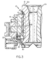
- the cooling air from the mold holder 14 can exit from the exterior of the mold elements 12a, 12b through openings 28, 30 at the top and bottom, respectively, of the mold holder 14, in the orientation illustrated in Fig. 3.
- the ends of mold holder sections 16, 18 are disengageably secured to diametrically opposed pairs of vertically extending connectors 32, 34 by cap screws 36.
- the connectors 32, 34 have radially inwardly projecting tabs 32a, 32b and 34a, 34b respectively, that are received in slots of the mold elements 12a, 12b to accurately circumferentially position the mold holder sections 16, 18 with respect to the mold elements 12a, 12b.
- the tabs 32a, 32b, and 34a, 34b also engage the free ends of the screens 26 to accurately circumferentially position the screens 26 with respect to the mold holder sections 16, 18, respectively.
- the fins 12e of the mold elements 12a, 12b have radially outwardly projecting portions 12e 1 , 12e 11 at the top and bottom, respectively, of each of the fins 12e.
- the portions 12e 1 , 12e 11 have shoulders that engage the top and bottom of the mold holder sections 16, 18, respectively, to accurately axially position the mold holder sections 16, 18 with respect to the mold elements 12a, 12b, respectively.
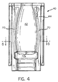
- Figs. 4-9 illustrate an assembly 40 that is made up of a mold section 42 contained within a section 46 of a mold holder 44. It is to be understood that the assembly 40 is annular in configuration during a molding operation with the mold section 42 joined end to end with a like mold section, not shown. Likewise, the mold holder 44 is annular in configuration during a molding operation, with the mold holder section 46 being joined end to end with a like mold holder section, also not shown. In any case, the mold assembly 40 is shown as being of a type suitable for use in an I.S. machine in performing the final, or blow, molding step on a molten glass parison of the type that has previously been formed in a parison molding assembly 10, as heretofore shown and described.
- the inside diameter of the mold section 42 often referred to as the cavity, will be substantially larger than that of the annular mold 12 of the mold assembly 10, and the wall thickness of a glass article in engagement with the mold section 42 will be substantially less than that in engagement with the annular mold 12.
- the mold section 42 is provided with a circumferentially disposed and axially extending spaced apart series of fins 42e that project outwardly from the mold section 42 to extend the outer surface of the mold section 42, and thereby increase the rate at which heat can be transferred from the glass article being blow molded in the mold assembly 40.
- the heat from the glass article that has transferred to the fins 42e is positively transferred away from the fins 42e by forced air cooling, and in that regard the mold holder section 46 is provided with a generally semi-cylindrical flow passage 50 extending axially therethrough.
- the flow passage 50 receives cooling air through an inlet 52, and is radially open on its interior to permit cooling air to flow radially outwardly from the flow passage 50 against the fins 42e of the mold section 42.
- a perforated screen 56 which is generally semi-cylindrically shaped, is affixed to the interior of the mold holder section 46.
- the perforations in the perforated screen 56 are sized and spaced to vary the cooling air flow of distribution vertically, and circumferentially if desired, to equalize the rate of cooling of an article being molded in the mold assembly 40, notwithstanding variations in cooling load due to localized variations in the diameter or wall thickness of the glass article.
- the mold holder section 46 has less axial extent than the mold section 42.
- the mold section 42 is vertically centered with respect to the mold holder section 46 by providing the mold section 42 with an outwardly facing groove 42d that receives an inwardly projecting tongue 46a of the mold holder section 46, and further by providing the mold section 42 with a downwardly projecting flange 42f that seats against an uppermost surface 46b of the mold holder section 46.
- the mold section 42 is disengageably secured to the mold holder section 46 by a vertical series of spaced apart cap screws 66 (Fig. 8) that extend through the mold holder section 46 to be threadably received in the mold section 42.
- vacuum assist is provided to help draw the molten glass article against the inside surface of the mold section 42.
- a diametrically opposed pair of vertical vacuum slots 70 is provided in the mold section 42, and each of the vacuum slots 70 is connected to a source of vacuum, not shown, by means of a vacuum tap 68.
- the vacuum in the vacuum passage 70 is being imposed on the bottom of an article being molded in the mold section 42 by a circumferentially spaced apart series of generally radially extending vacuum passage extensions 70a.
- the vacuum slots 70 are provided with openings 72 at the bottom thereof to ensure that the air contained within each vacuum slot 70 does not become stagnant.
Landscapes
- Engineering & Computer Science (AREA)
- Chemical & Material Sciences (AREA)
- Manufacturing & Machinery (AREA)
- Materials Engineering (AREA)
- Organic Chemistry (AREA)
- Moulds For Moulding Plastics Or The Like (AREA)
- Glass Compositions (AREA)
- Containers Having Bodies Formed In One Piece (AREA)
- Table Devices Or Equipment (AREA)
- Surface Treatment Of Glass (AREA)
- Re-Forming, After-Treatment, Cutting And Transporting Of Glass Products (AREA)
- Manufacture, Treatment Of Glass Fibers (AREA)
Abstract
Description
Claims (7)
- A mold arrangement of a glassware forming machine, comprising:in that each mold holder section (16, 18; 46) is generally semi-cylindrical in shape and designed for being inserted into, and coupled to a member of the glass forming machine which has plenum means (22) to be connected to the axially extending flow passage (20, 50) of the adjacent mold holder section, in thatan annular mold (12) formed by a pair of separable mold elements (12a, 12b, 42) which, during a molding step, are positioned end to end to enclose a single cavity, each mold element (12a, 12b,42) having a plurality of fins (12e; 42e) on its external surface, the tips thereof defining a curved surface;a mold holder (14; 44) formed by a pair of separable mold holder sections (16, 18; 46),each mold holder section (16, 18; 46) being connected to a respective mold element (12a, 12b; 42) surrounding at least a substantial axial lenth portion of each mold element;the mold holder sections (16, 18; 46) being positioned substantially end to end during the molding steps, and - together with the respective mold element to which each mold holder section is connected - positioned separated from one another during the steps of removing the molded glass article;each of the mold holder sections (16, 18; 46) having a fluid flow passage (20; 50) which extends through the holder section and has an outlet opening to permit fluid to flow against the fins (12e; 42e) of the adjacend mold element (12a, 12b; 42) to assist in cooling the hollow glass article in the mold;a perforated screen (26, 56) which is generally semi-cylindrically shaped corresponding to the envelop surface of the tips of the fins, being provided in the outlet opening of the respective flow passage (20; 50), which screen is configured to control the rate and pattern of fluid flowing from the flow passages (20, 50) against the fins ((12e, 42a) of the respective adjacent mold element (12a, 12b; 42), characterized in that the annular mold (12) and the mold holder (14; 44) which is generally annular in shape, too, form a mold assembly (10; 40) which includes said fluid flow passages (20; 50) and said screens (26; 56) for distributing cooling air over the mold (12),
the fins (12e; 42e) of each mold element (12a, 12b; 42) are circumferentially disposed and extend axially at least above the mold holder sections (16, 18; 46) to form exit openings (28; 42f) for the cooling air; and in that the screen (26;56) in the outlet opening of each flow passage (20; 50) thus is configured to control the rate and pattern of fluid flowing from the axially extending flow passage (20, 50) against the axially extending fins (12e,42e) of the respective adjacent mold element (12a), 12b; 42). - The apparatus according to claim 1
wherein the screen (26; 56) is affixed to the outlet opening of each mold holder section (16, 18; 46) and the perforations in each screen (26, 56) are sized and spaced in respect to the cooling fluid flow distribution as desired for the actual article to be molded. - The apparatus according to claim 1 or 2
wherein said connection between mold holder section (16, 18) and mold element (12a, 12b) is made by first and second pairs of connectors (32, 34), each connector being secured to a respective free end of one of said mold holder sections (16,18), so that the connectors (32, 34) of said pairs are opposite to another, each of said mold elements (12a, 12b) having a pair of inwardly projecting recesses, each of said connectors (32, 34) having an inwardly projecting tab (32a, 32b, 34a, 34b), which is received in a respective recess of the mold elements (12a, 12b) to accurately circumferentially position each pair of connectors (32, 34) and the mold holder section (16, 18) that is secured to it with respect to an adjacent one of said mold elements (12a, 12b). - The apparatus according to claim 3
wherein at least oner of the fins (12e) carried by each of said pair of mold elements (12a) 12b) has spaced apart upper and lower radially enlarged portions (12e', 12e"), said radially enlarged portions (12e', 12e") trapping an adjacent one of said mold holder sections (16, 18) to accurately axially position said each of said pair of mold elements (12a, 12b) with respect to said adjacent one of said mold holder sections, and to form an upper (28) and a lower (30) exit opening for the cooling air. - The apparatus according to any of claims 1 to 4
wherein the fluid flow passage (20; 50) in each mold holder section (16, 18, 46) is substantially semi-cylindrical in shape. - The apparatus according to claim 1 or 2
wherein said connection between mold holder section (46) and mold element (42) is made by threaded fastener means (66) extending through each of said mold holder sections (46), said fastener means (66) being threadably received in an adjacent on of said mold elements (42) for releasably securing said adjacent one of said mold elements (42) to the mold holder section (46) through which said fastener means extends. - The apparatus according to claim 6
wherein one of said mold holder sections (46) and said mold elements (42) has a groove (42d) that faces toward an adjacent one of the other of said mold holder sections and said mold sections, and wherein the other of said mold holder sections and said mold sections has a tongue (46a) being received in said groove (42d) to accurately axially position said one of said mold holder sections and said adjacent one of said mold sections with respect to one another.
Applications Claiming Priority (2)
| Application Number | Priority Date | Filing Date | Title |
|---|---|---|---|
| US08/679,781 US7698907B1 (en) | 1996-07-15 | 1996-07-15 | Mold assembly for glass articles |
| US679781 | 1996-07-15 |
Publications (3)
| Publication Number | Publication Date |
|---|---|
| EP0819654A2 EP0819654A2 (en) | 1998-01-21 |
| EP0819654A3 EP0819654A3 (en) | 1998-03-11 |
| EP0819654B1 true EP0819654B1 (en) | 2003-04-09 |
Family
ID=24728339
Family Applications (1)
| Application Number | Title | Priority Date | Filing Date |
|---|---|---|---|
| EP97111943A Expired - Lifetime EP0819654B1 (en) | 1996-07-15 | 1997-07-14 | Mold assembly for glass articles |
Country Status (19)
| Country | Link |
|---|---|
| US (1) | US7698907B1 (en) |
| EP (1) | EP0819654B1 (en) |
| JP (1) | JP3051702B2 (en) |
| CN (1) | CN1178870C (en) |
| AT (1) | ATE236858T1 (en) |
| AU (1) | AU728491B2 (en) |
| BR (1) | BR9703973A (en) |
| CA (1) | CA2210436C (en) |
| CO (1) | CO4700502A1 (en) |
| CZ (1) | CZ293715B6 (en) |
| DE (1) | DE69720608T2 (en) |
| DK (1) | DK0819654T3 (en) |
| EE (1) | EE03820B1 (en) |
| ES (1) | ES2196216T3 (en) |
| HU (1) | HU219390B (en) |
| PE (1) | PE30699A1 (en) |
| PL (1) | PL183887B1 (en) |
| PT (1) | PT819654E (en) |
| ZA (1) | ZA976221B (en) |
Families Citing this family (17)
| Publication number | Priority date | Publication date | Assignee | Title |
|---|---|---|---|---|
| US5900035A (en) * | 1997-08-11 | 1999-05-04 | Owens-Brockway Glass Container Inc. | Glass forming machine blank mold cooling apparatus |
| US6038889A (en) * | 1999-04-14 | 2000-03-21 | Libbey Glass Inc. | Cooling system for a glassware machine |
| US6758066B2 (en) | 2001-06-12 | 2004-07-06 | Owens-Brockway Glass Container Inc. | Glassware forming mold and method of manufacture |
| ES2208028B1 (en) * | 2001-11-12 | 2005-06-01 | Gamesa Desarrollos Aeronauticos, S.A. | SHELL MOLD FOR THE MANUFACTURE OF AIRLINER SHOES AND MOLD AS CONSTITUTED. |
| JP4274830B2 (en) * | 2003-03-25 | 2009-06-10 | アルプス電気株式会社 | Method for manufacturing optical element with holder |
| US7296442B2 (en) * | 2004-07-15 | 2007-11-20 | Owens-Brockway Glass Container Inc. | Neck ring cooling |
| US20060150681A1 (en) * | 2005-01-13 | 2006-07-13 | Owens-Brockway Glass Container Inc. | Glassware molds with cooling arrangement |
| CN101298355B (en) * | 2008-06-04 | 2010-10-06 | 常熟市伟恒模具铸造有限公司 | Mould for making glass container |
| WO2012119159A1 (en) * | 2011-02-21 | 2012-09-07 | Bennett Stanley William | A mould assembly. |
| CN103011558A (en) * | 2012-12-03 | 2013-04-03 | 德清才府玻璃股份有限公司 | Die used for bottle molding and stamping assembly |
| CN103056693B (en) * | 2013-01-29 | 2015-04-15 | 苏州东方模具科技股份有限公司 | Work fixture for machining inner cavities and joint closing surfaces of glass molds |
| CN103056695B (en) * | 2013-01-29 | 2015-04-15 | 苏州东方模具科技股份有限公司 | Fixture structure for machining inner cavities and joint closing surfaces of glass molds |
| CN103817544B (en) * | 2014-03-14 | 2016-08-17 | 无锡瑞真精机股份有限公司 | A kind of one-tenth blank mould die back facade fixture |
| CN104140191A (en) * | 2014-07-21 | 2014-11-12 | 德清才府玻璃股份有限公司 | Method for increasing air guiding quantity and durability of vertical cooling plate |
| US9546908B1 (en) | 2014-12-17 | 2017-01-17 | Owens-Brockway Glass Container Inc. | Glassware mold pyrometry |
| DE102015007695B4 (en) * | 2015-06-17 | 2020-06-10 | Heye lnternational GmbH | Arrangement for representing the vacuum operation in the molding process of a glass molding machine |
| FR3053037A1 (en) * | 2016-06-28 | 2017-12-29 | Etablissements Chpolansky | SYSTEM FOR MANUFACTURING GLASS OBJECTS |
Family Cites Families (35)
| Publication number | Priority date | Publication date | Assignee | Title |
|---|---|---|---|---|
| DE148875C (en) * | ||||
| US1633028A (en) * | 1922-06-12 | 1927-06-21 | Owens Bottle Co | Means for cooling molds |
| US2485836A (en) * | 1947-09-10 | 1949-10-25 | Hartford Empire Co | Glassware mold cooling means |
| US2928214A (en) * | 1955-12-15 | 1960-03-15 | Owens Illinois Glass Co | Cooling system for glass forming molds |
| US3024571A (en) * | 1957-07-25 | 1962-03-13 | Owens Illinois Glass Co | Apparatus for molding glass |
| US3137560A (en) * | 1960-01-07 | 1964-06-16 | Owens Illinois Glass Co | Apparatus for conditioning glass parison molds |
| US3251673A (en) * | 1960-09-08 | 1966-05-17 | Owens Illinois Glass Co | Apparatus for forming glass articles |
| US3268322A (en) * | 1961-04-13 | 1966-08-23 | Owens Illinois Inc | Glass forming apparatus |
| DE1284060B (en) * | 1961-05-27 | 1968-11-28 | Stinnes Hanns | Method for introducing and applying a heat conducting agent in hollow glass molds |
| US3133807A (en) * | 1961-06-09 | 1964-05-19 | Owens Illinois Glass Co | Mold cooling apparatus |
| US3338699A (en) * | 1964-04-22 | 1967-08-29 | Owens Illinois Inc | Glass forming apparatus |
| NL6703941A (en) | 1967-03-16 | 1968-09-17 | ||
| US3573025A (en) * | 1968-07-29 | 1971-03-30 | Lynch Corp | Pneumatically operated press plunger |
| US3607207A (en) * | 1969-02-18 | 1971-09-21 | Emhart Corp | Triple gob mold holder arm construction |
| US3586491A (en) * | 1969-04-23 | 1971-06-22 | Owens Illinois Inc | Mold cooling apparatus for glass forming machine |
| US3653870A (en) * | 1970-03-09 | 1972-04-04 | Emhart Corp | Holding and cooling device for glassware molds |
| US3617232A (en) | 1970-08-31 | 1971-11-02 | Anchor Hocking Corp | Self-acting connector for applying coolant air to glass molds |
| US3887350A (en) | 1974-02-11 | 1975-06-03 | Owens Illinois Inc | Fluid cooling of glass molds |
| US3888647A (en) * | 1974-04-15 | 1975-06-10 | Maul Bros Inc | Air cooled annular parison blank mold |
| GB1537837A (en) * | 1975-05-28 | 1979-01-04 | Emhart Ind | Glassware forming machines |
| US4009018A (en) * | 1975-07-07 | 1977-02-22 | Emhart Industries, Inc. | Glassware forming machine of the I. S. type with in-line mold motion |
| DE2609651C2 (en) * | 1976-03-09 | 1978-04-13 | Fa. Hermann Heye, 4962 Obernkirchen | Molding tool for molten gas |
| DE3040310C1 (en) * | 1980-10-25 | 1982-03-25 | Heye Hermann Fa | Pressure fluid distribution device for a mold for processing glass and similar thermoplastic materials |
| AU547417B2 (en) * | 1981-02-27 | 1985-10-17 | Emhart Industries Inc. | Mould opening and closing mechanism |
| US4512792A (en) | 1983-07-11 | 1985-04-23 | Owens-Illinois, Inc. | Cooling wind shut-off valve for glass forming mold |
| GB2152493B (en) | 1984-01-12 | 1987-02-04 | Emhart Ind | Mould arrangement for use in cyclicly operated glassware forming machine |
| GB2170796B (en) | 1985-02-13 | 1988-03-16 | Emhart Ind | Mould arrangement for a glassware forming machine |
| US4690703A (en) | 1986-04-18 | 1987-09-01 | Emhart Industries, Inc. | Mold cooling arrangement for use in a glassware forming machine |
| US4668269A (en) | 1986-06-19 | 1987-05-26 | Vidriera Monterrey, S.A. | System and method for the internal cooling of hot molds |
| US4750929A (en) | 1987-02-03 | 1988-06-14 | Liberty Glass Company | Cooling system for a glassware forming machine |
| US4842637A (en) | 1987-06-26 | 1989-06-27 | Glass Technology Development Corp. | Glassware forming machine with cooling system |
| EP0612697B1 (en) | 1993-02-24 | 1998-01-21 | Sulzer Chemtech AG | Purification of salt containing waste water by wet oxidation at supercritical conditions |
| ES2145071T3 (en) * | 1993-02-25 | 2000-07-01 | Owens Brockway Glass Container | APPARATUS FOR COOLING THE MOLD OF A GLASS ARTICLE FORMING MACHINE. |
| US5364437A (en) | 1993-03-10 | 1994-11-15 | I.M.T.E.C. Enterprises, Inc. | Glassware forming machine with spring-biased plenum |
| JP5515419B2 (en) | 2009-05-26 | 2014-06-11 | 日立化成デュポンマイクロシステムズ株式会社 | Positive photosensitive resin composition, method for producing a cured pattern film using the resin composition, electronic component and method for producing the same |
-
1996
- 1996-07-15 US US08/679,781 patent/US7698907B1/en not_active Expired - Fee Related
-
1997
- 1997-07-14 ZA ZA9706221A patent/ZA976221B/en unknown
- 1997-07-14 EP EP97111943A patent/EP0819654B1/en not_active Expired - Lifetime
- 1997-07-14 AT AT97111943T patent/ATE236858T1/en active
- 1997-07-14 PT PT97111943T patent/PT819654E/en unknown
- 1997-07-14 HU HU9701197A patent/HU219390B/en unknown
- 1997-07-14 ES ES97111943T patent/ES2196216T3/en not_active Expired - Lifetime
- 1997-07-14 AU AU28644/97A patent/AU728491B2/en not_active Expired
- 1997-07-14 CA CA002210436A patent/CA2210436C/en not_active Expired - Lifetime
- 1997-07-14 DK DK97111943T patent/DK0819654T3/en active
- 1997-07-14 CZ CZ19972226A patent/CZ293715B6/en not_active IP Right Cessation
- 1997-07-14 CN CNB971171319A patent/CN1178870C/en not_active Expired - Lifetime
- 1997-07-14 DE DE69720608T patent/DE69720608T2/en not_active Expired - Lifetime
- 1997-07-15 PL PL97321127A patent/PL183887B1/en unknown
- 1997-07-15 PE PE1997000628A patent/PE30699A1/en not_active IP Right Cessation
- 1997-07-15 CO CO97039931A patent/CO4700502A1/en unknown
- 1997-07-15 BR BR9703973A patent/BR9703973A/en not_active IP Right Cessation
- 1997-07-15 JP JP9222908A patent/JP3051702B2/en not_active Expired - Fee Related
- 1997-07-15 EE EE9700155A patent/EE03820B1/en unknown
Also Published As
| Publication number | Publication date |
|---|---|
| PL183887B1 (en) | 2002-07-31 |
| BR9703973A (en) | 1998-12-22 |
| ATE236858T1 (en) | 2003-04-15 |
| PT819654E (en) | 2003-08-29 |
| EE9700155A (en) | 1998-02-16 |
| US7698907B1 (en) | 2010-04-20 |
| AU2864497A (en) | 1998-01-22 |
| HU219390B (en) | 2001-03-28 |
| ES2196216T3 (en) | 2003-12-16 |
| HUP9701197A2 (en) | 1998-04-28 |
| CZ293715B6 (en) | 2004-07-14 |
| JPH10182170A (en) | 1998-07-07 |
| PL321127A1 (en) | 1998-01-19 |
| CA2210436C (en) | 2003-04-15 |
| DE69720608T2 (en) | 2004-02-12 |
| DK0819654T3 (en) | 2003-08-04 |
| ZA976221B (en) | 1998-02-03 |
| JP3051702B2 (en) | 2000-06-12 |
| EP0819654A3 (en) | 1998-03-11 |
| MX9705347A (en) | 1998-07-31 |
| DE69720608D1 (en) | 2003-05-15 |
| PE30699A1 (en) | 1999-03-23 |
| CN1178870C (en) | 2004-12-08 |
| EP0819654A2 (en) | 1998-01-21 |
| HU9701197D0 (en) | 1997-08-28 |
| AU728491B2 (en) | 2001-01-11 |
| CZ222697A3 (en) | 1998-03-18 |
| EE03820B1 (en) | 2002-08-15 |
| HUP9701197A3 (en) | 1999-04-28 |
| CO4700502A1 (en) | 1998-12-29 |
| CA2210436A1 (en) | 1998-01-15 |
| CN1174819A (en) | 1998-03-04 |
Similar Documents
| Publication | Publication Date | Title |
|---|---|---|
| CA2210436C (en) | Mold assembly for glass articles | |
| US4941815A (en) | Injection-blow molding apparatus | |
| US4592719A (en) | Apparatus for manufacturing plastic bottles from molded hollow preforms | |
| CA2159169C (en) | Modified plastic bottle injection blow-molding apparatus and process | |
| EP0110695B1 (en) | Blowhead arrangement for a glassware container manufacturing machine | |
| EP0242197B1 (en) | Mold cooling arrangement for use in a glassware forming machine | |
| US4983203A (en) | Cooling device for glass container forming machine | |
| US5358542A (en) | Glass container forming machine including neck ring mold cooling | |
| EP0612699B1 (en) | Mold cooling apparatus for a glassware forming machine | |
| EP1473281B1 (en) | Mold cooling system for a glass container forming machine | |
| US5571474A (en) | Blow moulding machine | |
| EP0896957B1 (en) | Glass forming machine blank mold cooling method and apparatus | |
| EP0099206A1 (en) | Method of cooling a mould | |
| MXPA97005347A (en) | Mounting of mold for articles of vid | |
| EP0895509B1 (en) | Mould cooling device in the glass making industry, relevant mould machining process and fitness process of said cooling device in different moulds for changing the production from a glass container to another | |
| JP4372949B2 (en) | Vacuum mechanism of I.S. machine | |
| KR960041094A (en) | Apparatus and method for forming glass article from molten glass | |
| EP0118288B1 (en) | Manufacture of moulded articles of glassware | |
| US20060150681A1 (en) | Glassware molds with cooling arrangement | |
| EP0089047A1 (en) | Transport neck ring | |
| EP0160297A2 (en) | Apparatus and method for economically producing blowmolded containers having open necks on opposing faces thereof | |
| ITPN940064A1 (en) | MOLD COOLING DEVICE IN THE GLASS INDUSTRY, MOLD PROCESSING PROCESS IN THE GLASS INDUSTRY TO ADAPT THEM TO A NEW PRODUCTION TECHNOLOGY AND PROCESS OF ADAPTATION OF THIS PRODUCTION COOLING DEVICE | |
| MXPA98006429A (en) | Method and apparatus for cooling a machine-building stamp to manufacture vid objects | |
| MXPA98008491A (en) | Method and apparatus for introducing gutiformes glass masses in a vid container forming machine | |
| KR20000017179U (en) | Press forming apparatus for crt glass |
Legal Events
| Date | Code | Title | Description |
|---|---|---|---|
| PUAI | Public reference made under article 153(3) epc to a published international application that has entered the european phase |
Free format text: ORIGINAL CODE: 0009012 |
|
| AK | Designated contracting states |
Kind code of ref document: A2 Designated state(s): AT BE CH DE DK ES FI FR GB GR IT LI NL PT SE |
|
| PUAL | Search report despatched |
Free format text: ORIGINAL CODE: 0009013 |
|
| AK | Designated contracting states |
Kind code of ref document: A3 Designated state(s): AT BE CH DE DK ES FI FR GB GR IE IT LI LU MC NL PT SE |
|
| 17P | Request for examination filed |
Effective date: 19980907 |
|
| AKX | Designation fees paid | ||
| RBV | Designated contracting states (corrected) | ||
| RBV | Designated contracting states (corrected) |
Designated state(s): AT BE CH DE DK ES FI FR GB GR IT LI NL PT SE |
|
| 17Q | First examination report despatched |
Effective date: 20000316 |
|
| GRAG | Despatch of communication of intention to grant |
Free format text: ORIGINAL CODE: EPIDOS AGRA |
|
| GRAG | Despatch of communication of intention to grant |
Free format text: ORIGINAL CODE: EPIDOS AGRA |
|
| GRAG | Despatch of communication of intention to grant |
Free format text: ORIGINAL CODE: EPIDOS AGRA |
|
| GRAH | Despatch of communication of intention to grant a patent |
Free format text: ORIGINAL CODE: EPIDOS IGRA |
|
| GRAH | Despatch of communication of intention to grant a patent |
Free format text: ORIGINAL CODE: EPIDOS IGRA |
|
| GRAA | (expected) grant |
Free format text: ORIGINAL CODE: 0009210 |
|
| AK | Designated contracting states |
Designated state(s): AT BE CH DE DK ES FI FR GB GR IT LI NL PT SE |
|
| REG | Reference to a national code |
Ref country code: GB Ref legal event code: FG4D |
|
| REG | Reference to a national code |
Ref country code: SE Ref legal event code: TRGR Ref country code: CH Ref legal event code: EP |
|
| REG | Reference to a national code |
Ref country code: CH Ref legal event code: NV Representative=s name: BOVARD AG PATENTANWAELTE |
|
| REG | Reference to a national code |
Ref country code: DK Ref legal event code: T3 |
|
| REG | Reference to a national code |
Ref country code: GR Ref legal event code: EP Ref document number: 20030402516 Country of ref document: GR |
|
| REG | Reference to a national code |
Ref country code: ES Ref legal event code: FG2A Ref document number: 2196216 Country of ref document: ES Kind code of ref document: T3 |
|
| ET | Fr: translation filed | ||
| PLBE | No opposition filed within time limit |
Free format text: ORIGINAL CODE: 0009261 |
|
| STAA | Information on the status of an ep patent application or granted ep patent |
Free format text: STATUS: NO OPPOSITION FILED WITHIN TIME LIMIT |
|
| 26N | No opposition filed |
Effective date: 20040112 |
|
| REG | Reference to a national code |
Ref country code: CH Ref legal event code: PFA Owner name: OWENS-BROCKWAY GLASS CONTAINER INC. Free format text: OWENS-BROCKWAY GLASS CONTAINER INC.#ONE SEA GATE#TOLEDO, OHIO 43666 (US) -TRANSFER TO- OWENS-BROCKWAY GLASS CONTAINER INC.#ONE SEA GATE#TOLEDO, OHIO 43666 (US) |
|
| PGFP | Annual fee paid to national office [announced via postgrant information from national office to epo] |
Ref country code: FI Payment date: 20130729 Year of fee payment: 17 |
|
| PG25 | Lapsed in a contracting state [announced via postgrant information from national office to epo] |
Ref country code: FI Free format text: LAPSE BECAUSE OF NON-PAYMENT OF DUE FEES Effective date: 20140714 |
|
| PGFP | Annual fee paid to national office [announced via postgrant information from national office to epo] |
Ref country code: CH Payment date: 20150914 Year of fee payment: 19 Ref country code: DK Payment date: 20150727 Year of fee payment: 19 |
|
| PGFP | Annual fee paid to national office [announced via postgrant information from national office to epo] |
Ref country code: AT Payment date: 20150619 Year of fee payment: 19 Ref country code: BE Payment date: 20150727 Year of fee payment: 19 Ref country code: SE Payment date: 20150729 Year of fee payment: 19 |
|
| REG | Reference to a national code |
Ref country code: FR Ref legal event code: PLFP Year of fee payment: 20 |
|
| PGFP | Annual fee paid to national office [announced via postgrant information from national office to epo] |
Ref country code: PT Payment date: 20160623 Year of fee payment: 20 |
|
| PGFP | Annual fee paid to national office [announced via postgrant information from national office to epo] |
Ref country code: NL Payment date: 20160726 Year of fee payment: 20 |
|
| PGFP | Annual fee paid to national office [announced via postgrant information from national office to epo] |
Ref country code: IT Payment date: 20160722 Year of fee payment: 20 Ref country code: GB Payment date: 20160727 Year of fee payment: 20 Ref country code: DE Payment date: 20160726 Year of fee payment: 20 |
|
| PGFP | Annual fee paid to national office [announced via postgrant information from national office to epo] |
Ref country code: FR Payment date: 20160726 Year of fee payment: 20 Ref country code: GR Payment date: 20160727 Year of fee payment: 20 |
|
| PG25 | Lapsed in a contracting state [announced via postgrant information from national office to epo] |
Ref country code: BE Free format text: LAPSE BECAUSE OF NON-PAYMENT OF DUE FEES Effective date: 20160731 |
|
| PGFP | Annual fee paid to national office [announced via postgrant information from national office to epo] |
Ref country code: ES Payment date: 20160726 Year of fee payment: 20 |
|
| REG | Reference to a national code |
Ref country code: DK Ref legal event code: EBP Effective date: 20170131 |
|
| REG | Reference to a national code |
Ref country code: CH Ref legal event code: PL |
|
| REG | Reference to a national code |
Ref country code: SE Ref legal event code: EUG |
|
| REG | Reference to a national code |
Ref country code: AT Ref legal event code: MM01 Ref document number: 236858 Country of ref document: AT Kind code of ref document: T Effective date: 20160714 |
|
| PG25 | Lapsed in a contracting state [announced via postgrant information from national office to epo] |
Ref country code: CH Free format text: LAPSE BECAUSE OF NON-PAYMENT OF DUE FEES Effective date: 20160731 Ref country code: LI Free format text: LAPSE BECAUSE OF NON-PAYMENT OF DUE FEES Effective date: 20160731 Ref country code: SE Free format text: LAPSE BECAUSE OF NON-PAYMENT OF DUE FEES Effective date: 20160715 |
|
| PG25 | Lapsed in a contracting state [announced via postgrant information from national office to epo] |
Ref country code: AT Free format text: LAPSE BECAUSE OF NON-PAYMENT OF DUE FEES Effective date: 20160714 |
|
| REG | Reference to a national code |
Ref country code: DE Ref legal event code: R071 Ref document number: 69720608 Country of ref document: DE |
|
| REG | Reference to a national code |
Ref country code: NL Ref legal event code: MK Effective date: 20170713 |
|
| REG | Reference to a national code |
Ref country code: GB Ref legal event code: PE20 Expiry date: 20170713 |
|
| PG25 | Lapsed in a contracting state [announced via postgrant information from national office to epo] |
Ref country code: GB Free format text: LAPSE BECAUSE OF EXPIRATION OF PROTECTION Effective date: 20170713 Ref country code: PT Free format text: LAPSE BECAUSE OF EXPIRATION OF PROTECTION Effective date: 20170721 |
|
| PG25 | Lapsed in a contracting state [announced via postgrant information from national office to epo] |
Ref country code: DK Free format text: LAPSE BECAUSE OF NON-PAYMENT OF DUE FEES Effective date: 20160731 |
|
| REG | Reference to a national code |
Ref country code: ES Ref legal event code: FD2A Effective date: 20180508 |
|
| PG25 | Lapsed in a contracting state [announced via postgrant information from national office to epo] |
Ref country code: ES Free format text: LAPSE BECAUSE OF EXPIRATION OF PROTECTION Effective date: 20170715 |