EP0819601B1 - Hinsichtlich Fluidturbulenzen modifizierte Oberfläche - Google Patents
Hinsichtlich Fluidturbulenzen modifizierte Oberfläche Download PDFInfo
- Publication number
- EP0819601B1 EP0819601B1 EP97401426A EP97401426A EP0819601B1 EP 0819601 B1 EP0819601 B1 EP 0819601B1 EP 97401426 A EP97401426 A EP 97401426A EP 97401426 A EP97401426 A EP 97401426A EP 0819601 B1 EP0819601 B1 EP 0819601B1
- Authority
- EP
- European Patent Office
- Prior art keywords
- amplitude
- waves
- pipe
- turbulence
- fluid
- Prior art date
- Legal status (The legal status is an assumption and is not a legal conclusion. Google has not performed a legal analysis and makes no representation as to the accuracy of the status listed.)
- Expired - Lifetime
Links
- 239000012530 fluid Substances 0.000 title claims description 29
- VNWKTOKETHGBQD-UHFFFAOYSA-N methane Chemical compound C VNWKTOKETHGBQD-UHFFFAOYSA-N 0.000 claims description 24
- 239000003345 natural gas Substances 0.000 claims description 10
- 239000002131 composite material Substances 0.000 claims description 3
- 239000007789 gas Substances 0.000 description 22
- 238000000576 coating method Methods 0.000 description 11
- 239000011248 coating agent Substances 0.000 description 10
- 230000000694 effects Effects 0.000 description 10
- 238000004519 manufacturing process Methods 0.000 description 7
- 230000008901 benefit Effects 0.000 description 6
- 230000002401 inhibitory effect Effects 0.000 description 5
- 239000001257 hydrogen Substances 0.000 description 3
- 229910052739 hydrogen Inorganic materials 0.000 description 3
- 230000005764 inhibitory process Effects 0.000 description 3
- 239000000126 substance Substances 0.000 description 3
- VGGSQFUCUMXWEO-UHFFFAOYSA-N Ethene Chemical compound C=C VGGSQFUCUMXWEO-UHFFFAOYSA-N 0.000 description 2
- 239000005977 Ethylene Substances 0.000 description 2
- 230000015572 biosynthetic process Effects 0.000 description 2
- 238000003486 chemical etching Methods 0.000 description 2
- 230000007423 decrease Effects 0.000 description 2
- 230000014509 gene expression Effects 0.000 description 2
- 150000002431 hydrogen Chemical class 0.000 description 2
- 230000003993 interaction Effects 0.000 description 2
- 239000000463 material Substances 0.000 description 2
- 229920000642 polymer Polymers 0.000 description 2
- 238000003786 synthesis reaction Methods 0.000 description 2
- UGFAIRIUMAVXCW-UHFFFAOYSA-N Carbon monoxide Chemical compound [O+]#[C-] UGFAIRIUMAVXCW-UHFFFAOYSA-N 0.000 description 1
- 239000004593 Epoxy Substances 0.000 description 1
- JOYRKODLDBILNP-UHFFFAOYSA-N Ethyl urethane Chemical compound CCOC(N)=O JOYRKODLDBILNP-UHFFFAOYSA-N 0.000 description 1
- UFHFLCQGNIYNRP-UHFFFAOYSA-N Hydrogen Chemical compound [H][H] UFHFLCQGNIYNRP-UHFFFAOYSA-N 0.000 description 1
- 229910000831 Steel Inorganic materials 0.000 description 1
- 230000003321 amplification Effects 0.000 description 1
- 238000004873 anchoring Methods 0.000 description 1
- 229910002091 carbon monoxide Inorganic materials 0.000 description 1
- 230000003247 decreasing effect Effects 0.000 description 1
- 238000000151 deposition Methods 0.000 description 1
- 238000010586 diagram Methods 0.000 description 1
- 238000005530 etching Methods 0.000 description 1
- 230000001747 exhibiting effect Effects 0.000 description 1
- 238000002474 experimental method Methods 0.000 description 1
- 238000002955 isolation Methods 0.000 description 1
- 238000005304 joining Methods 0.000 description 1
- 229910052751 metal Inorganic materials 0.000 description 1
- 239000002184 metal Substances 0.000 description 1
- 238000000034 method Methods 0.000 description 1
- 239000000203 mixture Substances 0.000 description 1
- 238000000465 moulding Methods 0.000 description 1
- 238000003199 nucleic acid amplification method Methods 0.000 description 1
- 239000003973 paint Substances 0.000 description 1
- 230000000737 periodic effect Effects 0.000 description 1
- 239000010959 steel Substances 0.000 description 1
- 230000002195 synergetic effect Effects 0.000 description 1
Images
Classifications
-
- F—MECHANICAL ENGINEERING; LIGHTING; HEATING; WEAPONS; BLASTING
- F15—FLUID-PRESSURE ACTUATORS; HYDRAULICS OR PNEUMATICS IN GENERAL
- F15D—FLUID DYNAMICS, i.e. METHODS OR MEANS FOR INFLUENCING THE FLOW OF GASES OR LIQUIDS
- F15D1/00—Influencing flow of fluids
- F15D1/02—Influencing flow of fluids in pipes or conduits
- F15D1/06—Influencing flow of fluids in pipes or conduits by influencing the boundary layer
- F15D1/065—Whereby an element is dispersed in a pipe over the whole length or whereby several elements are regularly distributed in a pipe
-
- B—PERFORMING OPERATIONS; TRANSPORTING
- B64—AIRCRAFT; AVIATION; COSMONAUTICS
- B64C—AEROPLANES; HELICOPTERS
- B64C21/00—Influencing air flow over aircraft surfaces by affecting boundary layer flow
- B64C21/10—Influencing air flow over aircraft surfaces by affecting boundary layer flow using other surface properties, e.g. roughness
-
- Y—GENERAL TAGGING OF NEW TECHNOLOGICAL DEVELOPMENTS; GENERAL TAGGING OF CROSS-SECTIONAL TECHNOLOGIES SPANNING OVER SEVERAL SECTIONS OF THE IPC; TECHNICAL SUBJECTS COVERED BY FORMER USPC CROSS-REFERENCE ART COLLECTIONS [XRACs] AND DIGESTS
- Y02—TECHNOLOGIES OR APPLICATIONS FOR MITIGATION OR ADAPTATION AGAINST CLIMATE CHANGE
- Y02T—CLIMATE CHANGE MITIGATION TECHNOLOGIES RELATED TO TRANSPORTATION
- Y02T50/00—Aeronautics or air transport
- Y02T50/10—Drag reduction
Definitions
- the present invention relates to a structure having a surface adapted to reduce the turbulence problems existing inside the boundary layer of a moving fluid with respect to the surface.
- the invention finds in particular, but not exclusively, its application in the field of transporting pressurized gas through a pipe.
- friction occurs between the gas under pressure in flow and the wall of the internal pipe, which lead to losses significant load.
- Pressure losses must be compensated for ensure optimum transport of the fluid in the pipe.
- the gas transported is natural gas comprising at least 90% methane.
- the invention can also be used for the transport of fluids having the form of a turbulent flow. It also targets the transport of industrial gases, such as synthesis gases, hydrogen, ethylene, etc.
- These structures can be formed by surfaces provided with ridges present in the region of turbulence.
- the axis of the streaks extends in the direction of fluid flow. The role of these streaks is to reduce turbulence phenomena existing inside the boundary layer of the fluid in motion and, by reducing friction between the surface and the fluid, minimize pressure losses.
- Streaks or ways to reduce pressure drop, can take different geometries, and their number can be chosen according to transport conditions, and / or the nature of the fluid in order to obtain the minimum pressure drop.
- the prior art also cites the advantageous use of streaks having a cylindrical shape, which would make it possible to obtain anchoring effects of the fluid, thus avoiding the amplification of the turbulence phenomenon in the boundary layer flowing fluid.
- boundary layer denotes a zone of fluid in flow in a pipe for example near the wall or the internal surface of this pipe, in which the speed gradient is the higher.
- Another structural architecture that is envisioned in art anterior consists in associating longitudinal grooves (in the direction of fluid flow), with a device arranged and suspended relative to these grooves, the latter having the role of "breaking" the large vortices amplitude, while the longitudinal grooves will act on the vortices of low amplitude.
- Such an association is however complex and cumbersome.
- US Pat. No. 5,386,955 describes a specific arrangement similar grooves or ridges. This document teaches to have the grooves of several sizes, according to a chosen arrangement and sequence, to inhibit vortices of different scales inside the layer fluid limit.
- the present invention offers the advantage of benefiting simultaneously and at any point of a turbulence inhibiting effect on at least two scales different, in particular by superimposing geometric profiles corresponding to different scales.
- the present invention relates to a pipe for transporting a fluid, the internal wall of the pipe having grooves making it possible to inhibit the turbulence phenomena of a fluid flowing in the pipe, the grooves extending substantially longitudinally in the direction of movement. of said fluid.
- the grooves form at least a first system of waves of amplitude a 1 , and at least a second system of waves of amplitude a 2 , the second system of waves being arranged so as to be superimposed on the first system of waves, the first wave system allowing at least to inhibit turbulence of high amplitude and the second wave system making it possible to inhibit at least turbulence of low amplitude.
- the geometric profile delimiting the first wave system forms preferably the baseline of the geometric profile delimiting the second wave system.
- the amplitude a 1 is greater than the amplitude a 2 , the amplitude a 1 being taken with respect to the base surface of the first wave system and the amplitude a 2 with respect to the base surface of the second system wave.
- the first wave system has a substantially shaped profile polygonal comprising n sides and r vertices.
- the value of this angle ⁇ is positive, i.e. the value of the angle ⁇ counted inside the polygon is less than 180 °.
- the sum of all the angles entered for all or the majority of the length of the polygonal shape is substantially equal to ⁇ (n-2).
- the number of sides is greater than 25, or the number r of vertices satisfies the following condition: 1 6 2 ⁇ r 2 ⁇ 0.01
- the present invention advantageously finds its application for form the internal wall of a pipe for example having a geometry circular used for the transport of natural gas under pressure, in conditions for example mentioned above at the beginning of the description.
- the inner wall having the specific features of the present invention extends over at least part of the length and the circumference of the transport. It can be arranged in sections inside the pipe, the sections being separated by predefined intervals, for example.
- the transport line may have an internal coating having the characteristics of the aforementioned structure, including the grooves form the first and second wave systems which are realized, by example mechanically and / or chemically so as to obtain the geometric characteristics necessary to inhibit turbulence.
- the gas transport pipe comprising at least one structure having the aforementioned characteristics, is preferably carried out in composite material.
- the present invention can be applied to the transport of a gas, for example a gas in turbulent flow, from a production well to a place of treatment, for example.
- the gas can be expanded at the outlet of the well to a pressure value at least equal to 5 MPa, Then, it is possible to send the gas in a pipe having a section of value chosen so that the speed of passage of the transported gas is, for example, greater than 10 m / s, the pipe comprising, for example over at least part of its length, a structure having the above characteristics, in order to inhibit turbulence in the boundary layer adjacent to the structure.
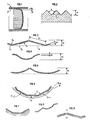
- Figure 1 shows the general shape of the velocity profile of a fluid in flow in a pipe 1, the flow of the fluid being a flow says "turbulent".
- the shear for turbulent flows is very important in a layer of thickness "e" relatively reduced and close to the internal wall 2 of the pipe 1, the speed field at the center of the fluid in flow being substantially uniform, unlike the velocity field observed in the thickness boundary layer "e".
- the idea of the invention is to reduce the effects viscous dissipation related to turbulence, in the immediate vicinity of the wall, using a structure with specific characteristics described below.
- Figure 2 shows schematically along a cross section perpendicular to their general direction, an example of geometry of grooves or grooves of simple form described in the prior art.
- the striated structures or coatings described in this figure form a longitudinal wave system, which extend in the direction of fluid flow, and which reduce the dissipation effects viscous linked to the presence of small-scale vortex movements.
- a wave 3 represented in FIG. 2 is characterized by a succession of concave parts and convex parts, delimited by a broken line.
- the line segments joining the vertices of this line broken form at each vertex an angle ⁇ , ⁇ which is such that the sum algebraic of the angles ⁇ formed by the two successive line segments delimiting a concave part, counted positively, and ⁇ angles formed by the two line segments delimiting a convex part, counted negatively, is zero or substantially equal to 0.
- Each line segment thus forms an alternating positive and negative angle with the preceding one.
- the amplitude "a" of waves 3 is in this case, for example, of the order of a few tenths of a millimeter.
- Such a wave geometry makes it possible to attenuate or inhibit a turbulence with a substantially constant amplitude scale inside of the boundary layer of the fluid. We can thus dampen turbulence at low scale present in the immediate vicinity of the internal wall. However, in the majority of cases, the flows are characterized by turbulence at several scales, and this wave system turns out to be insufficient or perfectible.
- the idea of the present invention therefore consists in having a structure which can act on turbulences with amplitude levels different. It has been discovered that to cushion the effects of turbulence at different scales for example, in an industrial transport line of natural gas, better results are obtained by overlapping at least two geometries that will dampen the turbulence effects having at at least two amplitude levels (at least two different scales).
- Figures 3 to 5 schematize according to a cross section different forms of structure that can take the wall of a pipe La wall surface can thus include at least two series of means, superimposed on each other, each of which has the function of inhibiting minus different vortices or turbulences of scale occurring in a thickness of a flowing gas with respect to the wall and to the near the surface or internal wall of the structure.
- a wave system a set formed by a series of inhibiting means turbulence which can be in the form of waves.
- the first wave system forms the basis of the second wave system.
- the first wave system 0 1 of amplitude a 1 has the main function of inhibiting at least the vortex movements of high amplitude, while the second wave system 0 2 of amplitude a 2 has the function of at least inhibit vortex movements of small amplitude, in the vicinity of the wall, the expressions vortex movements and turbulence designating identical phenomena.
- the ratio between the amplitudes of the two wave systems a 1 / a 2 is, for example, of the order of 10.
- the value of the amplitude a 1 is for example of the order of a millimeter, approximately 1 mm, while the value of a 2 is chosen to be substantially equal to 1/10 th of a mm.
- the profile of the first wave system 0 1 described in FIG. 3 is, for example, in the form of a broken line comprising a succession of substantially rectilinear parts A 1 , to inhibit turbulence of high amplitude. On these rectilinear parts A 1 is superimposed the second wave system 0 2 whose function is to inhibit turbulence of low amplitude.
- FIG. 4 describes a structure presenting a first system of waves 0 1 of sinusoidal shape forming at least partially the wall of a pipe, the sinusoid being substantially perpendicular to the direction of flow of the fluid.
- this wave system which inhibits vortex movements of high amplitude, is superimposed the second wave system 0 2 inhibiting turbulence of low amplitude.
- the amplitudes a 1 and a 2 can take values which are substantially identical to those described in relation to FIG. 3.
- the structure according to the invention comprises a first wave system 01 formed by a series of elements in projection whose angle at the top is relatively small.
- the profile of greatest amplitude, corresponding to the first wave system is inscribed between two surfaces S 1 , S 2 , the distance of which corresponds substantially to the amplitude a 1 .
- the value of the amplitude a 1 is preferably less than 0.005 times the value of the internal diameter D of the pipe.
- the value of the greatest amplitude of the wave a 1 is less than 4.6 mm.
- the structural geometry shown in Figure 5 shows as advantage of achieving a larger amplitude profile with a loss of smaller section. Indeed, the specific geometric shape of the first wave system as shown in this figure generates a loss of section open to the lower drain.
- the second O 2 wave system is formed by a broken line comprising several successive straight line segments. It is understood that without departing from the invention, other forms of geometry can be envisaged for the second system of waves.
- Figure 6 describes, along a cross section of a pipe circular, a structure which is particularly well suited to inhibit effects of turbulence with several different amplitudes.
- the structure as shown diagrammatically in FIG. 6 presents two wave systems making it possible to damp at least two different scales of turbulence. It is formed of a first wave system having a polygonal type profile (PI) which fits between two surfaces S 1 , S 2 distant by an amplitude a 1 for example. On this first PI wave system is superimposed a second wave system 0 2 of amplitude a 2 having, for example a geometry similar to that of the wave systems described in FIGS. 3 to 5. The amplitude a 2 is less than that of amplitude a 1 .
- PI polygonal type profile
- the PI polygonal profile is composed of several sides, or segments of right di.
- the line segments di are interconnected, two segments of straight line, for example (di-1, di), or (di, di + 1), forming an angle between them having preferably a positive value, thus defining a vertex r.
- the sum angles ⁇ expressed in radians is substantially equal to ⁇ (n-2).
- the wave system described in figure 2 presents on the contrary angles alternately positive and negative.
- a structure having such a polygonal profile makes it possible to damp the turbulence, the amplitude of which is substantially equal to a 1 which corresponds to the distance between the surface S 1 inscribed inside the polygon and the surface passing through the vertices r, the second system 0 2 will inhibit turbulence of amplitude substantially close to a 2 .
- the structure described in Figure 6 also offers the advantage of keeping a relatively small loss of open section at flow, and preferably less than 1% of the total circular section of the pipe.
- Such a structure advantageously makes it possible to inhibit a range of turbulences which can take different forms, in particular turbulences comprising several amplitudes.
- the value of a 1 can be chosen to be greater than that of the system shown in FIG. 3, while retaining a structure of simple shape, so as to inhibit turbulence of greater amplitudes.
- FIG. 6 shows a second wave system 0 2 of amplitude a 2 having a shape substantially similar to that of the wave system of FIG. 2.
- PI polygonal
- second wave system of different geometry for example formed by a periodic series of projecting elements of geometry for example analogous to the geometry of the wave profile 0 1 shown in FIG. 5.
- FIG. 7 describes a structure exhibiting this characteristic.
- Turbulence phenomena whatever their amplitude and their form being linked due to the viscosity of the fluid, it is possible to envisage overlays and combinations of wave systems that are going to have a synergistic effect to optimize the inhibition of turbulence.
- FIG. 8 describes an embodiment for a structure comprising a first polygonal type wave system on which is superimposed a second wave system having a combination of two geometries dondes.
- the waves of the second system can have amplitudes different. In any case the largest of the amplitudes of the second wave system is less than the amplitude of the first wave system.
- the structure according to the invention is for example used to form part of a transport pipe of a pressurized natural gas from a production well and sent to a place treatment for example.
- Natural gas is expanded at the outlet of the well to a value of pressure at least equal to 5 MPa then sent through a pipe comprising for example an internal wall at least in the part connected to the exit from the production well.
- the section of the production line is preferably chosen to obtain a gas passage speed or a average gas flow velocity, i.e. the flow ratio gas volume on the passage section, greater than 10 m / s
- a particularly important application of a structure comprising the characteristics of the invention relate, as indicated above, to transport of natural gas under pressure, comprising at least 90% of methane.
- the gas pressure value is preferably greater than 50 bars and the average flow velocity preferably respects the value cited above.
- Such flow conditions and the presence of this type of structure are preferably observed for transporting industrial gases under pressure, for example to convey a synthesis gas formed of a mixture carbon monoxide and hydrogen or to transport hydrogen, ethylene.
- the transport pipe which includes the structural characteristics according to the invention can be a metal pipe, for example steel.
- the wave systems are for example made by grooving mechanically the internal surface of the pipe.
- the internal coating can be achieved by placing on the surface internal of a transport pipe a film, for example a film of material polymer, one of the faces of which has a system of longitudinal waves, i.e. a wave system having a substantially parallel main axis to the flow direction.
- a film for example a film of material polymer, one of the faces of which has a system of longitudinal waves, i.e. a wave system having a substantially parallel main axis to the flow direction.
- These waves can be produced for example by mechanical groove, by chemical etching or by molding.
- the internal coating can also be produced by depositing a coating, and by mechanically generating the grooves or by etching chemical in the coating.
- the coating may for example be based on paint epoxy, urethane or epoxy-urethane.
- the internal coating can also be in the form of several superimposed or multi-layered layers, for example in the form of bi-layers or tri-layers. We can also superimpose one or more films polymer and coating based coating.
- FIG. 9 An exemplary embodiment of such a structure is shown in FIG. 9.
- a film (f) comprising a surface structure forming a system of waves of amplitude a 2 is deposited on a support surface (S) comprising a structure surface forming a wave system of amplitude a 1 .
- the pipe can also be a flexible pipe made in composite material whose internal surface has a wave system forming the subject of the present invention.
- the waves have a general longitudinal direction, parallel to the axis of gas flow and preferably they are continuous. However, they may deviate slightly from this direction, not be strictly straight, they can also be discontinuous and interrupted on a part of their length without departing from the scope of the invention.
- the layers can be made of material of different nature and techniques mechanical and chemical can be used to form the grooves of a same part of a pipe.
Landscapes
- Engineering & Computer Science (AREA)
- Physics & Mathematics (AREA)
- Fluid Mechanics (AREA)
- Mechanical Engineering (AREA)
- General Engineering & Computer Science (AREA)
- Aviation & Aerospace Engineering (AREA)
- Rigid Pipes And Flexible Pipes (AREA)
- Pipe Accessories (AREA)
- Electric Cable Installation (AREA)
Claims (7)
- Rohrleitung zum Befördern eines Fluids, wobei die Innenwand der Rohrleitung Rillen umfaßt, welche es ermöglichen, Turbolenzerscheinungen eines in der Rohrleitung strömenden Fluids zu verhindern, wobei die Rillen sich im wesentlichen longitudinal in der Bewegungsrichtung des besagten Fluids erstrecken, die Rillen bilden mindestens ein erstes Wellensystem (O1) mit der Amplitude a1 und mindestens ein zweites Wellensystem (O2) mit der Amplitude a2, wobei das besagte zweite Wellensystem (O2) dem besagten ersten Wellensystem (O1) überlagert ist, wobei das besagte erste Wellensystem (O1) es mindestens ermöglicht, die Turbulenzen mit großer Amplitude zu verhindern und wobei das besagte zweite Wellensystem (O2) es mindestens ermöglicht, die Turbulenzen mit kleiner Amplitude zu verhindern, wobei die Amplitude a1 des ersten Wellensystems (O1) größer ist als die Amplitude a2 des zweiten Wellensystems (O2), wobei die Amplitude a1 relativ zu der Grundfläche des ersten Wellensystems (O1) gemessen wird und die Amplitude a2 relativ zu der Grundfläche des zweiten Wellensystems (O2) genommen wird, dadurch gekennzeichnet, daß das erste Wellensystem ein Profil in Form eines Vielecks aufweist, umfassend n Seiten und r Spitzen, einen durch zwei aufeinander folgende Spitzen begrenzten geraden Abschnitt (di), welcher im Verhältnis zu dem vorhergehenden und/oder dem folgenden geraden Abschnitt (di-1, di+1) einen Winkel alpha im Innern des Vielecks bildet, wobei der Wert des besagten Winkels alpha unterhalb von 180° liegt.
- Rohrleitung nach Anspruch 1, in welcher die für die Gesamtheit der vieleckigen Form gebildete Summe aller Winkel alpha im wesentlichen gleich pi(n-2) ist.
- Rohrleitung nach einem der Ansprüche 1 und 2, in welcher die Anzahl n der Seiten oberhalb von 25 liegt.
- Rohrleitung nach einem der Ansprüche 1 bis 3, in welcher die Anzahl r der Spitzen die folgende Bedingung erfüllt: 1/6 * (2pi/r)2 < 0,01
- Rohrleitung nach einem der Ansprüche 1 bis 4, in welcher die Rillen mechanisch oder chemisch in einer internen Verkleidung ausgebildet sind.
- Rohrleitung nach einem der Ansprüche 1 bis 5, ausgeführt in Verbundwerkstoff.
- Rohrleitung nach einem der Ansprüche 1 bis 6, in welcher das Fluid ein natürliches Gas ist, welches unter einem Druck von mindestens gleich 5 MPa steht und mit mindestens 10 m/s strömt.
Applications Claiming Priority (2)
| Application Number | Priority Date | Filing Date | Title |
|---|---|---|---|
| FR9608914 | 1996-07-15 | ||
| FR9608914A FR2751049B1 (fr) | 1996-07-15 | 1996-07-15 | Surface modifiee pour reduire les turbulences d'un fluide et procede de transport |
Publications (2)
| Publication Number | Publication Date |
|---|---|
| EP0819601A1 EP0819601A1 (de) | 1998-01-21 |
| EP0819601B1 true EP0819601B1 (de) | 2004-09-08 |
Family
ID=9494125
Family Applications (1)
| Application Number | Title | Priority Date | Filing Date |
|---|---|---|---|
| EP97401426A Expired - Lifetime EP0819601B1 (de) | 1996-07-15 | 1997-06-20 | Hinsichtlich Fluidturbulenzen modifizierte Oberfläche |
Country Status (6)
| Country | Link |
|---|---|
| US (1) | US6193191B1 (de) |
| EP (1) | EP0819601B1 (de) |
| CA (1) | CA2209712C (de) |
| DE (1) | DE69730567D1 (de) |
| FR (1) | FR2751049B1 (de) |
| NO (1) | NO311237B1 (de) |
Families Citing this family (22)
| Publication number | Priority date | Publication date | Assignee | Title |
|---|---|---|---|---|
| US6371414B1 (en) * | 1999-07-16 | 2002-04-16 | Lockheed Martin Corporation | System and method for manipulating and controlling fluid flow over a surface |
| US6545842B2 (en) | 2001-01-19 | 2003-04-08 | Seagate Technology Llc | Disc drive actuator assembly drag reduction features |
| DE10217111A1 (de) * | 2002-04-17 | 2003-11-06 | Roehm Gmbh | Festkörper mit mikrostrukturierter Oberfläche |
| FI20030538A7 (fi) * | 2003-04-10 | 2004-10-11 | Esko Kalevi Pulkka | Menetelmä liikekitkan vähentämiseksi |
| US6845788B2 (en) * | 2003-04-15 | 2005-01-25 | Entegris, Inc. | Fluid handling component with ultraphobic surfaces |
| US6923216B2 (en) * | 2003-04-15 | 2005-08-02 | Entegris, Inc. | Microfluidic device with ultraphobic surfaces |
| US7450344B2 (en) * | 2003-11-12 | 2008-11-11 | Intri-Plex Technologies, Inc. | Remelted Magnetic head support structure in a disk drive |
| US7357442B1 (en) * | 2004-12-06 | 2008-04-15 | Drews Hilbert F P | Post pressurizing material treatment for bodies moving through fluid |
| US7430097B2 (en) * | 2005-06-29 | 2008-09-30 | Seagate Technology Llc | Actuator with fluid-redirecting and drag-reducing surface features |
| US7604461B2 (en) * | 2005-11-17 | 2009-10-20 | General Electric Company | Rotor blade for a wind turbine having aerodynamic feature elements |
| US20070233668A1 (en) * | 2006-04-03 | 2007-10-04 | International Business Machines Corporation | Method, system, and computer program product for semantic annotation of data in a software system |
| FR2899945B1 (fr) * | 2006-04-12 | 2010-12-24 | Inst Francais Du Petrole | Surface structuree tridimensionnelle a onde transverse en vue d'une reduction de la trainee aerodynamique |
| US20070259156A1 (en) * | 2006-05-03 | 2007-11-08 | Lucent Technologies, Inc. | Hydrophobic surfaces and fabrication process |
| SE0602536L (sv) * | 2006-11-29 | 2007-09-04 | Ragnar Winberg | Förfarande för att minska friktionen mellan ett fartygsskrov och dess omgivande vatten |
| US7784732B2 (en) * | 2007-01-04 | 2010-08-31 | The United States Of America As Represented By The Administrator Of The National Aeronautics And Space Administration | Boundary-layer-ingesting inlet flow control system |
| US20090065645A1 (en) * | 2007-02-05 | 2009-03-12 | United Technologies Corporation | Articles with reduced fluid dynamic drag |
| US8245981B2 (en) * | 2008-04-30 | 2012-08-21 | General Electric Company | Ice shed reduction for leading edge structures |
| GB201012737D0 (en) * | 2010-07-29 | 2010-09-15 | Airbus Operations Ltd | Improvements to aircraft refuel system piping |
| GB201016455D0 (en) * | 2010-09-30 | 2010-11-17 | Imp Innovations Ltd | Fluid flow modification |
| US20120100266A1 (en) | 2010-10-20 | 2012-04-26 | Pepsico., Inc. | Control of bubble size in a carbonated liquid |
| US10071798B2 (en) * | 2012-11-19 | 2018-09-11 | The Regents Of The University Of California | Hypersonic laminar flow control |
| US10322436B2 (en) * | 2016-10-06 | 2019-06-18 | Nano And Advanced Materials Institute Limited | Method of coating interior surfaces with riblets |
Family Cites Families (12)
| Publication number | Priority date | Publication date | Assignee | Title |
|---|---|---|---|---|
| US4986496A (en) * | 1985-05-31 | 1991-01-22 | Minnesota Mining And Manufacturing | Drag reduction article |
| DE3534293A1 (de) * | 1985-09-26 | 1987-04-02 | Messerschmitt Boelkow Blohm | Einrichtung zur verringerung des reibungswiderstandes |
| US4650138A (en) * | 1985-09-30 | 1987-03-17 | Internorth, Inc. | Cascaded micro-groove aerodynamic drag reducer |
| US4759516A (en) * | 1985-09-30 | 1988-07-26 | Ronald D. Grose | Cascaded turbulence generation inhibitor |
| US5386955A (en) * | 1986-05-22 | 1995-02-07 | Rolls-Royce Plc | Control of fluid flow |
| GB8706554D0 (en) * | 1987-03-19 | 1987-04-23 | Rolls Royce Plc | Boundary layer devices |
| JPH01247296A (ja) * | 1988-03-30 | 1989-10-03 | Agency Of Ind Science & Technol | 乱流抵抗低減装置 |
| JPH0466392A (ja) * | 1990-07-06 | 1992-03-02 | Mitsubishi Heavy Ind Ltd | 気球 |
| US5107626A (en) * | 1991-02-06 | 1992-04-28 | Minnesota Mining And Manufacturing Company | Method of providing a patterned surface on a substrate |
| US5263793A (en) * | 1991-11-19 | 1993-11-23 | Ormat Industries, Ltd. | Method of and apparatus for controlling turbulence in a wall-bounded fluid flow field |
| DE9316009U1 (de) * | 1993-10-20 | 1994-01-13 | Moser, Josef, 85435 Erding | Oberfläche eines fluidumströmten Körpers |
| US5891551A (en) * | 1997-07-14 | 1999-04-06 | Gibbs; Ronnie D. | Apparatus for reducing drag across a flow surface |
-
1996
- 1996-07-15 FR FR9608914A patent/FR2751049B1/fr not_active Expired - Fee Related
-
1997
- 1997-06-20 DE DE69730567T patent/DE69730567D1/de not_active Expired - Lifetime
- 1997-06-20 EP EP97401426A patent/EP0819601B1/de not_active Expired - Lifetime
- 1997-07-14 US US08/892,268 patent/US6193191B1/en not_active Expired - Fee Related
- 1997-07-14 CA CA002209712A patent/CA2209712C/fr not_active Expired - Fee Related
- 1997-07-14 NO NO19973260A patent/NO311237B1/no not_active IP Right Cessation
Also Published As
| Publication number | Publication date |
|---|---|
| FR2751049B1 (fr) | 1998-09-18 |
| DE69730567D1 (de) | 2004-10-14 |
| US6193191B1 (en) | 2001-02-27 |
| CA2209712A1 (fr) | 1998-01-15 |
| FR2751049A1 (fr) | 1998-01-16 |
| EP0819601A1 (de) | 1998-01-21 |
| NO973260D0 (no) | 1997-07-14 |
| NO973260L (no) | 1998-01-16 |
| CA2209712C (fr) | 2006-05-09 |
| NO311237B1 (no) | 2001-10-29 |
Similar Documents
| Publication | Publication Date | Title |
|---|---|---|
| CA2209712C (fr) | Surface modifiee pour reduire les turbulences d'un fluide et procede de transport | |
| EP1461560B1 (de) | Röhrenförmige qualitätsgewindeverbindung mit mindestens einem gewindeelement mit endlippe | |
| EP0867596B1 (de) | Gewindeverbinder für Rohre | |
| EP1110019B1 (de) | Metallrohrschraubverbindung mit hohem drehmoment | |
| EP1358421B1 (de) | Verschraubbare rohrverbindung mit trapezförmigem gewinde mit konvex gewölbter gewindefläche | |
| EP1066450B1 (de) | Metallrohrschraubverbindung zur enthaltung einer korrodierenden flüssigkeit | |
| EP3209850B1 (de) | Verbindungsschutz für rohrförmiges bauteil | |
| FR2889727A1 (fr) | Joint filete tubulaire etanche aux liquides et aux gaz | |
| EP1269060A1 (de) | Mit einem gewinde versehenes, röhrenförmiges element für ermüdungsbeständige, verschraubbare rohrverbindung und damit hergestellte rohrverbindung | |
| EP0741261A1 (de) | Schraubverbindung für Rohre | |
| FR3068104A1 (fr) | Installation pour la fabrication d'une structure de renfort d'une conduite flexible, procede associe et systeme comprenant ladite installation | |
| EP1135623A2 (de) | Schlauch mit i-foermigem spiraldraht | |
| EP2756155A1 (de) | Anordnung zur herstellung einer gewindeverbindung zum bohren und zum betrieb von kohlenwasserstoffbohrungen sowie hergestellte gewindeverbindung | |
| FR3014534A1 (fr) | Ensemble pour la realisation d'un joint filete pour le forage et l'exploitation des puits d'hydrocarbures et joint filete resultant | |
| EP2893222A1 (de) | Epizyklisches untersetzungsgetriebe, insbesondere für turbomaschine | |
| CA2778952A1 (fr) | Helice pour machine hydraulique, machine hydraulique equipee d'une telle helice et methode d'assemblage d'une telle helice | |
| EP0780617A1 (de) | Schraubverbindung für innenbeschichtete Metallrohre | |
| EP4374098A1 (de) | Rohr zum transport von fluiden mit kontrolle der knickung der inneren korrosionsschutzauskleidung | |
| EP4449004B1 (de) | Flüssigkeitstransportrohr mit einem stahlrohr mit einer schutzauskleidung mit schlitzen zur abführung von unter der auskleidung aufgebautem gas | |
| EP3601927A1 (de) | Wärmetauscher mit flüssigkeits-/gasmischer mit öffnungen mit verbesserter form | |
| EP4222400B1 (de) | Rohrförmiges metallteil und verfahren zur herstellung solch eines teils durch generative fertigung | |
| FR3065272A1 (fr) | Procede de fabrication d'un joint metallique massif pour robinets a papillon a triple excentration. | |
| CH517928A (fr) | Appareil pour la mise en présence d'un matériau solide sous forme divisée ou liquide, et d'un gaz | |
| CH704330A1 (fr) | Coupelle d'outil de nettoyage de conduite. | |
| FR2899945A1 (fr) | Surface structuree tridimensionnelle a onde transverse en vue d'une reduction de la trainee aerodynamique |
Legal Events
| Date | Code | Title | Description |
|---|---|---|---|
| PUAI | Public reference made under article 153(3) epc to a published international application that has entered the european phase |
Free format text: ORIGINAL CODE: 0009012 |
|
| AK | Designated contracting states |
Kind code of ref document: A1 Designated state(s): DE FR GB IT NL |
|
| 17P | Request for examination filed |
Effective date: 19980721 |
|
| AKX | Designation fees paid |
Free format text: DE FR GB IT NL |
|
| RBV | Designated contracting states (corrected) |
Designated state(s): DE FR GB IT NL |
|
| 17Q | First examination report despatched |
Effective date: 20030422 |
|
| RTI1 | Title (correction) |
Free format text: SURFACE MODIFIED WITH RESPECT TO REDUCING THE TURBULENCE IN A FLUID |
|
| RTI1 | Title (correction) |
Free format text: SURFACE MODIFIED WITH RESPECT TO REDUCING THE TURBULENCE IN A FLUID |
|
| GRAP | Despatch of communication of intention to grant a patent |
Free format text: ORIGINAL CODE: EPIDOSNIGR1 |
|
| RTI1 | Title (correction) |
Free format text: SURFACE MODIFIED WITH RESPECT TO REDUCING THE TURBULENCE IN A FLUID |
|
| GRAS | Grant fee paid |
Free format text: ORIGINAL CODE: EPIDOSNIGR3 |
|
| GRAA | (expected) grant |
Free format text: ORIGINAL CODE: 0009210 |
|
| AK | Designated contracting states |
Kind code of ref document: B1 Designated state(s): DE FR GB IT NL |
|
| PG25 | Lapsed in a contracting state [announced via postgrant information from national office to epo] |
Ref country code: NL Free format text: LAPSE BECAUSE OF FAILURE TO SUBMIT A TRANSLATION OF THE DESCRIPTION OR TO PAY THE FEE WITHIN THE PRESCRIBED TIME-LIMIT Effective date: 20040908 Ref country code: IT Free format text: LAPSE BECAUSE OF FAILURE TO SUBMIT A TRANSLATION OF THE DESCRIPTION OR TO PAY THE FEE WITHIN THE PRESCRIBED TIME-LIMIT;WARNING: LAPSES OF ITALIAN PATENTS WITH EFFECTIVE DATE BEFORE 2007 MAY HAVE OCCURRED AT ANY TIME BEFORE 2007. THE CORRECT EFFECTIVE DATE MAY BE DIFFERENT FROM THE ONE RECORDED. Effective date: 20040908 |
|
| REG | Reference to a national code |
Ref country code: GB Ref legal event code: FG4D Free format text: NOT ENGLISH |
|
| GBT | Gb: translation of ep patent filed (gb section 77(6)(a)/1977) |
Effective date: 20040908 |
|
| REF | Corresponds to: |
Ref document number: 69730567 Country of ref document: DE Date of ref document: 20041014 Kind code of ref document: P |
|
| PG25 | Lapsed in a contracting state [announced via postgrant information from national office to epo] |
Ref country code: DE Free format text: LAPSE BECAUSE OF FAILURE TO SUBMIT A TRANSLATION OF THE DESCRIPTION OR TO PAY THE FEE WITHIN THE PRESCRIBED TIME-LIMIT Effective date: 20041209 |
|
| NLV1 | Nl: lapsed or annulled due to failure to fulfill the requirements of art. 29p and 29m of the patents act | ||
| PLBE | No opposition filed within time limit |
Free format text: ORIGINAL CODE: 0009261 |
|
| STAA | Information on the status of an ep patent application or granted ep patent |
Free format text: STATUS: NO OPPOSITION FILED WITHIN TIME LIMIT |
|
| 26N | No opposition filed |
Effective date: 20050609 |
|
| PGFP | Annual fee paid to national office [announced via postgrant information from national office to epo] |
Ref country code: GB Payment date: 20100401 Year of fee payment: 14 |
|
| REG | Reference to a national code |
Ref country code: FR Ref legal event code: CD |
|
| GBPC | Gb: european patent ceased through non-payment of renewal fee |
Effective date: 20110620 |
|
| PG25 | Lapsed in a contracting state [announced via postgrant information from national office to epo] |
Ref country code: GB Free format text: LAPSE BECAUSE OF NON-PAYMENT OF DUE FEES Effective date: 20110620 |
|
| PGFP | Annual fee paid to national office [announced via postgrant information from national office to epo] |
Ref country code: FR Payment date: 20130430 Year of fee payment: 17 |
|
| REG | Reference to a national code |
Ref country code: FR Ref legal event code: ST Effective date: 20150227 |
|
| PG25 | Lapsed in a contracting state [announced via postgrant information from national office to epo] |
Ref country code: FR Free format text: LAPSE BECAUSE OF NON-PAYMENT OF DUE FEES Effective date: 20140630 |