EP0818935A2 - Centralized subscriber line database and processor - Google Patents
Centralized subscriber line database and processor Download PDFInfo
- Publication number
- EP0818935A2 EP0818935A2 EP97110870A EP97110870A EP0818935A2 EP 0818935 A2 EP0818935 A2 EP 0818935A2 EP 97110870 A EP97110870 A EP 97110870A EP 97110870 A EP97110870 A EP 97110870A EP 0818935 A2 EP0818935 A2 EP 0818935A2
- Authority
- EP
- European Patent Office
- Prior art keywords
- subscriber
- subscriber information
- database
- information
- processor
- Prior art date
- Legal status (The legal status is an assumption and is not a legal conclusion. Google has not performed a legal analysis and makes no representation as to the accuracy of the status listed.)
- Withdrawn
Links
Images

Classifications
-
- H—ELECTRICITY
- H04—ELECTRIC COMMUNICATION TECHNIQUE
- H04Q—SELECTING
- H04Q3/00—Selecting arrangements
- H04Q3/0016—Arrangements providing connection between exchanges
-
- H—ELECTRICITY
- H04—ELECTRIC COMMUNICATION TECHNIQUE
- H04Q—SELECTING
- H04Q2213/00—Indexing scheme relating to selecting arrangements in general and for multiplex systems
- H04Q2213/1305—Software aspects
-
- H—ELECTRICITY
- H04—ELECTRIC COMMUNICATION TECHNIQUE
- H04Q—SELECTING
- H04Q2213/00—Indexing scheme relating to selecting arrangements in general and for multiplex systems
- H04Q2213/13103—Memory
-
- H—ELECTRICITY
- H04—ELECTRIC COMMUNICATION TECHNIQUE
- H04Q—SELECTING
- H04Q2213/00—Indexing scheme relating to selecting arrangements in general and for multiplex systems
- H04Q2213/13106—Microprocessor, CPU
-
- H—ELECTRICITY
- H04—ELECTRIC COMMUNICATION TECHNIQUE
- H04Q—SELECTING
- H04Q2213/00—Indexing scheme relating to selecting arrangements in general and for multiplex systems
- H04Q2213/13109—Initializing, personal profile
-
- H—ELECTRICITY
- H04—ELECTRIC COMMUNICATION TECHNIQUE
- H04Q—SELECTING
- H04Q2213/00—Indexing scheme relating to selecting arrangements in general and for multiplex systems
- H04Q2213/13299—Bus
-
- H—ELECTRICITY
- H04—ELECTRIC COMMUNICATION TECHNIQUE
- H04Q—SELECTING
- H04Q2213/00—Indexing scheme relating to selecting arrangements in general and for multiplex systems
- H04Q2213/13376—Information service, downloading of information, 0800/0900 services
-
- H—ELECTRICITY
- H04—ELECTRIC COMMUNICATION TECHNIQUE
- H04Q—SELECTING
- H04Q2213/00—Indexing scheme relating to selecting arrangements in general and for multiplex systems
- H04Q2213/1338—Inter-exchange connection
Definitions
- This invention relates to centralizing subscriber data in a telephone network.
- the invention provides for a telephone network system that includes centralized subscriber line database processors coupled to the telephone network. Subscriber information is stored in each of the centralized subscriber line database processors.
- Each of these centralized subscriber line database processors includes a network interface, a subscriber database and a subscriber processor coupled to the network interface and the subscriber database.
- the subscriber processor responds to a request from at least one local switch for the subscriber information by retrieving the subscriber information from the subscriber database and sending the requested subscriber information to the at least one local switch through the network interface.
- Subscriber information is conventionally stored in the local switches because the delay time caused by storing the subscriber information elsewhere in the network would cause large unacceptable time delay in delivering services to the subscriber. This delay time has been significantly reduced by advances in technology so that even if the local switch must request and receive the subscriber information from elsewhere in the network, the telephone system continues to complete users' calls in a timely manner.
- LCC Line Class Code
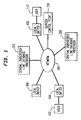
- Figure 1 shows a telephone network system architecture that includes centralized subscriber line database processors 200 and 201.
- the centralized subscriber line database processors 200 and 201 are connected to the telephone network 100 and may include standard off-the-shelf equipment that is very inexpensive when compared to the local switch equipment.
- the telephone network system 100 may connect users 102 and 112 through local switches 104 and 108, respectively.
- a portion of the subscriber information that was conventionally stored exclusively in the local switches 104, 106 and 108 may be stored in the centralized subscriber line database processors 200 and 201.
- the local switches 104 and 108 may be required to request the subscriber information data from the subscriber line database processor 200 before the call can be processed.
- the apparent inefficiency in the additional processing required by each of the local switches 104, 106 and 108 is offset by larger system benefits. For example, centralizing a bulk of the subscriber information in the centralized subscriber line database processors 200 and 201 reduces the complexity and size of the local switches 104, 106 and 108. Because the local switches 104, 106 and 108 no longer have management tasks for a large subscriber information database, the local switches 104, 106 and 108 may be simplified to perform only basic switching actions. Thus, the cost of the already expensive local switches, 104, 106 and 108 is reduced. This advantage is gained without increasing call processing delay time perceived by users 102 and 112.
- a service control point 110 in an intelligent network configuration controls the execution of specialized services such as virtual private networks, free phone (800 numbers), card calling and voice dialing services.
- the service control point 110 must determine which of the local switches 104, 106 and 108 contains the needed subscriber information and then expend local switch resources to extract the subscriber information.
- this process of locating and extracting the subscriber information incur additional time delay.
- the service control point 110 needs only to request the needed subscriber information from the respective centralized subscriber line database processors 200 and 201 without expending any resources of the local switches 104, 106 and 108. Further, the response time of the service control point 110 would be improved because the time delay for searching and locating the subscriber information would be significantly reduced since the subscriber information is stored in the centralized subscriber line database processors 200 and 201.
- the centralized subscriber line database processor 200 and 201 when most of the subscriber information are stored in the centralized subscriber line database processor 200 and 201, complex software required to maintain and manage the subscriber information would be required only at the centralized subscriber line database processors 200 and 201.
- the software that manages the subscriber information at the local switches 104, 106 and 108 can be limited to simple and inexpensive software.
- the centralized subscriber line database processor 200 and 201 adds, deletes and otherwise modifies the subscriber information.
- the centralized subscriber line database processor 200 and 201 may have sophisticated software to provide valuable information such as trend data and other statistical information that can be used for optimizing the telephone network so that better and less expensive services may be offered to subscribers.
- This software may be expensive and the expense is greatly reduced by reducing the number of copies of software required. Thus, the cost of software is drastically reduced by the centralized subscriber line database processors 200 and 201.
- a bulk of the subscriber information is located in each centralized processor complex, greater flexibility is obtained in processing the subscriber information.
- more tailored services can be provided to the subscribers based on the ability to access needed subscriber information from the centralized subscriber line database processors 200 and 201.
- the capability to easily access the subscriber information allows the centralized subscriber line database processors 200 and 201 to determine whether a line is a business or a residential line. This capability permits the offering of services tailored to the business or residential subscribers for both local and long-distance calls.
- the centralized subscriber line database processors 200 and 201 may be distributed throughout the United States or Europe for example. Each of the centralized subscriber line database processors 200 and 201 may be assigned to maintain subscriber information of a large geographic region. Thus, the number of centralized subscriber line database processors 200 and 201 would be much smaller than the number of local switches 104, 106 and 108. For example, the number of centralized subscriber line database processors 200 and 201 could be less than about 10% of the number of local switches 104, 106 and 108. The number of centralized subscriber line database processors 200 and 201 would depend on specific technical requirements of a particular geographical region.
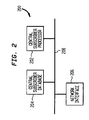
- FIG. 2 shows a block diagram of a subscriber line database processor 200.
- the subscriber line database processor 200 includes a subscriber processor 202, a subscriber database 204, and a network interface 206. All of the above components of the subscriber line database processor 200 are interconnected by signal line 208.
- the subscriber processor 202 receives requests for the subscriber information from the local switches 104, 106 and 108 through the network interface 206. When a request for the subscriber information is received, the subscriber processor 202 fetches the requested information from the subscriber database 204 and transmits the information to the requesting local switches 104, 106 and 108.
- FIG 3 shows a flowchart of a telephone network system processing a call from a user, such as user 102.
- the process begins in step S1000 by the user 102 dialing a telephone number of the user 112. After the telephone network receives the user 102's call, the process goes to step S1002.
- step S1002 the local switch 104 that services the user 102 receives the call. Then, the process goes to step S1004.
- step S1004 the local switch 104 determines whether data from the subscriber database 204 is required for the user 102. If data from the subscriber database 204 is required, the process goes to step S1006; otherwise the process goes to step S1010.
- step S1006 the local switch 104 requests user 102's subscriber information from the subscriber line database processor 200 and the process goes to step S1008.
- step S1008 the subscriber line database processor 200 receives the request from the local switch 104 and fetches the requested subscriber information from the subscriber database 204 and then ends the requested subscriber information to the local switch 104 through the network interface 206. Then the process goes to step S1010.
- step S1010 the local switch 104 processes the call from the user 102 and connects the user 102 with the receiving local switch 108. Then, the process goes to step S1012.
- step S1012 the local switch 108 determines whether subscriber information is required for the user 112. If subscriber information is required, then the process goes to step S1014; otherwise the process goes to step S1018.
- step S1014 the local switch 108 requests user 112's needed subscriber information from the subscriber line database processor 200, and the process goes to step S1016.
- step S1016 the subscriber processor 202 receives the request from the local switch 108, fetches the requested subscriber information from the subscriber database 204, and sends the subscriber information to the local switch 108 through the network interface 206. Then, the process goes to step S1018.
- step S1018 the local switch 108 connects the user 102 with the user 112. And the process ends by going to step S1020.
Abstract
Description


Claims (10)
- A telephone network system, comprising:a telephone network; andcentralized subscriber line database processors coupled to the telephone network, wherein subscriber information is stored in the centralized subscriber line database processors.
- The telephone network system of claim 1, wherein each of the centralized subscriber line database processors comprises:a network interface;a subscriber database; anda subscriber processor coupled to the network interface and the subscriber database, wherein the subscriber processor receives requests from at least one local switch for the subscriber information and responds by retrieving the subscriber information from the subscriber database and sending the requested subscriber information to the at least one local switch through the network interface.
- The telephone network system of claim 2, wherein the subscriber processor manages the subscriber information.
- The telephone network system of claim 3, wherein the subscriber processor adds, deletes and modifies the subscriber information in the subscriber database based on inputs from subscribers.
- The telephone network system of claim 2, wherein the subscriber processor processes the subscriber information to provide tailored services for subscribers based on the subscriber information in the subscriber database.
- The telephone network system of claim 2, wherein the subscriber line database processors consist of standard-off-the-shelf equipment.
- A method for centralizing subscriber information in a telephone network, comprising:storing the subscriber information in a subscriber database of each of centralized subscriber line database processors;receiving requests for the subscriber information from at least one local switch through a network interface;retrieving the subscriber information from the subscriber database with a subscriber processor in response to the requests; andsending the retrieved subscriber information through the network interface to the at least one local switch.
- The method of claim 7, further comprising:managing the subscriber information using the subscriber processor.
- The method of claim 8, wherein the step of managing comprises at least one of adding, deleting and modifying the subscriber information in the subscriber database based on inputs from subscribers.
- The method of claim 7, further comprising:providing tailored services for subscribers based on the subscriber information in the subscriber database.
Applications Claiming Priority (2)
| Application Number | Priority Date | Filing Date | Title |
|---|---|---|---|
| US67861596A | 1996-07-10 | 1996-07-10 | |
| US678615 | 1996-07-10 |
Publications (2)
| Publication Number | Publication Date |
|---|---|
| EP0818935A2 true EP0818935A2 (en) | 1998-01-14 |
| EP0818935A3 EP0818935A3 (en) | 1999-02-24 |
Family
ID=24723543
Family Applications (1)
| Application Number | Title | Priority Date | Filing Date |
|---|---|---|---|
| EP97110870A Withdrawn EP0818935A3 (en) | 1996-07-10 | 1997-07-01 | Centralized subscriber line database and processor |
Country Status (3)
| Country | Link |
|---|---|
| EP (1) | EP0818935A3 (en) |
| JP (1) | JPH1093702A (en) |
| CA (1) | CA2207377A1 (en) |
Cited By (2)
| Publication number | Priority date | Publication date | Assignee | Title |
|---|---|---|---|---|
| CN101697611B (en) * | 2009-11-03 | 2012-07-18 | 中国电信股份有限公司 | Method and system for realizing centralized service deployment in soft exchange |
| CN103338460A (en) * | 2013-06-17 | 2013-10-02 | 北京邮电大学 | Method for calculating centrality of nodes of dynamic network environment |
Citations (3)
| Publication number | Priority date | Publication date | Assignee | Title |
|---|---|---|---|---|
| WO1987005764A1 (en) * | 1986-03-17 | 1987-09-24 | American Telephone & Telegraph Company | Telephone dial-up vendor service |
| WO1993017515A1 (en) * | 1992-02-28 | 1993-09-02 | Bell Atlantic Network Services, Inc. | Area wide centrex |
| US5509060A (en) * | 1993-11-19 | 1996-04-16 | At&T Corp. | Network-accessible intelligent telephone service |
-
1997
- 1997-06-09 CA CA 2207377 patent/CA2207377A1/en not_active Abandoned
- 1997-07-01 EP EP97110870A patent/EP0818935A3/en not_active Withdrawn
- 1997-07-10 JP JP18424997A patent/JPH1093702A/en active Pending
Patent Citations (3)
| Publication number | Priority date | Publication date | Assignee | Title |
|---|---|---|---|---|
| WO1987005764A1 (en) * | 1986-03-17 | 1987-09-24 | American Telephone & Telegraph Company | Telephone dial-up vendor service |
| WO1993017515A1 (en) * | 1992-02-28 | 1993-09-02 | Bell Atlantic Network Services, Inc. | Area wide centrex |
| US5509060A (en) * | 1993-11-19 | 1996-04-16 | At&T Corp. | Network-accessible intelligent telephone service |
Cited By (3)
| Publication number | Priority date | Publication date | Assignee | Title |
|---|---|---|---|---|
| CN101697611B (en) * | 2009-11-03 | 2012-07-18 | 中国电信股份有限公司 | Method and system for realizing centralized service deployment in soft exchange |
| CN103338460A (en) * | 2013-06-17 | 2013-10-02 | 北京邮电大学 | Method for calculating centrality of nodes of dynamic network environment |
| CN103338460B (en) * | 2013-06-17 | 2016-03-30 | 北京邮电大学 | For the computational methods of the node center degree of dynamic network environment |
Also Published As
| Publication number | Publication date |
|---|---|
| EP0818935A3 (en) | 1999-02-24 |
| CA2207377A1 (en) | 1998-01-10 |
| JPH1093702A (en) | 1998-04-10 |
Similar Documents
| Publication | Publication Date | Title |
|---|---|---|
| US5732214A (en) | System for universal archival service where transfer is initiated by user or service and storing information at multiple locations for user selected degree of confidence | |
| CN1105361C (en) | Full distribution information storaging apparatus in distributive exchanging system | |
| EP0410657B1 (en) | Apparatus and method for processing a freephone number telephone call | |
| US5181239A (en) | Call tagging user information in a telephonic environment | |
| JPH07101906B2 (en) | Audio data signal processing method and system | |
| US7212543B1 (en) | Method, system and device for establishing communication between different communication networks | |
| JP3676423B2 (en) | Information communication system | |
| CA2216762C (en) | Methods for automatic service provisioning for telecommunications | |
| CN1166228C (en) | Method and apparatus for providing calling service features within incopletely upgraded cellular telefone networks | |
| AU729923B2 (en) | Method of providing a telecommunication service | |
| US6647431B1 (en) | Method and apparatus for handling I/O messages | |
| EP0818935A2 (en) | Centralized subscriber line database and processor | |
| EP0470415B1 (en) | Call tagging user information in a telephonic environment | |
| JPH08256367A (en) | Personal information management system in personal communication system | |
| EP0913062B1 (en) | User interaction procedure in an intelligent network and corresponding service control point | |
| CN100428762C (en) | Communications | |
| JPS60117991A (en) | Decentralized control exchange system | |
| JP2820942B2 (en) | Communication protocol processing method | |
| WO2000022789A2 (en) | Method, system and device for establishing communication between different communication networks | |
| KR19980061809A (en) | Apparatus for handling currency charges at electronic exchanges | |
| US6567516B1 (en) | Method and device for controlling affiliation of remote line-collection device with switch | |
| KR950005077A (en) | Voice Information Service Call Processing Method of Electronic Switching System | |
| JPH07226977A (en) | Mobile communication service control method | |
| JPH07170379A (en) | Image response system | |
| JPH07222219A (en) | Device and method for private intelligent network |
Legal Events
| Date | Code | Title | Description |
|---|---|---|---|
| PUAI | Public reference made under article 153(3) epc to a published international application that has entered the european phase |
Free format text: ORIGINAL CODE: 0009012 |
|
| AK | Designated contracting states |
Kind code of ref document: A2 Designated state(s): DE FR GB |
|
| AX | Request for extension of the european patent |
Free format text: AL;LT;LV;RO;SI |
|
| PUAL | Search report despatched |
Free format text: ORIGINAL CODE: 0009013 |
|
| AK | Designated contracting states |
Kind code of ref document: A3 Designated state(s): AT BE CH DE DK ES FI FR GB GR IE IT LI LU MC NL PT SE |
|
| AX | Request for extension of the european patent |
Free format text: AL;LT;LV;RO;SI |
|
| AKX | Designation fees paid |
Free format text: DE FR GB |
|
| STAA | Information on the status of an ep patent application or granted ep patent |
Free format text: STATUS: THE APPLICATION IS DEEMED TO BE WITHDRAWN |
|
| 18D | Application deemed to be withdrawn |
Effective date: 19990825 |