BACKGROUND OF THE INVENTION
The present invention relates to a composite
electrode composed of a plurality of organic compounds or
a combination of an organic compound and an inorganic
compound, which is applied for various electrochemical
devices such as batteries, electrochromic display devices,
sensors, memories and the like, and a method for producing
such composite electrodes.
Since the discovery of conductive polyacetylene
by Shirakawa in 1971, vigorous studies have been made on
conductive polymer electrodes, because lightweight
batteries having a higher energy density, electrochromic
display devices having a large area, or electrochemical
devices such as biochemical sensors using a microelectrode
may be realized by the use of such conductive polymers as
electrode materials. Moreover, U.S. Patent No. 4,833,048
proposes an organic disulfide compound as an organic
material from which high energy density can be expected.
A composite polymer electrode of a combination of a
conductive polymer and an organic disulfide compound was
already proposed by the present inventor et al. in J.
Electrochim. Acta, an electrochemical journal published in
England (Vol. 37: 1852, 1992). The composite polymer
electrode is characterized by high voltage, which is a
characteristic feature of conventional conductive polymer
electrodes, and high energy density, which is a
characteristic feature of organic disulfide compounds.
A combination of the composite polymer electrode
and a lithium negative electrode is expected to yield a
potent lithium secondary battery having a voltage of 3 V
or more and an energy density of 150 Wh/kg or more,
equivalent to or overwhelming those of conventional
secondary batteries.
However, conventional composite polymer
electrodes have a drawback such that repeated oxidation-reduction
(charging and discharging) causes gradual
decreases in the capacity of the electrode. An
electrically insulating polydisulfide compound with poor
ionic conductivity, which is a product of polymerization
of an organic disulfide compound by oxidation (charging)
is poor in solubility in an electrolyte. On the other
hand, an organic disulfide monomer, which is a product of
monomerization of a polydisulfide compound by reduction
(discharging) is high in solubility in an electrolyte.
Therefore, repeated oxidation-reduction causes dissolution
of a part of such disulfide monomer into an electrolyte,
and the dissolved monomer is polymerized again at a site
different from the position of the conductive polymer
which is present in the electrode originally. The
electrically insulating polydisulfide compound, which is
deposited as a result of polymerization of the dissolved
monomer apart from the site of the conductive polymer, is
isolated from the electron/ion conductive network inside
the polymer electrode, and plays no role in electrode
reaction. This is the reason why repeated oxidation-reduction
results in gradual decreases of the electrode
capacity.
BRIEF SUMMARY OF THE INVENTION
The object of the present invention is to
provide a composite polymer electrode which will solve the
above-mentioned problem and in which the decrease in
capacity by repeated oxidation-reduction is minimized,
without losing the characteristic features of high voltage
and high energy density, which are the characteristics
inherent to the composite polymer electrode of a
combination of a conductive polymer and an organic
disulfide compound.
Another object of the present invention is to
provide a method for producing such composite polymer
electrodes.
The present invention is directed to a composite
electrode comprising an organic disulfide compound which
contains at least one sulfur-sulfur bond, wherein the
sulfur-sulfur bond is cleaved when electrically reduced to
form a sulfur-metal ion bond and the sulfur-metal ion bond
is regenerated into the sulfur-sulfur bond when
electrically oxidized, the metal ion including proton
(hereinafter referred to as "organic disulfide compound"),
polyaniline, and polyvinylidene fluoride.
The present invention also provides a composite
electrode comprising an organic disulfide compound,
polyaniline, a metal oxide, and polyvinylidene fluoride.
Addition of the polyvinylidene fluoride
effectively reduces dissolution and escape of the organic
disulfide compound, polyaniline, or a complex of these two
into the electrolyte during oxidation-reduction (charging
and discharging) of the composite polymer electrode,
thereby imparting excellent characteristics against
repeated oxidation-reduction (charging-discharging) to the
electrode.
The present invention can give a composite
electrode characterized by excellent performance against
repeated oxidation-reduction (charging-discharging).
Application of the composite electrode as the positive
electrode of a lithium secondary battery realizes a
battery having a long charge-discharge cycle life.
Other than batteries, employment of the
composite electrode of the present invention for the
counter electrode also realizes an electrochromic display
device having a long coloring and decoloring life and an
electrochemical analogue memory having a long life against
repeated read and write operations.
While the novel features of the invention are
set forth particularly in the appended claims, the
invention, both as to organization and content, will be
better understood and appreciated, along with other
objects and features thereof, from the following detailed
description taken in conjunction with the drawings.
BRIEF DESCRIPTION OF THE SEVERAL VIEWS OF THE DRAWING
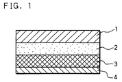
FIG. 1 is a rough longitudinal cross-sectional
view of a lithium secondary battery element for evaluating
composite electrodes of the embodiments in accordance with
the present invention.
DETAILED DESCRIPTION OF THE INVENTION
In a preferred mode of the present invention,
the composite electrode comprises an organic disulfide
compound, polyaniline, and polyvinylidene fluoride.
In another preferred mode of the present
invention, the composite electrode comprises an organic
disulfide compound, polyaniline, polyvinylidene fluoride,
and a metal oxide.
The presence of polyvinylidene fluoride imparts
adequate flexibility to the composite electrode, thereby
realizing a thin film secondary battery or other thin film
electrochemical devices. The polyvinylidene fluoride also
functions to minimize dissolution and migration of the
organic disulfide compound, polyaniline, or a complex of
these two into the electrolyte during oxidation-reduction
(charging and discharging), thereby imparting excellent
characteristics against repeated oxidation-reduction
(charging-discharging) to the electrode. Furthermore,
the presence of this substance helps to alleviate
relaxation of the composite electrode due to a change in
volume caused by oxidation-reduction reaction of the
metal oxide and minimizes deterioration of the
characteristics of the electrode induced by repeated
oxidation-reduction reaction markedly.
Particularly, polyvinylidene fluoride, which is
a copolymer of a kind of polyvinylidene fluoride,
vinylidene difluoride and propylene hexafluoride can
absorb a large amount of an organic electrolyte which
comprises a lithium salt, such as LiBF4, LiClO4, LiPF6,
or the like, and a non-protonic organic solvent therefor,
such as ethylene carbonate, propylene carbonate, diethyl
carbonate, dimethyl carbonate, or the like. The
polyvinylidene fluoride is advantageous in that if a
composite electrode containing the polyvinylidene fluoride
is applied to an electrochemical device such as battery,
an organic electrolyte included in the electrolyte layer
is absorbed by this substance, which helps the development
of an ion conduction pathway inside the composite
electrode, thereby enabling oxidation-reduction reaction
at a large current.
Furthermore, the method for producing composite
electrodes in accordance with the present invention uses
N-R-2-pyrrolidone where R represents hydrogen atom or an
alkyl group, such as CH3, C2H5, n-C4-H9, and the like,
which serves as a good solvent for all of the polyaniline,
organic disulfide compound and polyvinylidene fluoride, so
that these components can be mixed homogeneously at
molecular level. Therefore, the method for producing
composite electrodes in accordance with the present
invention is effective for obtaining a thin film or a
large area composite electrode of homogeneous composition
with ease. A commercially available reagent can be used
as the N-R-2-pyrrolidone.
The method for producing composite electrodes in
accordance with the present invention comprises the steps
of dissolving an organic disulfide compound and
polyvinylidene fluoride in N-R-2-pyrrolidone to prepare a
viscous solution, adding and dissolving a polyaniline
powder to and in the viscous solution thus prepared to
prepare a solution "A", and applying the resultant
solution "A" onto a conductive substrate of, for example,
a silver plated copper foil, followed by heating it in a
vacuum or in an inert gas atmosphere to remove the
existing N-R-2-pyrrolidone partially or entirely. Since
the polyaniline is not easily dissolved in a solvent
lacking an organic disulfide compound, it is preferable to
dissolve the organic disulfide compound in the N-R-2-pyrrolidone
beforehand prior to addition of the
polyaniline in the above-mentioned steps.
In another preferred mode of the method for
producing composite electrodes in accordance with the
present invention, the polyaniline is molded into a film
beforehand, to which a viscous N-R-2-pyrrolidone solution
dissolving the organic disulfide compound and the
polyvinylidene fluoride is applied, and then the resultant
is heated at 60 to 100°C in a vacuum or in an inert gas
atmosphere, thereby to produce a composite film of which
one surface is rich in polyaniline and other surface is
rich in organic disulfide compound. The polyaniline film
can be produced by depositing polyaniline on a substrate
by electrolytic polymerization. Another method for
producing a polyaniline film comprises the steps of
dissolving polyaniline synthesized by electrolytic
polymerization or chemical polymerization in N-R-2-pyrrolidone
and applying the resultant solution onto a
substrate, followed by heating it in a vacuum or in an
inert gas atmosphere to remove the existing N-R-2-pyrrolidone
partially or entirely.
In still another preferred mode of the method
for producing composite electrodes in accordance with the
present invention, a viscous solution "B" is obtained by
the steps of 1) dissolving an organic disulfide compound
in N-R-2-pyrrolidone, and 2) dissolving a polyaniline
powder in the resultant solution, which is further heated
to dissolve, or diluted with N-R-2-pyrrolidone, if
necessary. This is because, as discussed above,
polyaniline is not easy to dissolve in a solvent lacking
an organic disulfide compound. Because it is difficult to
dissolve polyvinylidene fluoride or mix a metal oxide
directly in or directly with the viscous solution "B", a
dispersed mixture "C" is prepared primarily, in which a
metal oxide powder is dispersed in N-R-2-pyrrolidone
dissolving polyvinylidene fluoride. Then, the viscous
solution "B" is mixed with the dispersed mixture "C"
homogeneously using a homogenizer, thereby to obtain a
dispersed mixture "D". The resultant dispersed mixture
"D" is applied onto a conductive substrate of, for
example, a silver plated copper foil, which is then heated
in a vacuum or in an inert gas atmosphere to remove the
existing N-R-2-pyrrolidone partially or entirely.
In the present invention, a homopolymer prepared
by polymerizing vinylidene difluoride alone and a
copolymer of vinylidene difluoride and a vinyl fluoride
monomer such as ethylene tetrafluoride or propylene
hexafluoride can be used as the polyvinylidene fluoride.
Polyvinylidene fluorides having a mean molecular weight of
100,000 to 500,000 are preferable. The polyvinylidene
fluoride is exemplified as "KUREMA KF polymer",
manufactured by Kureha Chemical Industry Co., Ltd. "KF
#1100" and "KF2300", manufactured by Kureha Chemical
Industry Co., Ltd., can be used as the homopolymer and the
copolymer of vinylidene difluoride and propylene
hexafluoride, respectively.
As the organic disulfide compound, the compound
described in U.S. Patent No. 4,833,048, represented by the
general formula R(S)y)n where R represents an aliphatic
group or an aromatic group, and S represents sulfur, and
where y is an integer of 1 or larger and n is an integer
of 2 or larger, can be used. Commercially available
dithioglycol represented by HSCH2CH2SH, 2,5-dimercapto-1,3,4-thiadiazole
represented by C2N2S(SH)2, s-triazine-2,4-6-trithiol
represented by C3H3N3S3, 7-methyl-2,6,8-trimercaptopurine
represented by C6H6N4S3, and 4,5-diamino-2,6-dimercaptopyrimidine
represented by C4H6N4S2
can also be used without applying any treatment.
As the polyaniline, polymerized aniline by
electrolytic or chemical oxidation is used. Reduced
polyaniline in dedoped state is preferable from the point
of solubility. An example of such polyaniline is
"ANILEAD", manufactured by Nitto Denko Corporation. The
reduction degree index (RDI) of polyaniline is expressed
by electron absorption spectrum of a solution containing a
small amount of polyaniline dissolved in N-methyl-2-pyrrolidone.
This means that RDI = I640/I340 , which
represents the ratio of the peak intensity I640 expressed
at a long wavelength around 640 nm, derived from the
quinonediimine structure, to the peak intensity I340
expressed at a short wavelength around 340 nm, derived
from the para substituted benzene structure. Polyaniline
having an RDI of 0.5 or less is used preferably. The
degree of dedoping of polyaniline is represented by the
level of conductivity. Polyaniline having a conductivity
of 10-5 S/cm or less is used preferably.
As the metal oxide, although any transition
metal oxide or any composite oxide may be used, a compound
having an electrochemical equivalent exceeding or
equivalent to the electrochemical equivalent of
polyaniline, that is, 150 mAh/g, is particularly
preferred. Preferable transition metal oxides may be
exemplified as LiCoO2 (electrochemical equivalent: 140 to
160 mAh/g), V6O13 (160 to 230 mAh/g), LiMn2O4 (100 to 120
mAh/g), V2O5 (130 to 150 mAh/g), and LiNiO2 (140 to 220
mAh/g). A metal oxide powder having a mean particle
diameter around 1 to 10 µm may also be used. Any
transition metal oxide containing plural transition metal
elements may also be used without problem. For example,
any composite oxide derived from LiCoO2 in which a part of
Co is substituted with Mn, Ni or Fe, or any composite
oxide derived from V6O13 in which a part of V is
substituted with W (tungsten) may also be used.
It is preferable that the amount of
polyvinylidene fluoride is 0.1 to 10% by weight of the
total amount of the organic disulfide compound, N-R-2-pyrrolidone
and polyaniline, or the total amount of the
organic disulfide compound, N-R-2-pyrrolidone, polyaniline
and metal oxide. With respect to the proportion of the
organic disulfide compound, N-R-2-pyrrolidone and
polyaniline, it is preferable to contain the N-R-2-pyrrolidone
and polyaniline in a range of 0.5 to 5 moles
and 0.05 to 5 moles, respectively, per 1 mole of the
organic disulfide compound. The metal oxide is contained
preferably in a range of 0.5 to 5 parts by weight per 1
part of the polyaniline.
Protons may also be used as the metal ions for
producing a salt by reduction of the organic disulfide
compound, other than the alkali metal ions and alkaline
earth metal ions as disclosed in the U.S. patent cited
before. Particularly, in the case of alkali metal ions,
it is possible to obtain a lithium secondary battery
having a high energy density exceeding 200 Wh/kg at a
voltage of about 3 V by using metal lithium or a lithium
alloy such as lithium-aluminum alloy as an electrode which
supplies and captures lithium ions and a lithium ion-conductive
electrolyte in combination. Furthermore, if a
hydride of a hydrogen storage alloy such as LaNi5 is
adopted as an electrode which supplies and captures
protons, a battery having a voltage of 1 to 2 V can be
obtained by using a proton-conductive electrolyte in
combination.
The composite electrode of the present invention
may further contain, if necessary, a conductive agent such
as carbon, a shape forming agent or a reinforcement agent
such as synthetic rubber, resin, ceramic powder, etc., in
addition to the above-mentioned components.
A combination of the positive electrode using
the composite electrode of the present invention, a
nonaqueous electrolyte containing lithium ions, and a
negative electrode which absorbs and desorbs lithium ions
reversibly during charge and discharge can give a high
energy density lithium secondary battery having
exceptional cycle life characteristics against repeated
charge and discharge operations. More specifically, as
the negative electrode, metal lithium, lithium alloys such
as lithium-aluminum, lithium-manganese, etc., materials
capable of reversibly intercalating and deintercalating
lithium ions such as carbon materials, metal sulfides, or
conductive polymer materials may be used. The use of a
copolymer of vinylidene difluoride and propylene
hexafluoride as the polyvinylidene fluoride can realize a
lithium secondary battery chargeable and dischargeable at
a large current.
In the following, the present invention will be
described more specifically by way of embodiments.
Example 1
A vinylidene difluoride-propylene hexafluoride
copolymer (a KF polymer KF #2300, manufactured by Kureha
Chemical Industry Co., Ltd.; melting point 151°C) was
dissolved in N-methyl-2-pyrrolidone (hereinafter
abbreviated to "NMP") at a concentration of 2% by weight.
In 6 g of the resultant solution, 1.5 g (0.01 mole) of a
monomer powder of 2,5-dimercapto-1,3,4-thiadiazole
(hereinafter abbreviated to "DMcT") was dissolved as an
organic disulfide compound, and a viscous transparent
yellow NMP-KF polymer-DMcT solution was obtained.
Then, 1.0 g (0.0067 mole) of a powder of
"ANILEAD" manufactured by Nitto Denko Corporation, was
added in the dedoped and reduced state as the polyaniline
to the NMP-KF polymer-DMcT solution, which gave another
viscous dark green solution.
The resultant viscous solution was applied onto
a silver plated copper foil (the thickness of the silver
plated layer: 1 µm and the entire thickness of the foil:
17 µm) in a thickness of 90 µm, which was then heat
treated under a reduced pressure of 1 mmHg at 80°C. This
treatment caused an escape of 82% by weight of NMP. The
content of the KF polymer in the resultant film was 3.3%
by weight of the total amount of DMcT, polyaniline and
NMP. The 15-µm-thick composite film thus obtained was cut
into 2 × 2 cm sheets together with the copper foil, which
gave a composite electrode "A". The composite electrode
film of the composite electrode "A" weighed 9.0 mg.
Example 2
In a similar manner, another composite electrode
"B" was obtained, with the exception of the use of a
vinylidene difluoride homopolymer (a polymer KF #1100,
manufactured by Kureha Chemical Industry Co., Ltd.;
melting point 177°C) in place of KF #2300 used in Example
1. The composite electrode film of the composite
electrode "B" had a thickness of 15 µm and weighed 8.9 mg.
Comparative Example 1
A viscous transparent yellow NMP-DMcT solution
was obtained by dissolving 1.5 g (0.01 mole) of a DMcT
monomer powder in 5 g of NMP.
The resultant solution was added with 1.0 g of
polyaniline used in Example 1, and heated at 80°C in a
sealed vessel of which air has been substituted with an
inert gas, which gave a viscous greenish black solution.
The viscous solution thus prepared was applied
onto a silver plated copper foil (the thickness of the
silver plated layer: 1 µm and the entire thickness of the
foil: 17 µm) in a thickness of 90 µm, which was then heat
treated under a reduced pressure of 1 mmHg at 80°C. This
treatment caused an escape of 68% by weight of NMP. The
15-µm-thick composite film thus obtained was cut into 2 ×
2 cm sheets together with the copper foil, which gave a
composite electrode "C". The composite electrode film of
the composite electrode "C" weighed 8.6 mg.
Example 3
Another viscous transparent yellow NMP-DMcT
solution was obtained by dissolving 1.5 g (0.01 mole) of a
DMcT monomer powder in 5 g of NMP.
The resultant solution was added with 2.0 g
(0.013 mole) of polyaniline used in Example 1, and heated
at 80°C in a sealed vessel of which air has been
substituted with an inert gas, which gave a viscous purple
black solution.
Then, a powder of V6O13 having a mean particle
diameter of 3 µm, which was prepared by hydrolysis of
vanadium buthoxide followed by heating, was mixed with and
dispersed in 10 g of an NMP solution dissolving KF #2300
used in Example 1 at a concentration of 2% by weight,
which gave a slurry.
The slurry was added to the previously prepared
viscous purple black solution and homogenized using a
homogenizer at 5,000 rpm for about 10 minutes, and another
viscous dispersed solution was obtained, which was then
applied onto a 5-µm thick titanium foil in a thickness of
200 µm and heated at 80°C for about 120 minutes under a
reduced pressure of 1 mmHg. In this way, a composite
electrode film having a thickness of 25 µm was obtained.
Heating under reduced pressure resulted in an escape of
86% by weight of NMP. The content of the KF polymer in
the film thus obtained was 2.4% by weight of the total
amount of DMcT, polyaniline, V6O13 and NMP. The
composite film was cut into 2 × 2 cm sheets together with
the titanium foil, which gave a composite electrode "D".
The composite electrode film of the composite electrode
"D" weighed 25 mg.
Example 4
Similarly, another composite electrode "E" was
obtained, with the exception of the use of KF #1100 in
Example 2 in place of KF #2300 in Example 3. The
composite electrode film of the composite electrode "E"
had a thickness of 25 µm and weighed 25 mg.
Comparative Example 2
A viscous transparent yellow NMP-DMcT solution
was obtained by dissolving 1.5 g (0.01 mole) of a DMcT
monomer powder in 5 g of NMP.
The resultant solution was added with 2.0 g of
polyaniline used in Example 1, and heated at 80°C in a
sealed vessel of which air has been substituted with an
inert gas, which gave a viscous purple black solution.
Then, a slurry was prepared by dispersing 2.5 g
of V6O13 powder similar to Example 3 in 10 g of NMP.
The slurry was added to the previously prepared
viscous purple black solution and homogenized using a
homogenizer at 5,000 rpm for about 10 minutes. In this
way, a viscous dispersed solution was obtained, which was
then applied onto a 5 µm-thick titanium foil in a
thickness of 250 µm and heated under a reduced pressure of
1 mmHg at 80°C for about 120 minutes, which gave a
composite electrode film having a thickness of 22 µm.
Heating under reduced pressure caused an escape of 72% by
weight of NMP. The composite electrode film thus obtained
was cut into 2 × 2 cm sheets together with the titanium
foil, which gave a composite electrode "F". The composite
electrode film of the composite electrode "F" weighed 19
mg.
Example 5
Similarly, another composite electrode "G" was
obtained using an LiCoO2 powder having a mean particle
diameter of 2 µm, which was prepared by heat treating a
mixture of lithium carbonate and cobalt oxide (Co2O3), in
place of the V6O13 powder in Example 3. The composite
electrode film of the composite electrode "G" had a
thickness of 26 µm and weighed 24 mg.
Example 6
In a similar manner, another composite electrode
"H" was obtained, using an LiCoO2 powder having a mean
particle diameter of 2 µm, which was prepared by heat
treating a mixture of lithium carbonate and cobalt oxide
(Co2O3), in place of the V6O13 powder in Example 4. The
composite electrode film of the composite electrode "H"
had a thickness of 26 µm and weighed 24 mg.
Comparative Example 3
A composite electrode "I" was obtained in the
same manner as in Comparative Example 2, with the
exception of the use of an LiCoO2 powder having a mean
particle diameter of 2 µm, which was prepared by heat
treating a mixture of lithium carbonate and cobalt oxide
(Co2O3), in place of the V6O13 powder in Comparative
Example 2. The composite electrode film of the composite
electrode "I" had a thickness of 24 µm and weighed 22 mg.
Example 7
Similarly, a composite electrode "J" was
obtained, using an LiNiO2 powder having a mean particle
diameter of 3 µm, which was prepared by heat treating a
mixture of lithium hydroxide and nickel hydroxide, in
place of the V6O13 powder in Example 3. The composite
electrode film of the composite electrode "J" had a
thickness of 26 µm and weighed 24 mg.
Example 8
Another composite electrode "K" was obtained,
using an LINiO2 powder having a mean particle diameter of
3 µm, which was prepared by heat treating a mixture of
lithium hydroxide and nickel hydroxide, in place of the
V6O13 powder in Example 4. The composite electrode film
of the composite electrode "K" had a thickness of 26 µm
and weighed 24 mg.
Comparative Example 4
A composite electrode "L" was obtained in the
same manner as in Comparative Example 2, with the
exception of the use of an LiNiO2 powder having a mean
particle diameter of 3 µm, which was prepared by heat
treating a mixture of lithium hydroxide and nickel
hydroxide, in place of the V6O13 powder in Comparative
Example 2. The composite electrode film of the composite
electrode "L" had a thickness of 24 µm and weighed 22 mg.
Example 9
In the same manner as in Example 3, a composite
electrode "M" was obtained, with the exception of the use
of an LiMn2O4 powder having a mean particle diameter of 1
µm, which was prepared by heat treating a mixture of
lithium carbonate and manganese oxide (Mn3O4), in place
of the V6O13 powder in Example 3. The composite
electrode film of the composite electrode "M" had a
thickness of 23 µm and weighed 21 mg.
Example 10
Similarly, another composite electrode "N" was
obtained, using an LiMn2O4 powder having a mean particle
diameter of 1 µm, which was prepared by heat treating a
mixture of lithium carbonate and manganese oxide (Mn3O4),
in place of the V6O13 powder in Example 4. The composite
electrode film of the composite electrode "N" had a
thickness of 23 µm and weighed 21 mg.
Comparative Example 5
A composite electrode "O" was obtained in the
same manner as in Comparative Example 2, with the
exception of the use of an LiMn2O4 powder having a mean
particle diameter of 1 µm, which was prepared by heat
treating a mixture of lithium carbonate and manganese
oxide (Mn3O4), in place of the V6O13 powder in
Comparative Example 2. The composite electrode film of
the composite electrode "O" had a thickness of 22 µm and
weighed 19 mg.
Example 11
A composite electrode "P" was obtained in the
same manner as in Example 3, with the exception of the use
of a V2O5 powder having a mean particle diameter of 7 µm,
in place of the V6O13 powder in Example 3. The composite
electrode film of the composite electrode "P" had a
thickness of 23 µm and weighed 22 mg.
Example 12
Similarly, a composite electrode "Q" was
obtained, with the exception of the use of a V2O5 powder
having a mean particle diameter of 7 µm, in place of the
V6O13 powder in Example 4. The composite electrode film
of the composite electrode "Q" had a thickness of 23 µm
and weighed 22 mg.
Comparative Example 6
A composite electrode "R" was obtained in the
same manner as in Comparative Example 2, with the
exception of the use of a V2O5 powder having a mean
particle diameter of 7 µm, in place of the V6O13 powder
in Comparative Example 2. The composite electrode film of
the composite electrode "R" had a thickness of 22 µm and
weighed 18 mg.
Subsequently, electrode performance was examined
in these composite electrodes.
Batteries "A" to "R" each having a size of 2 × 2
cm were assembled using the corresponding composite
electrode films "A" to "R" obtained in Examples 1 to 12
and Comparative Examples 1 to 6 as positive electrodes,
metal lithium sheets having a thickness of 0.3 mm as
negative electrodes, and gel polymer electrolytes having a
thickness of 0.5 mm as separators. The gel polymer
electrolyte used here is one which was prepared by gelling
4.5 g of a KF copolymer KF #2300 used in Example 1 in a
propylene carbonate-ethylene carbonate mixture in a molar
ratio of 1 : 2 containing 1 M LiBF4 dissolved therein.
FIG. 1 shows the structure of the above-mentioned
battery element. A composite electrode film 2
formed over a conductive substrate 1 of silver plated
copper film or titanium film functions as the positive
electrode, and a negative electrode 4 of metal lithium is
disposed thereon with a gel polymer electrolyte 3
interposed therebetween.
The battery element is sealed by 2 metal sheets
for sandwiching the battery element and a sealing material
for eclectically insulating and sealing the periphery of
the metal sheets.
The batteries "A" to "R" were charged and
discharged at a constant current of 0.2 mA at 20°C in a
voltage range of 4.25 to 2.5 V. The discharge capacity
after each charging and discharging cycle was measured,
and the electrode performance was evaluated based on the
level of reduction in discharge capacity with the progress
of charge and discharge cycles. The results are shown in
Table 1. Test cells showing less reductions in discharge
capacity with the progress of charge and discharge cycles
have better charge discharge cycle life performance.
| Battery | Discharge capacity (mAh) |
| | Charge and discharge cycles |
| | 1 | 10 | 50 | 100 | 150 | 200 |
| A | 1.53 | 1.63 | 1.63 | 1.62 | 1.60 | 1.58 |
| B | 1.50 | 1.62 | 1.62 | 1.60 | 1.55 | 1.45 |
| C | 1.10 | 1.25 | 1.05 | 0.85 | 0.75 | 0.60 |
| D | 3.62 | 4.08 | 4.05 | 3.86 | 3.63 | 3.58 |
| E | 3.40 | 3.96 | 3.78 | 3.55 | 3.27 | 3.20 |
| F | 2.05 | 2.22 | 1.95 | 1.62 | 1.41 | 1.28 |
| G | 3.20 | 3.15 | 3.15 | 3.12 | 3.12 | 3.10 |
| H | 3.18 | 3.14 | 3.14 | 3.12 | 2.98 | 2.86 |
| I | 2.12 | 1.95 | 1.95 | 1.72 | 1.55 | 1.15 |
| J | 3.41 | 3.38 | 3.38 | 3.25 | 3.21 | 3.18 |
| K | 3.36 | 3.28 | 3.26 | 3.26 | 3.18 | 3.14 |
| L | 2.54 | 2.30 | 2.28 | 2.12 | 2.00 | 1.86 |
| M | 2.32 | 2.42 | 2.31 | 2.30 | 2.30 | 2.26 |
| N | 2.28 | 2.22 | 2.23 | 2.18 | 2.16 | 2.12 |
| O | 1.74 | 1.64 | 1.62 | 1.45 | 1.32 | 1.21 |
| P | 2.96 | 2.82 | 2.80 | 2.78 | 2.78 | 2.71 |
| Q | 2.87 | 2.79 | 2.75 | 2.75 | 2.69 | 2.64 |
| R | 1.83 | 1.71 | 1.71 | 1.58 | 1.44 | 1.28 |
As apparent from the results, in the batteries
having the corresponding composite electrodes of the
examples in accordance with the present invention, the
reduction in discharge capacity with the progress of
charge and discharge cycles is less than that of the
batteries having the corresponding composite electrodes of
Comparative Examples. Furthermore, addition of
polyvinylidene fluoride helps to increase the amount of
NMP, which does not play any role in electrode reaction,
escaping from the composite electrode films in fabricating
them. This yields an additional secondary effect such
that the capacity per weight of composite electrode film
can be increased.
The batteries "A" to "R" were further subjected
to 10 cycles of charge and discharge at a constant current
of 0.2 mA at 20°C in a voltage range of 4.25 to 2.5 V,
followed by charging at 0.25 mA until the voltage reaches
4.25 V. The batteries were then stood still for 2 hours
in open circuit state. Subsequently, the batteries were
charged and discharged at ascending current levels from
0.5, 1.0, 2.0, 5.0, to 10.0 mA; charging and discharging
at each current was performed for 20 seconds,
respectively. Upon discharging for 20 seconds at each
current, the discharge voltage was measured. Electrode
performance in each battery was evaluated based on the
degree in reduction in discharge voltage. The results are
shown in Table 2. Test cells showing less reductions in
discharge voltage with the progress of charge and
discharge cycles have larger output current values.
| Battery | Discharge voltage (V) |
| | Current value (mA) |
| | 0.0 | 0.5 | 1.0 | 2.0 | 5.0 | 10.0 |
| A | 4.15 | 4.12 | 4.07 | 3.95 | 3.78 | 3.48 |
| B | 4.15 | 4.10 | 4.02 | 3.87 | 3.62 | 3.12 |
| C | 4.10 | 3.96 | 3.80 | 3.56 | 3.12 | 2.53 |
| D | 4.06 | 4.02 | 3.95 | 3.81 | 3.60 | 3.28 |
| E | 4.05 | 4.00 | 3.90 | 3.70 | 3.42 | 3.10 |
| F | 4.03 | 3.85 | 3.64 | 3.39 | 3.01 | 2.42 |
| G | 4.07 | 4.02 | 3.96 | 3.80 | 3.56 | 3.30 |
| H | 4.06 | 4.00 | 3.89 | 3.61 | 3.22 | 2.94 |
| I | 4.07 | 3.95 | 3.83 | 3.42 | 3.04 | 2.38 |
| J | 4.06 | 4.02 | 3.96 | 3.79 | 3.57 | 3.31 |
| K | 4.06 | 3.98 | 3.89 | 3.60 | 3.20 | 2.95 |
| L | 4.06 | 3.94 | 3.82 | 3.42 | 3.00 | 2.32 |
| M | 4.20 | 4.18 | 4.15 | 4.06 | 3.87 | 3.72 |
| N | 4.20 | 4.16 | 4.12 | 4.01 | 3.82 | 3.64 |
| O | 4.20 | 4.12 | 4.01 | 3.86 | 3.58 | 3.26 |
| P | 4.02 | 3.96 | 3.87 | 3.69 | 3.42 | 3.26 |
| Q | 4.00 | 3.92 | 3.80 | 3.58 | 3.39 | 3.10 |
| R | 4.00 | 3.90 | 3.75 | 3.52 | 3.30 | 3.02 |
As clearly understood from the results, the
batteries having the corresponding composite electrodes of
the examples in accordance with the present invention are
less in reduction in discharge voltage with the increase
in current level and have larger output current values,
compared with those of the batteries having the
corresponding composite electrodes of Comparative
Examples. Particularly, the batteries, in which the
copolymer of vinylidene difluoride and propylene
hexafluoride was used as the polyvinylidene fluoride, can
give much larger output current, compared with the
batteries having the vinylidene difluoride homopolymer.
Although the present invention has been
described in terms of the presently preferred embodiments,
it is to be understood that such disclosure is not to be
interpreted as limiting. Various alterations and
modifications will no doubt become apparent to those
skilled in the art to which the present invention
pertains, after having read the above disclosure.
Accordingly, it is intended that the appended claims be
interpreted as covering all alterations and modifications
as fall within the true spirit and scope of the invention.